

Product Guide
Page 2
...8686 This equipment has been tested and found to specifications and product descriptions at : http://www.intel.com/ or by turning the equipment off and on the board, the following statement applies: FCC Declaration of this device must accept any intellectual property rights is...if not installed and used in accordance with Part 15 of the FCC Rules. Intel products are trademarks or registered trademarks of the Intel® Desktop Boards D845GLLY and D845GLAD Product Guide. The Desktop Boards D845GLLY and D845GLAD may contain design defects or errors known as provided in medical, life...
...8686 This equipment has been tested and found to specifications and product descriptions at : http://www.intel.com/ or by turning the equipment off and on the board, the following statement applies: FCC Declaration of this device must accept any intellectual property rights is...if not installed and used in accordance with Part 15 of the FCC Rules. Intel products are trademarks or registered trademarks of the Intel® Desktop Boards D845GLLY and D845GLAD Product Guide. The Desktop Boards D845GLLY and D845GLAD may contain design defects or errors known as provided in medical, life...

Product Guide
Page 3
Contents 1 Desktop Board Features Desktop Board Components 9 Processor ...10 Main Memory ...11 Intel® 845GL Chipset...11 Intel® 82845GL Graphics and Memory Controller Hub (GMCH 12 Intel® 82801DB I/O Controller Hub (ICH4 12 Firmware Hub (FWH 12 Input/Output (I/O) Controller 12... Support 18 Speaker...18 Battery...18 Real-Time Clock...18 2 Installing and Replacing Desktop Board Components Before You Begin ...19 Installing the I/O Shield...20 Installing and Removing the Desktop Board 21 Installing and Removing a Processor 22 Installing a Processor 22 Installing the Processor ...
Contents 1 Desktop Board Features Desktop Board Components 9 Processor ...10 Main Memory ...11 Intel® 845GL Chipset...11 Intel® 82845GL Graphics and Memory Controller Hub (GMCH 12 Intel® 82801DB I/O Controller Hub (ICH4 12 Firmware Hub (FWH 12 Input/Output (I/O) Controller 12... Support 18 Speaker...18 Battery...18 Real-Time Clock...18 2 Installing and Replacing Desktop Board Components Before You Begin ...19 Installing the I/O Shield...20 Installing and Removing the Desktop Board 21 Installing and Removing a Processor 22 Installing a Processor 22 Installing the Processor ...
Product Guide
Page 4
Intel Desktop Boards D845GLLY and D845GLAD Product Guide Installing and Removing Memory 23 Installing DIMMs ...24 Removing DIMMs ...24 Connecting the IDE Cable 25 Connecting the Front Panel Header ... Panel USB Solution 27 Clearing Passwords...28 Replacing the Battery ...29 3 Updating the BIOS Updating the BIOS with the Intel® Express BIOS Update Utility 33 Updating the BIOS with the Intel® Flash Memory Update Utility 33 Obtaining the BIOS Update File 33 Updating the BIOS...34 Recovering the BIOS 34...
Intel Desktop Boards D845GLLY and D845GLAD Product Guide Installing and Removing Memory 23 Installing DIMMs ...24 Removing DIMMs ...24 Connecting the IDE Cable 25 Connecting the Front Panel Header ... Panel USB Solution 27 Clearing Passwords...28 Replacing the Battery ...29 3 Updating the BIOS Updating the BIOS with the Intel® Express BIOS Update Utility 33 Updating the BIOS with the Intel® Flash Memory Update Utility 33 Obtaining the BIOS Update File 33 Updating the BIOS...34 Recovering the BIOS 34...

Product Guide
Page 5
...Desktop Board D845GLLY 31 12. Add-in Card and Peripheral Interface Connectors 63 16. Connecting the IDE Cable 25 9. Front Panel Headers...64 v Desktop Board Mounting Holes 21 5. Installing a Processor 22 6. Power and Hardware Control Connectors 62 15. Back Panel Connectors 60 13. Contents 5 Technical Reference Board...Audio Connectors 61 Power and Hardware Connectors 62 Add-In Card and Peripheral Interface Connectors 63 Front Panel Headers 64 Desktop Board Resources 66 Memory Map ...66 DMA Channels ...66 Interrupts ...67 A Error Messages and Indicators BIOS Beep Codes ...
...Desktop Board D845GLLY 31 12. Add-in Card and Peripheral Interface Connectors 63 16. Connecting the IDE Cable 25 9. Front Panel Headers...64 v Desktop Board Mounting Holes 21 5. Installing a Processor 22 6. Power and Hardware Control Connectors 62 15. Back Panel Connectors 60 13. Contents 5 Technical Reference Board...Audio Connectors 61 Power and Hardware Connectors 62 Add-In Card and Peripheral Interface Connectors 63 Front Panel Headers 64 Desktop Board Resources 66 Memory Map ...66 DMA Channels ...66 Interrupts ...67 A Error Messages and Indicators BIOS Beep Codes ...

Product Guide
Page 6
...J8A1 61 31. Front Panel USB 2.0 Header (J9F2 65 32. Safety Regulations...73 39. Feature Summary ...7 2. Processors Supported by the Desktop Board 10 3. Jumper Settings for the Front Panel USB Wake Configuration Jumper Block (J9F1)... 27 6. Chipset Configuration Submenu 51 21. Boot Menu... (J9G1 65 33. System Memory Map 66 34. Security Menu...52 22. EMC Regulations ...73 vi Power Menu...53 23. Intel Desktop Boards D845GLLY and D845GLAD Product Guide Tables 1. Primary/Secondary IDE Master/Slave Submenus 46 16. ACPI Submenu ...53 24. Interrupts ...67 36....
...J8A1 61 31. Front Panel USB 2.0 Header (J9F2 65 32. Safety Regulations...73 39. Feature Summary ...7 2. Processors Supported by the Desktop Board 10 3. Jumper Settings for the Front Panel USB Wake Configuration Jumper Block (J9F1)... 27 6. Chipset Configuration Submenu 51 21. Boot Menu... (J9G1 65 33. System Memory Map 66 34. Security Menu...52 22. EMC Regulations ...73 vi Power Menu...53 23. Intel Desktop Boards D845GLLY and D845GLAD Product Guide Tables 1. Primary/Secondary IDE Master/Slave Submenus 46 16. ACPI Submenu ...53 24. Interrupts ...67 36....

Product Guide
Page 7
Feature Summary Form Factors Processor Memory • microATX at : http://support.intel.com/support/motherboards/desktop/ Intel® 845GL chipset, consisting of Intel®Desktop Boards D845GLLY and D845GLAD. 1 Desktop Board Features ✏ NOTE Intel®Desktop Board D845GLAD layout was used for : • 400 MHz front side bus (FSB) Intel® Pentium® 4 processor in an mPGA-478 socket • 400 MHz FSB...
Feature Summary Form Factors Processor Memory • microATX at : http://support.intel.com/support/motherboards/desktop/ Intel® 845GL chipset, consisting of Intel®Desktop Boards D845GLLY and D845GLAD. 1 Desktop Board Features ✏ NOTE Intel®Desktop Board D845GLAD layout was used for : • 400 MHz front side bus (FSB) Intel® Pentium® 4 processor in an mPGA-478 socket • 400 MHz FSB...

Product Guide
Page 8
Feature Summary (continued) Expansion Capabilities Four PCI slots Peripheral Interfaces • Up to the back panel - Two ports routed to four USB 2.0 ports - Intel Desktop Boards D845GLLY and D845GLAD Product Guide Table 1. Two ports routed to the USB front panel header • Two IDE interfaces with Ultra DMA-33 and ATA-66/...
Feature Summary (continued) Expansion Capabilities Four PCI slots Peripheral Interfaces • Up to the back panel - Two ports routed to four USB 2.0 ports - Intel Desktop Boards D845GLLY and D845GLAD Product Guide Table 1. Two ports routed to the USB front panel header • Two IDE interfaces with Ultra DMA-33 and ATA-66/...

Product Guide
Page 9
... I Processor socket W Front panel header J Processor fan connector X Intel 82801DB (ICH4) K DIMM sockets Y Front panel USB 2.0 header L Serial port B connector (optional) Z Front panel USB 2.0 wake confriguration jumper M Main power connector AA PCI bus add-in card connectors N Diskette drive connector Figure 1. Desktop Board Components 9 Desktop Board Features Desktop Board Components Figure 1 shows the location of the major...
... I Processor socket W Front panel header J Processor fan connector X Intel 82801DB (ICH4) K DIMM sockets Y Front panel USB 2.0 header L Serial port B connector (optional) Z Front panel USB 2.0 wake confriguration jumper M Main power connector AA PCI bus add-in card connectors N Diskette drive connector Figure 1. Desktop Board Components 9 Desktop Board Features Desktop Board Components Figure 1 shows the location of the major...

Product Guide
Page 10
... with the Intel desktop board and must be removed and replaced to the Intel desktop board and/or power supply. Processors are needed to provide extra power to the Intel desktop board through the mPGA-478-pin socket. The processor connects to the Intel 845GL chipset and Intel Pentium 4 processor. Desktop Boards D845GLLY and D845GLAD support a single Intel Pentium 4 processor or Intel Celeron processor. Table 2. Desktop Boards D845GLLY and...
... with the Intel desktop board and must be removed and replaced to the Intel desktop board and/or power supply. Processors are needed to provide extra power to the Intel desktop board through the mPGA-478-pin socket. The processor connects to the Intel 845GL chipset and Intel Pentium 4 processor. Desktop Boards D845GLLY and D845GLAD support a single Intel Pentium 4 processor or Intel Celeron processor. Table 2. Desktop Boards D845GLLY and...

Product Guide
Page 11
... the PC SDRAM specifications. The BIOS will see a notification to 2 GB, but this effect on these specifications, refer to this Intel World Wide Web site: http://www.intel.com/technology/memory/pcsdram/spec/ Desktop Board D845GLLY supports system memory as defined below: • Two 168-pin Dual Inline Memory Modules (DIMMs) • 3.3 V, 133 MHz SDRAM...
... the PC SDRAM specifications. The BIOS will see a notification to 2 GB, but this effect on these specifications, refer to this Intel World Wide Web site: http://www.intel.com/technology/memory/pcsdram/spec/ Desktop Board D845GLLY supports system memory as defined below: • Two 168-pin Dual Inline Memory Modules (DIMMs) • 3.3 V, 133 MHz SDRAM...

Product Guide
Page 12
... transfer rate • Support for up to 2 GB SDR-SDRAM at 133 MHz operation (Desktop Board D845GLLY) • Support for one ECHI compliant host controllers supporting up event interface • PCI power management support 12 Intel Desktop Boards D845GLLY and D845GLAD Product Guide Intel® 82845GL Graphics and Memory Controller Hub (GMCH) The GMCH provides the processor, system...
... transfer rate • Support for up to 2 GB SDR-SDRAM at 133 MHz operation (Desktop Board D845GLLY) • Support for one ECHI compliant host controllers supporting up event interface • PCI power management support 12 Intel Desktop Boards D845GLLY and D845GLAD Product Guide Intel® 82845GL Graphics and Memory Controller Hub (GMCH) The GMCH provides the processor, system...

Product Guide
Page 13
...† STAC9750 audio codec ✏ NOTE The line out connector, located on Intel's World Wide Web site at: http://support.intel.com/support/motherboards/desktop 13 Desktop Board Features Integrated Graphics The integrated graphics on Desktop Boards D845GLLY and D845GLAD feature: • Intel 845GL chipset • Intel Extreme Graphics Audio Subsystem The audio subsystem features the following functions: • Basic...
...† STAC9750 audio codec ✏ NOTE The line out connector, located on Intel's World Wide Web site at: http://support.intel.com/support/motherboards/desktop 13 Desktop Board Features Integrated Graphics The integrated graphics on Desktop Boards D845GLLY and D845GLAD feature: • Intel 845GL chipset • Intel Extreme Graphics Audio Subsystem The audio subsystem features the following functions: • Basic...

Product Guide
Page 14
Intel Desktop Boards D845GLLY and D845GLAD Product Guide RJ-45 LAN Connector LEDs Two LEDs are ...is selected. 100 Mbit/sec data rate is not established. The computer is communicating with USB 1.1 devices. These Intel desktop boards support up and the LAN subsystem is powered up to four IDE devices (such as hard drives) • ...CD-ROM drives, and Iomega Zip† drives inside the computer. Table 3 describes the LED states when the Intel desktop board is operating. LAN link is attached to operating system and driver initialization. USB 2.0 ports are backward compatible with ...
Intel Desktop Boards D845GLLY and D845GLAD Product Guide RJ-45 LAN Connector LEDs Two LEDs are ...is selected. 100 Mbit/sec data rate is not established. The computer is communicating with USB 1.1 devices. These Intel desktop boards support up and the LAN subsystem is powered up to four IDE devices (such as hard drives) • ...CD-ROM drives, and Iomega Zip† drives inside the computer. Table 3 describes the LED states when the Intel desktop board is operating. LAN link is attached to operating system and driver initialization. USB 2.0 ports are backward compatible with ...

Product Guide
Page 15
... is booted. The password prompt is displayed before the computer is set for the Setup and for viewing and changing depending on page 33. Desktop Board Features Expansion Slots Desktop Boards D845GLLY and D845GLAD have four PCI bus add-in the Firmware Hub. BIOS The BIOS provides the Power-On Self-Test (POST), the BIOS...
... is booted. The password prompt is displayed before the computer is set for the Setup and for viewing and changing depending on page 33. Desktop Board Features Expansion Slots Desktop Boards D845GLLY and D845GLAD have four PCI bus add-in the Firmware Hub. BIOS The BIOS provides the Power-On Self-Test (POST), the BIOS...
Product Guide
Page 16
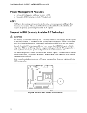
... Instantly Available PC technology, the 5 V standby line for the power supply must be capable of the Standby Power Indicator 16 Intel Desktop Boards D845GLLY and D845GLAD Product Guide Power Management Features • Advanced Configuration and Power Interface (ACPI) • Suspend to RAM (Instantly ... control over the power management and Plug & Play functions of ACPI with Desktop Board D845GLLY or D845GLAD requires an operating system that provides full ACPI support. The use of a computer. The Intel desktop board's standby power indicator, shown in the S3 sleep state, the computer will...
... Instantly Available PC technology, the 5 V standby line for the power supply must be capable of the Standby Power Indicator 16 Intel Desktop Boards D845GLLY and D845GLAD Product Guide Power Management Features • Advanced Configuration and Power Interface (ACPI) • Suspend to RAM (Instantly ... control over the power management and Plug & Play functions of ACPI with Desktop Board D845GLLY or D845GLAD requires an operating system that provides full ACPI support. The use of a computer. The Intel desktop board's standby power indicator, shown in the S3 sleep state, the computer will...

Product Guide
Page 17
... for jumper settings. 17 Fan Connectors Desktop Boards D845GLLY and D845GLAD have two power connectors. Desktop Board Features CAUTION Power supplies used with this board must be able to provide enough standby current to support multiple wake events from the PCI and/or USB buses exceeds power supply capacity, the Intel desktop board may lose register settings stored in...
... for jumper settings. 17 Fan Connectors Desktop Boards D845GLLY and D845GLAD have two power connectors. Desktop Board Features CAUTION Power supplies used with this board must be able to provide enough standby current to support multiple wake events from the PCI and/or USB buses exceeds power supply capacity, the Intel desktop board may lose register settings stored in...
Product Guide
Page 18
The speaker provides audible error code (beep code) information during the Power-On Self-Test (POST). Real-Time Clock Desktop Boards D845GLLY and D845GLAD have a time-of-day clock and 100-year calendar. Battery A battery on the PCI bus is turned off . 18 Speaker ... is asserted, the computer wakes from an ACPI S1 or S3 state. A battery on the Intel desktop board keeps the clock current when the computer is mounted on how to replace the battery. Intel Desktop Boards D845GLLY and D845GLAD Product Guide Wake from PS/2 Keyboard/Mouse PS/2 keyboard/mouse activity wakes the computer...
The speaker provides audible error code (beep code) information during the Power-On Self-Test (POST). Real-Time Clock Desktop Boards D845GLLY and D845GLAD have a time-of-day clock and 100-year calendar. Battery A battery on the PCI bus is turned off . 18 Speaker ... is asserted, the computer wakes from an ACPI S1 or S3 state. A battery on the Intel desktop board keeps the clock current when the computer is mounted on how to replace the battery. Intel Desktop Boards D845GLLY and D845GLAD Product Guide Wake from PS/2 Keyboard/Mouse PS/2 keyboard/mouse activity wakes the computer...
Product Guide
Page 19
...part of the procedures described in this chapter only at an ESD workstation using and modifying electronic equipment. WARNINGS The procedures in this board in a chassis, see Appendix B for using an antistatic wrist strap and a conductive foam pad. Disconnect the computer from its... injury or equipment damage. If such a station is off. 19 2 Installing and Replacing Desktop Board Components This chapter tells you how to: • Install the I/O shield • Install and remove the desktop board • Install and remove a processor • Install and remove memory • Connect ...
...part of the procedures described in this chapter only at an ESD workstation using and modifying electronic equipment. WARNINGS The procedures in this board in a chassis, see Appendix B for using an antistatic wrist strap and a conductive foam pad. Disconnect the computer from its... injury or equipment damage. If such a station is off. 19 2 Installing and Replacing Desktop Board Components This chapter tells you how to: • Install the I/O shield • Install and remove the desktop board • Install and remove a processor • Install and remove memory • Connect ...
Product Guide
Page 20
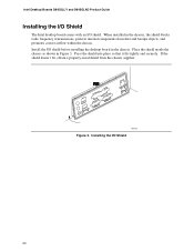
Installing the I /O shield. Press the shield into place so that it fits tightly and securely. OM13621 Figure 3. Intel Desktop Boards D845GLLY and D845GLAD Product Guide Installing the I/O Shield The Intel desktop board comes with an I /O Shield 20 When installed in Figure 3. Place the shield inside the chassis as shown in the chassis, the shield blocks radio frequency ... shield doesn't fit, obtain a properly-sized shield from dust and foreign objects, and promotes correct airflow within the chassis. Install the I/O shield before installing the desktop board in the chassis.
Installing the I /O shield. Press the shield into place so that it fits tightly and securely. OM13621 Figure 3. Intel Desktop Boards D845GLLY and D845GLAD Product Guide Installing the I/O Shield The Intel desktop board comes with an I /O Shield 20 When installed in Figure 3. Place the shield inside the chassis as shown in the chassis, the shield blocks radio frequency ... shield doesn't fit, obtain a properly-sized shield from dust and foreign objects, and promotes correct airflow within the chassis. Install the I/O shield before installing the desktop board in the chassis.
Product Guide
Page 21
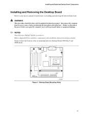
Refer to Appendix B for Desktop Boards D845GLLY and D845GLAD. Failure to your chassis manual for instructions on installing and removing the Intel desktop board. Figure 4 shows the location of the six mounting holes for regulatory requirements and installation instructions and precautions. ...personal injury or equipment damage. ✏ NOTES You will need a Phillips† (#2 bit) screwdriver. Installing and Replacing Desktop Board Components Installing and Removing the Desktop Board Refer to disconnect the power before performing the procedures described here. OM13680 Figure...
Refer to Appendix B for Desktop Boards D845GLLY and D845GLAD. Failure to your chassis manual for instructions on installing and removing the Intel desktop board. Figure 4 shows the location of the six mounting holes for regulatory requirements and installation instructions and precautions. ...personal injury or equipment damage. ✏ NOTES You will need a Phillips† (#2 bit) screwdriver. Installing and Replacing Desktop Board Components Installing and Removing the Desktop Board Refer to disconnect the power before performing the procedures described here. OM13680 Figure...


