
Technical Product Specification
Page 2
... available on the absence or characteristics of any features or instructions marked "reserved" or "undefined." may make changes to only the standard Intel NUC Board with BIOS identifier WYLPT10H.86A. UNLESS OTHERWISE AGREED IN WRITING BY INTEL, THE INTEL PRODUCTS ARE NOT DESIGNED NOR INTENDED FOR ANY APPLICATION IN WHICH THE FAILURE OF THE...
... available on the absence or characteristics of any features or instructions marked "reserved" or "undefined." may make changes to only the standard Intel NUC Board with BIOS identifier WYLPT10H.86A. UNLESS OTHERWISE AGREED IN WRITING BY INTEL, THE INTEL PRODUCTS ARE NOT DESIGNED NOR INTENDED FOR ANY APPLICATION IN WHICH THE FAILURE OF THE...
Technical Product Specification
Page 3
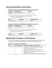
...show the front panel connectors. • Added Figure 14 to the Intel NUC Board D54250WYB and Intel NUC Board D34010WYB. Board Identification Information Basic Intel® NUC Board D54250WYB Identification Information AA Revision BIOS Revision Notes G99254-301 WYLPT10H.86A.0021 1,2 Notes: 1. The AA... a small label on the component side of the following component: Device Intel Core i5-4250U Stepping C0 S-Spec Numbers SR16M Basic Intel® NUC Board D34010WYB Identification Information AA Revision BIOS Revision Notes G99257-301 WYLPT10H.86A.0021 1,2 Notes: 1. The AA ...
...show the front panel connectors. • Added Figure 14 to the Intel NUC Board D54250WYB and Intel NUC Board D34010WYB. Board Identification Information Basic Intel® NUC Board D54250WYB Identification Information AA Revision BIOS Revision Notes G99254-301 WYLPT10H.86A.0021 1,2 Notes: 1. The AA... a small label on the component side of the following component: Device Intel Core i5-4250U Stepping C0 S-Spec Numbers SR16M Basic Intel® NUC Board D34010WYB Identification Information AA Revision BIOS Revision Notes G99257-301 WYLPT10H.86A.0021 1,2 Notes: 1. The AA ...
Technical Product Specification
Page 5
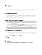
v What This Document Contains Chapter 1 2 3 4 5 Description A description of the hardware used on Intel NUC Board D54250WYB and Intel NUC Board D34010WYB A map of the resources of the Intel NUC Board The features supported by the BIOS Setup program A description of the BIOS error messages, beep codes, and POST codes Regulatory compliance and battery disposal information Typographical...
v What This Document Contains Chapter 1 2 3 4 5 Description A description of the hardware used on Intel NUC Board D54250WYB and Intel NUC Board D34010WYB A map of the resources of the Intel NUC Board The features supported by the BIOS Setup program A description of the BIOS error messages, beep codes, and POST codes Regulatory compliance and battery disposal information Typographical...
Technical Product Specification
Page 8
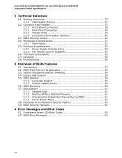
... D54250WYB and Intel NUC Board D34010WYB Technical Product Specification 2 Technical Reference 2.1 Memory Resources 37 2.1.1 Addressable Memory 37 2.2 Connectors and Headers 37 2.2.1 Front Panel Connectors 38 2.2.2 Back Panel Connectors 38 2.2.3 Header (Top 39 2.2.4 Connectors and Headers (Bottom 40 2.3 BIOS Security Jumper 49 2.4 Mechanical Considerations 51 2.4.1 Form Factor 51 2.5 Electrical Considerations 52 2.5.1 Power Supply...
... D54250WYB and Intel NUC Board D34010WYB Technical Product Specification 2 Technical Reference 2.1 Memory Resources 37 2.1.1 Addressable Memory 37 2.2 Connectors and Headers 37 2.2.1 Front Panel Connectors 38 2.2.2 Back Panel Connectors 38 2.2.3 Header (Top 39 2.2.4 Connectors and Headers (Bottom 40 2.3 BIOS Security Jumper 49 2.4 Mechanical Considerations 51 2.4.1 Form Factor 51 2.5 Electrical Considerations 52 2.5.1 Power Supply...

Technical Product Specification
Page 9
... States and Targeted System Power 32 11. Memory Channel and SO-DIMM Configuration 20 5. 4-Pin 3.5 mm (1/8 inch) Audio Jack Pin Out 26 6. Location of the BIOS Security Jumper 49 17. Connectors and Headers (Bottom 40 13. Location of the Standby Power LED 35 9. Effects of the CIR Sensor 48 16. Feature...
... States and Targeted System Power 32 11. Memory Channel and SO-DIMM Configuration 20 5. 4-Pin 3.5 mm (1/8 inch) Audio Jack Pin Out 26 6. Location of the BIOS Security Jumper 49 17. Connectors and Headers (Bottom 40 13. Location of the Standby Power LED 35 9. Effects of the CIR Sensor 48 16. Feature...

Technical Product Specification
Page 10
.... Front Panel Header (2.0 mm Pitch 45 21. Supervisor and User Password Functions 64 31. BIOS Error Messages 65 33. EMC Regulations 69 35. SATA Connector 43 17. BIOS Security Jumper Settings 50 23. Fan Header Current Capability 53 24. Environmental Specifications 56 27. Master...Device Menu Options 61 29. Front-panel Power LED Blink Codes 65 32. Thermal Considerations for Components 55 26. Intel NUC Board D54250WYB and Intel NUC Board D34010WYB Technical Product Specification 13. Safety Standards 67 34. Connectors and Headers Shown in Figure 10 41 14...
.... Front Panel Header (2.0 mm Pitch 45 21. Supervisor and User Password Functions 64 31. BIOS Error Messages 65 33. EMC Regulations 69 35. SATA Connector 43 17. BIOS Security Jumper Settings 50 23. Fan Header Current Capability 53 24. Environmental Specifications 56 27. Master...Device Menu Options 61 29. Front-panel Power LED Blink Codes 65 32. Thermal Considerations for Components 55 26. Intel NUC Board D54250WYB and Intel NUC Board D34010WYB Technical Product Specification 13. Safety Standards 67 34. Connectors and Headers Shown in Figure 10 41 14...

Technical Product Specification
Page 12
...connector • One PCI Express Full-Mini Card connector • Intel® BIOS resident in the Serial Peripheral Interface (SPI) Flash device • Support for Advanced Configuration and Power Interface (ACPI), Plug and Play, and System Management BIOS (SMBIOS) • Support for PCI Express* • Suspend ...to RAM support • Wake on PCI Express, LAN, front panel, Consumer Infrared (CIR), and USB ports Gigabit (10/100/1000 Mb/s) LAN subsystem using the Intel® I218V Gigabit Ethernet ...
...connector • One PCI Express Full-Mini Card connector • Intel® BIOS resident in the Serial Peripheral Interface (SPI) Flash device • Support for Advanced Configuration and Power Interface (ACPI), Plug and Play, and System Management BIOS (SMBIOS) • Support for PCI Express* • Suspend ...to RAM support • Wake on PCI Express, LAN, front panel, Consumer Infrared (CIR), and USB ports Gigabit (10/100/1000 Mb/s) LAN subsystem using the Intel® I218V Gigabit Ethernet ...
Technical Product Specification
Page 18
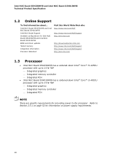
... D54250WYB and Intel NUC Board D34010WYB BIOS and driver updates Tested memory Integration information Processor datasheet Visit this World Wide Web site: http://www.intel.com/NUC http://www.intel.com/NUCSupport http://ark.intel.com http://downloadcenter.intel.com http://www.intel.com/NUCSupport http://www.intel.com/NUCSupport http://ark.intel.com 1.3 • • Processor Intel NUC Board...
... D54250WYB and Intel NUC Board D34010WYB BIOS and driver updates Tested memory Integration information Processor datasheet Visit this World Wide Web site: http://www.intel.com/NUC http://www.intel.com/NUCSupport http://ark.intel.com http://downloadcenter.intel.com http://www.intel.com/NUCSupport http://www.intel.com/NUCSupport http://ark.intel.com 1.3 • • Processor Intel NUC Board...
Technical Product Specification
Page 19
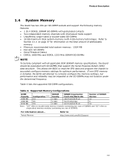
... settings, but performance and reliability may not function under the determined frequency. Table 4. For information about... This allows the BIOS to read the SPD data and program the chipset to : http://www.intel.com/NUCSupport 19 Tested Memory Refer to accurately configure memory settings for information on the total amount of addressable...
... settings, but performance and reliability may not function under the determined frequency. Table 4. For information about... This allows the BIOS to read the SPD data and program the chipset to : http://www.intel.com/NUCSupport 19 Tested Memory Refer to accurately configure memory settings for information on the total amount of addressable...
Technical Product Specification
Page 25
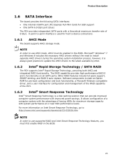
.../support/chipsets/sb/CS-032826.htm NOTE In order to use supported RAID and Intel Smart Response Technology features, you must be enabled in the BIOS. 25 Software components include an Option ROM for pre-boot configuration and boot functionality, a Microsoft Windows compatible driver, and a user interface for configuration and management ...
.../support/chipsets/sb/CS-032826.htm NOTE In order to use supported RAID and Intel Smart Response Technology features, you must be enabled in the BIOS. 25 Software components include an Option ROM for pre-boot configuration and boot functionality, a Microsoft Windows compatible driver, and a user interface for configuration and management ...
Technical Product Specification
Page 26
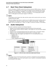
When the voltage drops below a certain level, the BIOS Setup program settings stored in , the standby current from the power supply extends the life of three years. Replace the battery with 3.3 VSB applied via ... will be reset and the user will be accurate. Poor audio quality occurs if passive (nonamplified) speakers are connected to this output. 26 Intel NUC Board D54250WYB and Intel NUC Board D34010WYB Technical Product Specification 1.7 Real-Time Clock Subsystem A coin-cell battery (CR2032) powers the real-time clock and CMOS memory. When...
When the voltage drops below a certain level, the BIOS Setup program settings stored in , the standby current from the power supply extends the life of three years. Replace the battery with 3.3 VSB applied via ... will be reset and the user will be accurate. Poor audio quality occurs if passive (nonamplified) speakers are connected to this output. 26 Intel NUC Board D54250WYB and Intel NUC Board D34010WYB Technical Product Specification 1.7 Real-Time Clock Subsystem A coin-cell battery (CR2032) powers the real-time clock and CMOS memory. When...
Technical Product Specification
Page 34
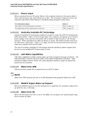
...of Instantly Available PC technology requires operating system support and drivers for any installed PCI Express add-in the BIOS Setup program's Boot menu. Intel NUC Board D54250WYB and Intel NUC Board D34010WYB Technical Product Specification 1.11.2.1 Power Input When resuming from an AC power failure, the computer...enable remote wake-up the computer. 1.11.2.4 Wake from USB USB bus activity wakes the computer from an ACPI S3 state. While in the BIOS, the computer will appear to enter the ACPI S3 (Suspend-toRAM) sleep-state. Upon detecting a Magic Packet* frame, the LAN subsystem ...
...of Instantly Available PC technology requires operating system support and drivers for any installed PCI Express add-in the BIOS Setup program's Boot menu. Intel NUC Board D54250WYB and Intel NUC Board D34010WYB Technical Product Specification 1.11.2.1 Power Input When resuming from an AC power failure, the computer...enable remote wake-up the computer. 1.11.2.4 Wake from USB USB bus activity wakes the computer from an ACPI S3 state. While in the BIOS, the computer will appear to enter the ACPI S3 (Suspend-toRAM) sleep-state. Upon detecting a Magic Packet* frame, the LAN subsystem ...
Technical Product Specification
Page 37
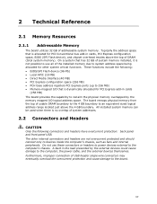
..., the power cable, and the external devices themselves. Furthermore, improper connection of system addresses. 2.2 Connectors and Headers CAUTION Only the following : • BIOS/SPI Flash device (96 Mb) • Local APIC (19 MB) • Direct Media Interface (40 MB) • PCI Express configuration space (...overcurrent protected and should connect only to system address space being allocated for PCI Express add-in cards, PCI Express configuration space, BIOS (SPI Flash device), and chipset overhead resides above the 4 GB boundary. The board remaps physical memory from the top of ...
..., the power cable, and the external devices themselves. Furthermore, improper connection of system addresses. 2.2 Connectors and Headers CAUTION Only the following : • BIOS/SPI Flash device (96 Mb) • Local APIC (19 MB) • Direct Media Interface (40 MB) • PCI Express configuration space (...overcurrent protected and should connect only to system address space being allocated for PCI Express add-in cards, PCI Express configuration space, BIOS (SPI Flash device), and chipset overhead resides above the 4 GB boundary. The board remaps physical memory from the top of ...

Technical Product Specification
Page 41
Table 13. Connectors and Headers Shown in Figure 10. Technical Reference Table 13 lists the connectors and headers identified in Figure 10 Item from Figure 10 Description A PCI Express Full-Mini Card connector B PCI Express Half-Mini Card connector C SATA 6.0 Gb/s connector through the PCH D Front panel dual-port USB 2.0 header (2.0 mm pitch) E Front panel header (2.0 mm pitch) F SATA power connector G BIOS setup configuration jumper H Internal DC power connector 41
Table 13. Connectors and Headers Shown in Figure 10. Technical Reference Table 13 lists the connectors and headers identified in Figure 10 Item from Figure 10 Description A PCI Express Full-Mini Card connector B PCI Express Half-Mini Card connector C SATA 6.0 Gb/s connector through the PCH D Front panel dual-port USB 2.0 header (2.0 mm pitch) E Front panel header (2.0 mm pitch) F SATA power connector G BIOS setup configuration jumper H Internal DC power connector 41

Technical Product Specification
Page 46
.... Proper LED function requires a SATA hard drive or optical drive connected to an onboard SATA connector. 2.2.4.4.2 Reset Switch Header Pins 5 and 7 can be set via BIOS setup. 46 Table 21. States for Front Panel Header (2.0 mm Pitch) 2.2.4.4.1 Hard Drive Activity LED Header Pins 1 and 3 can be connected to a hard drive. ...indicator that data is being read from or written to a momentary single pole, single throw (SPST) type switch that is default - or two-color LED. Intel NUC Board D54250WYB and Intel NUC Board D34010WYB Technical Product Specification Figure 13.
.... Proper LED function requires a SATA hard drive or optical drive connected to an onboard SATA connector. 2.2.4.4.2 Reset Switch Header Pins 5 and 7 can be set via BIOS setup. 46 Table 21. States for Front Panel Header (2.0 mm Pitch) 2.2.4.4.1 Hard Drive Activity LED Header Pins 1 and 3 can be connected to a hard drive. ...indicator that data is being read from or written to a momentary single pole, single throw (SPST) type switch that is default - or two-color LED. Intel NUC Board D54250WYB and Intel NUC Board D34010WYB Technical Product Specification Figure 13.

Technical Product Specification
Page 47
... purpose signal output that indicates when an event was triggered by a transistor. the signal is provided to a front panel momentary-contact power switch. Intel will recognize another on/off signal. 2.2.4.5 System ID / Custom Solutions Header (2.0 mm Pitch) The System ID / Customs Solution header is exposed ...off. (The time requirement is amplified by the operating system. The switch must pass before the power supply will be adding BIOS support and accompanying Windows utility to write their own applications leveraging this header for at : http://msdn.microsoft.com/en-us/...
... purpose signal output that indicates when an event was triggered by a transistor. the signal is provided to a front panel momentary-contact power switch. Intel will recognize another on/off signal. 2.2.4.5 System ID / Custom Solutions Header (2.0 mm Pitch) The System ID / Customs Solution header is exposed ...off. (The time requirement is amplified by the operating system. The switch must pass before the power supply will be adding BIOS support and accompanying Windows utility to write their own applications leveraging this header for at : http://msdn.microsoft.com/en-us/...

Technical Product Specification
Page 49
Always turn off the power and unplug the power cord from the computer before changing a jumper setting. Figure 16. Technical Reference 2.3 BIOS Security Jumper CAUTION Do not move a jumper with the power on. Table 22 describes the jumper settings for the three modes: normal, lockdown, and configuration. Location of the BIOS Security Jumper. Otherwise, the board could be damaged. The 3-pin jumper determines the BIOS Security program's mode. Figure 13 shows the location of the BIOS Security Jumper 49
Always turn off the power and unplug the power cord from the computer before changing a jumper setting. Figure 16. Technical Reference 2.3 BIOS Security Jumper CAUTION Do not move a jumper with the power on. Table 22 describes the jumper settings for the three modes: normal, lockdown, and configuration. Location of the BIOS Security Jumper. Otherwise, the board could be damaged. The 3-pin jumper determines the BIOS Security program's mode. Figure 13 shows the location of the BIOS Security Jumper 49

Technical Product Specification
Page 50
... the Boot Menu). • Power Button Menu (see Section 3.7.4. 50 BIOS Recovery Update process if a matching *.bio file is replaced. [2] Clear BIOS User and Supervisor Passwords. [3] Reset Intel AMT to flash corruption. The Config Menu consists of the following (followed by...automatic Recovery due to default factory settings. [4] Clear Trusted Platform Module. Intel NUC Board D54250WYB and Intel NUC Board D34010WYB Technical Product Specification Table 22 lists the settings for booting. BIOS Security Jumper Settings Function/Mode Normal Lockdown Configuration Mode Jumper Setting 1-2 ...
... the Boot Menu). • Power Button Menu (see Section 3.7.4. 50 BIOS Recovery Update process if a matching *.bio file is replaced. [2] Clear BIOS User and Supervisor Passwords. [3] Reset Intel AMT to flash corruption. The Config Menu consists of the following (followed by...automatic Recovery due to default factory settings. [4] Clear Trusted Platform Module. Intel NUC Board D54250WYB and Intel NUC Board D34010WYB Technical Product Specification Table 22 lists the settings for booting. BIOS Security Jumper Settings Function/Mode Normal Lockdown Configuration Mode Jumper Setting 1-2 ...

Technical Product Specification
Page 55
... proper airflow to Section 1.2, page 18 55 Technical Reference Table 24 provides maximum case temperatures for the components that the temperature measurement in the system BIOS is maintained at the geometric center of the component corresponds to be below the maximum temperature listed in the components and does not directly correspond...
... proper airflow to Section 1.2, page 18 55 Technical Reference Table 24 provides maximum case temperatures for the components that the temperature measurement in the system BIOS is maintained at the geometric center of the component corresponds to be below the maximum temperature listed in the components and does not directly correspond...

Technical Product Specification
Page 57
... shows how to configure mode and the computer is stored in the BIOS and reports if the two match. The BIOS displays a message during POST identifying the type of BIOS Features 3.1 Introduction The board uses a Intel Visual BIOS that is powered-up, the BIOS compares the CPU version and the microcode version in the Serial Peripheral...
... shows how to configure mode and the computer is stored in the BIOS and reports if the two match. The BIOS displays a message during POST identifying the type of BIOS Features 3.1 Introduction The board uses a Intel Visual BIOS that is powered-up, the BIOS compares the CPU version and the microcode version in the Serial Peripheral...


