
Technical Product Specification for Intel Desktop Board D2700DC
Page 12
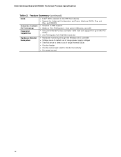
Feature Summary (continued) BIOS • Intel® BIOS (resident in the SPI Flash device) • Support for Advanced Configuration and Power Interface (ACPI), Plug and Play, and SMBIOS Instantly Available • Suspend to RAM support PC Technology • Wake on ...controller • Voltage sense to detect out of range power supply voltages • Thermal sense to detect out of range thermal values • One fan header • One fan sense input used to monitor fan activity • Fan speed control 12 Intel Desktop Board D2700DC Technical Product Specification Table 2.
Feature Summary (continued) BIOS • Intel® BIOS (resident in the SPI Flash device) • Support for Advanced Configuration and Power Interface (ACPI), Plug and Play, and SMBIOS Instantly Available • Suspend to RAM support PC Technology • Wake on ...controller • Voltage sense to detect out of range power supply voltages • Thermal sense to detect out of range thermal values • One fan header • One fan sense input used to monitor fan activity • Fan speed control 12 Intel Desktop Board D2700DC Technical Product Specification Table 2.
Technical Product Specification for Intel Desktop Board D2700DC
Page 16
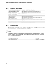
.../support/motherboards/desktop/sb/CS025414.htm http://www.intel.com/support/go/buildit 1.3 Processor The board has a passively-cooled, soldered-down Dual-Core Intel Atom processor with integrated graphics and integrated memory controller. Intel Desktop Board D2700DC Technical Product Specification 1.2 Online Support To find information about Power supply connectors Refer to be passively cooled in a properly...
.../support/motherboards/desktop/sb/CS025414.htm http://www.intel.com/support/go/buildit 1.3 Processor The board has a passively-cooled, soldered-down Dual-Core Intel Atom processor with integrated graphics and integrated memory controller. Intel Desktop Board D2700DC Technical Product Specification 1.2 Online Support To find information about Power supply connectors Refer to be passively cooled in a properly...
Technical Product Specification for Intel Desktop Board D2700DC
Page 22
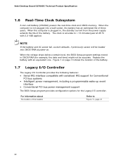
Intel Desktop Board D2700DC Technical Product Specification 1.6 Real-Time Clock Subsystem A coin-cell battery (CR2032) powers the real-time clock and CMOS memory. When the computer is plugged in CMOS RAM (for the Legacy I /O Controller provides the following ...a certain level, the BIOS Setup program settings stored in , the standby current from the power supply extends the life of the battery. 1.7 Legacy I/O Controller The Legacy I /O controller. NOTE If the battery and AC power fail, custom defaults, if previously saved, will be accurate. For information about The location of...
Intel Desktop Board D2700DC Technical Product Specification 1.6 Real-Time Clock Subsystem A coin-cell battery (CR2032) powers the real-time clock and CMOS memory. When the computer is plugged in CMOS RAM (for the Legacy I /O Controller provides the following ...a certain level, the BIOS Setup program settings stored in , the standby current from the power supply extends the life of the battery. 1.7 Legacy I/O Controller The Legacy I /O controller. NOTE If the battery and AC power fail, custom defaults, if previously saved, will be accurate. For information about The location of...
Technical Product Specification for Intel Desktop Board D2700DC
Page 30
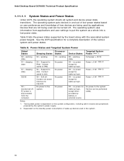
... into a low-power state. No power to disk. Service can be performed safely. Intel Desktop Board D2700DC Technical Product Specification 1.11.1.1 System States and Power States Under ACPI, the operating system directs all system and device power state transitions. The... saved to the system. Total system power is required. Soft off . working S3 - Notes: 1. sleeping state G2/S5 S0 - Full power > 30 W Power < 5 W (Note 2) Power < 5 W (Note 2) Power < 5 W (Note 2) G3 - Table 8 lists the power states supported by the system's power supply. 2. working state.
... into a low-power state. No power to disk. Service can be performed safely. Intel Desktop Board D2700DC Technical Product Specification 1.11.1.1 System States and Power States Under ACPI, the operating system directs all system and device power state transitions. The... saved to the system. Total system power is required. Soft off . working S3 - Notes: 1. sleeping state G2/S5 S0 - Full power > 30 W Power < 5 W (Note 2) Power < 5 W (Note 2) Power < 5 W (Note 2) G3 - Table 8 lists the power states supported by the system's power supply. 2. working state.

Technical Product Specification for Intel Desktop Board D2700DC
Page 46
Table 19. Intel Desktop Board D2700DC Technical Product Specification 2.2.2.3 Power Supply Connector The board has a 2 x 12 power connector (see Table 19). This board requires a TFX12V or SFX12V power supply. Power Connector Pin 1 2 3 4 5 6 7 8 9 10 11 12 Signal Name +3.3 V +3.3 V Ground +5 V Ground +5 V Ground PWRGD (Power Good) +5 V (Standby) +12 V +12 V No connect Pin Signal Name 13 +3.3 V 14 -12 V 15 Ground 16 PS-ON# (power supply remote on/off) 17 Ground 18 Ground 19 Ground 20 No connect 21 +5 V 22 +5 V 23 +5 V 24 Ground 46
Table 19. Intel Desktop Board D2700DC Technical Product Specification 2.2.2.3 Power Supply Connector The board has a 2 x 12 power connector (see Table 19). This board requires a TFX12V or SFX12V power supply. Power Connector Pin 1 2 3 4 5 6 7 8 9 10 11 12 Signal Name +3.3 V +3.3 V Ground +5 V Ground +5 V Ground PWRGD (Power Good) +5 V (Standby) +12 V +12 V No connect Pin Signal Name 13 +3.3 V 14 -12 V 15 Ground 16 PS-ON# (power supply remote on/off) 17 Ground 18 Ground 19 Ground 20 No connect 21 +5 V 22 +5 V 23 +5 V 24 Ground 46

Technical Product Specification for Intel Desktop Board D2700DC
Page 48
... or off. (The time requirement is due to internal debounce circuitry on the board.) At least two seconds must pass before the power supply circuitry will recognize another on/off /hibernate (S5/S4) Blinking Sleeping (S3) Steady Green Running/Away (S0) NOTE The LED ...built with a dual-color front panel power LED can also use alternate color state options. 2.2.2.4.4 Power Switch Header Pins 6 and 8 can be connected to a single- The switch must pull the SW_ON# pin to ground for a single-color LED. Intel Desktop Board D2700DC Technical Product Specification 2.2.2.4.1 Hard Drive Activity...
... or off. (The time requirement is due to internal debounce circuitry on the board.) At least two seconds must pass before the power supply circuitry will recognize another on/off /hibernate (S5/S4) Blinking Sleeping (S3) Steady Green Running/Away (S0) NOTE The LED ...built with a dual-color front panel power LED can also use alternate color state options. 2.2.2.4.4 Power Switch Header Pins 6 and 8 can be connected to a single- The switch must pull the SW_ON# pin to ground for a single-color LED. Intel Desktop Board D2700DC Technical Product Specification 2.2.2.4.1 Hard Drive Activity...

Technical Product Specification for Intel Desktop Board D2700DC
Page 55
...section can also be specified for optimal thermal design. Defined as (TJ - Note: Heat source must be used in conjunction with either a power supply fan or a built-in system fan. This material fills the air gaps and voids, and enhances the transfer of a passive heatsink. Technical.... Passive system environment describes a chassis with the Thermal and Mechanical Design Guide (TMDG) published for Components Component Intel Atom processor Processor voltage regulator area Intel NM10 Express Chipset Memory SO-DIMM Maximum Case Temperature 100 oC 85 oC 113 oC 85 oC For information about...
...section can also be specified for optimal thermal design. Defined as (TJ - Note: Heat source must be used in conjunction with either a power supply fan or a built-in system fan. This material fills the air gaps and voids, and enhances the transfer of a passive heatsink. Technical.... Passive system environment describes a chassis with the Thermal and Mechanical Design Guide (TMDG) published for Components Component Intel Atom processor Processor voltage regulator area Intel NM10 Express Chipset Memory SO-DIMM Maximum Case Temperature 100 oC 85 oC 113 oC 85 oC For information about...
Technical Product Specification for Intel Desktop Board D2700DC
Page 58
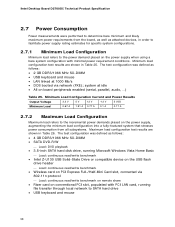
... Minimum load refers to the power demand placed on the power supply when using a bare system configuration with PCI LAN card, running Microsoft Windows Vista Home Basic Load: continuous read/write benchmark • Intel Z-U130 USB Solid-State Drive... on board peripherals enabled (serial, parallel, audio, ...) Table 25. Intel Desktop Board D2700DC Technical Product Specification 2.7 Power Consumption Power measurements were performed to determine bare minimum and likely maximum power requirements from all subsystems. Maximum load configuration test results are shown in Table...
... Minimum load refers to the power demand placed on the power supply when using a bare system configuration with PCI LAN card, running Microsoft Windows Vista Home Basic Load: continuous read/write benchmark • Intel Z-U130 USB Solid-State Drive... on board peripherals enabled (serial, parallel, audio, ...) Table 25. Intel Desktop Board D2700DC Technical Product Specification 2.7 Power Consumption Power measurements were performed to determine bare minimum and likely maximum power requirements from all subsystems. Maximum load configuration test results are shown in Table...
Product Guide for Intel Desktop Board D2700DC
Page 5
... Support 10 Desktop Board Components 11 Processor ...13 System Memory 13 Graphics Support 14 Integrated Graphics Subsystem 14 External Graphics 14 Intel® NM10 Express Chipset 15 Onboard Audio Subsystem 15 Legacy Input/Output (I/O) Controller 16 LAN Subsystem 17 USB 2.0 Support... Battery ...22 Real-Time Clock 22 2 Installing and Replacing Desktop Board Components Before You Begin 23 Installation Precautions 25 Prevent Power Supply Overload 25 Observe Safety and Regulatory Requirements 25 Installing the I/O Shield 26 Installing and Removing the Desktop Board 27 Installing and...
... Support 10 Desktop Board Components 11 Processor ...13 System Memory 13 Graphics Support 14 Integrated Graphics Subsystem 14 External Graphics 14 Intel® NM10 Express Chipset 15 Onboard Audio Subsystem 15 Legacy Input/Output (I/O) Controller 16 LAN Subsystem 17 USB 2.0 Support... Battery ...22 Real-Time Clock 22 2 Installing and Replacing Desktop Board Components Before You Begin 23 Installation Precautions 25 Prevent Power Supply Overload 25 Observe Safety and Regulatory Requirements 25 Installing the I/O Shield 26 Installing and Removing the Desktop Board 27 Installing and...

Product Guide for Intel Desktop Board D2700DC
Page 7
... Jack Support 15 4. EMC Regulations 59 19. Intel Desktop Board D2700DC China RoHS Material Self Declaration Table............58 Tables 1. Jumper Settings for AC '97 Audio 34 7. ENERGY STAR Requirements 64 vii Contents Figures 1. Installing System Memory 28 8. Installing a PCI Express Mini Card 31 10. Connecting Power Supply Cables 38 14. LAN Status LEDs 17...
... Jack Support 15 4. EMC Regulations 59 19. Intel Desktop Board D2700DC China RoHS Material Self Declaration Table............58 Tables 1. Jumper Settings for AC '97 Audio 34 7. ENERGY STAR Requirements 64 vii Contents Figures 1. Installing System Memory 28 8. Installing a PCI Express Mini Card 31 10. Connecting Power Supply Cables 38 14. LAN Status LEDs 17...

Product Guide for Intel Desktop Board D2700DC
Page 23
Some circuitry on the board can continue to internal headers • Connect system fan and power supply cables • Set the BIOS configuration jumper • Clear passwords • Replace the battery Before You Begin CAUTION The procedures in this chapter assume ... system memory • Connect SATA drives • Install a PCI Express Mini Card • Install an Intel Z-U130 USB Solid-State Drive or compatible device • Connect to operate even though the front panel power button is not available, you can provide some ESD protection by wearing an antistatic wrist strap and...
Some circuitry on the board can continue to internal headers • Connect system fan and power supply cables • Set the BIOS configuration jumper • Clear passwords • Replace the battery Before You Begin CAUTION The procedures in this chapter assume ... system memory • Connect SATA drives • Install a PCI Express Mini Card • Install an Intel Z-U130 USB Solid-State Drive or compatible device • Connect to operate even though the front panel power button is not available, you can provide some ESD protection by wearing an antistatic wrist strap and...

Product Guide for Intel Desktop Board D2700DC
Page 25
...If you do not follow these instructions and the instructions provided by chassis and module suppliers, you install and test the Intel Desktop Board, observe all warnings and cautions that instruct you to refer computer servicing to qualified technical personnel. Installing and ...Regulatory Requirements Read and adhere to Appendix B for safety and regulatory requirements. 25 To avoid injury, be careful of the power supply. To avoid overloading the power supply, make sure that the calculated total current loads of all the modules within the computer is less than the output current rating...
...If you do not follow these instructions and the instructions provided by chassis and module suppliers, you install and test the Intel Desktop Board, observe all warnings and cautions that instruct you to refer computer servicing to qualified technical personnel. Installing and ...Regulatory Requirements Read and adhere to Appendix B for safety and regulatory requirements. 25 To avoid injury, be careful of the power supply. To avoid overloading the power supply, make sure that the calculated total current loads of all the modules within the computer is less than the output current rating...

Product Guide for Intel Desktop Board D2700DC
Page 38
Connect the main power supply cable to the board or the system may result in "Before You Begin" on page 23. 2. Intel Desktop Board D2700DC Product Guide Connecting a Power Supply CAUTION Failure to connect an appropriate power supply to the Desktop Board may not function properly. Connecting Power Supply Cables 1. Figure 13. Observe the precautions in damage to the 2 x 12 pin connector. 38 Figure 13 shows the location of the power connector.
Connect the main power supply cable to the board or the system may result in "Before You Begin" on page 23. 2. Intel Desktop Board D2700DC Product Guide Connecting a Power Supply CAUTION Failure to connect an appropriate power supply to the Desktop Board may not function properly. Connecting Power Supply Cables 1. Figure 13. Observe the precautions in damage to the 2 x 12 pin connector. 38 Figure 13 shows the location of the power connector.

Product Guide for Intel Desktop Board D2700DC
Page 41
Installing and Replacing Desktop Board Components Replacing the Battery A coin-cell battery powers the Desktop Board's real-time clock and CMOS memory. CAUTION Risk of three years. Brukte batterier bør kastes i henhold til gjeldende miljølovgivning. VARO R&#... battery has an estimated life of explosion if the battery is replaced with 3.3 VSB applied. The clock is plugged in, the standby current from the power supply extends the life of the battery. Figure 15 on hävitettävä paikallisten ympäristömääräysten mukaisesti. PRÉ...
Installing and Replacing Desktop Board Components Replacing the Battery A coin-cell battery powers the Desktop Board's real-time clock and CMOS memory. CAUTION Risk of three years. Brukte batterier bør kastes i henhold til gjeldende miljølovgivning. VARO R&#... battery has an estimated life of explosion if the battery is replaced with 3.3 VSB applied. The clock is plugged in, the standby current from the power supply extends the life of the battery. Figure 15 on hävitettävä paikallisten ympäristömääräysten mukaisesti. PRÉ...

Product Guide for Intel Desktop Board D2700DC
Page 61
... • Mounting, grounding, and bonding requirements • Keying connectors when mating the wrong connectors could be hazardous If the power supply and other modules or peripherals, as applicable, have passed Class B EMC testing and are not Class B EMC compliant before ...are marked accordingly. Regulatory Compliance Korea Class B Statement Korea Class B Statement translation: This equipment is for the host chassis, power supply, and other modules: • Product certifications or lack of the newly completed computer. 61 Ensure Electromagnetic Compatibility (EMC) Compliance ...
... • Mounting, grounding, and bonding requirements • Keying connectors when mating the wrong connectors could be hazardous If the power supply and other modules or peripherals, as applicable, have passed Class B EMC testing and are not Class B EMC compliant before ...are marked accordingly. Regulatory Compliance Korea Class B Statement Korea Class B Statement translation: This equipment is for the host chassis, power supply, and other modules: • Product certifications or lack of the newly completed computer. 61 Ensure Electromagnetic Compatibility (EMC) Compliance ...

Product Guide for Intel Desktop Board D2700DC
Page 63
... properly CE marked, a supplier's Declaration of this product guide demonstrates compliance with electromagnetic interference (EMI) requirements. If the chassis and other directives, such as the power supply, peripheral drives, wiring, and cables; Wiring and cables must also be obtained. Regulatory Compliance Chassis- The FCC Class B logo for home or office use . Typical...
... properly CE marked, a supplier's Declaration of this product guide demonstrates compliance with electromagnetic interference (EMI) requirements. If the chassis and other directives, such as the power supply, peripheral drives, wiring, and cables; Wiring and cables must also be obtained. Regulatory Compliance Chassis- The FCC Class B logo for home or office use . Typical...


