

Technical product specification
Page 2
... latest specifications before placing your product order. INFORMATION IN THIS DOCUMENT IS PROVIDED IN CONNECTION WITH INTEL® PRODUCTS. Contact your local Intel sales office or your distributor to only the standard Intel® Desktop Board D2550MUD2 with BIOS identifier MUCDT10N.86A. and/or other countries. * Other names and brands may cause the product to...
... latest specifications before placing your product order. INFORMATION IN THIS DOCUMENT IS PROVIDED IN CONNECTION WITH INTEL® PRODUCTS. Contact your local Intel sales office or your distributor to only the standard Intel® Desktop Board D2550MUD2 with BIOS identifier MUCDT10N.86A. and/or other countries. * Other names and brands may cause the product to...

Technical product specification
Page 3
... for the latest documentation. iii Board Identification Information Basic Desktop Board D2550MUD2 Identification Information AA Revision BIOS Revision Notes G73892-600 MUCDT10N.86A.0069 1,2 Notes: 1. The AA number is found on a small label on this AA revision consists of the board. 2. The Intel® NM10 Express Chipset and D2550 processor used on the...
... for the latest documentation. iii Board Identification Information Basic Desktop Board D2550MUD2 Identification Information AA Revision BIOS Revision Notes G73892-600 MUCDT10N.86A.0069 1,2 Notes: 1. The AA number is found on a small label on this AA revision consists of the board. 2. The Intel® NM10 Express Chipset and D2550 processor used on the...

Technical product specification
Page 5
... of the resources of the board The features supported by the BIOS Setup program A description of the BIOS error messages, beep codes, and POST codes Regulatory compliance and battery disposal information Typographical Conventions This section contains information about the Intel Desktop Board D2550MUD2 and its components to help you avoid damaging hardware or losing...
... of the resources of the board The features supported by the BIOS Setup program A description of the BIOS error messages, beep codes, and POST codes Regulatory compliance and battery disposal information Typographical Conventions This section contains information about the Intel Desktop Board D2550MUD2 and its components to help you avoid damaging hardware or losing...
Technical product specification
Page 7
... Feature Summary 11 1.1.2 Board Layout 13 1.1.3 Block Diagram 15 1.2 Online Support 16 1.3 Processor 16 1.3.1 Intel® D2550 Graphics Subsystem 17 1.4 System Memory 18 1.5 Intel® NM10 Express Chipset 20 1.5.2 USB 22 1.5.3 SATA Support 22 1.6 Real-Time Clock Subsystem 23 1.7...Map 37 2.1.1 Addressable Memory 37 2.2 Connectors and Headers 40 2.2.1 Back Panel 41 2.2.2 Component-side Connectors and Headers 43 2.3 BIOS Configuration Jumper Block 55 2.4 Mechanical Considerations 57 2.4.1 Form Factor 57 2.5 Electrical Considerations 58 2.5.1 Fan Header Current Capability 58 ...
... Feature Summary 11 1.1.2 Board Layout 13 1.1.3 Block Diagram 15 1.2 Online Support 16 1.3 Processor 16 1.3.1 Intel® D2550 Graphics Subsystem 17 1.4 System Memory 18 1.5 Intel® NM10 Express Chipset 20 1.5.2 USB 22 1.5.3 SATA Support 22 1.6 Real-Time Clock Subsystem 23 1.7...Map 37 2.1.1 Addressable Memory 37 2.2 Connectors and Headers 40 2.2.1 Back Panel 41 2.2.2 Component-side Connectors and Headers 43 2.3 BIOS Configuration Jumper Block 55 2.4 Mechanical Considerations 57 2.4.1 Form Factor 57 2.5 Electrical Considerations 58 2.5.1 Fan Header Current Capability 58 ...

Technical product specification
Page 8
Intel Desktop Board D2550MUD2 Technical Product Specification 2.7 Power Consumption 63 2.7.1 Minimum Load Configuration 63 2.7.2 Maximum Load Configuration 63 2.8 Reliability 64 2.9 Environmental 64 3 Overview of BIOS Features 3.1 Introduction 65 3.2 BIOS Flash Memory Organization 66 3.3 Resource Configuration 66 3.3.1 PCI* Autoconfiguration 66 3.4 System Management BIOS (SMBIOS 67 3.5 Legacy USB Support 68 3.6 BIOS Updates 69 3.6.1 BIOS Recovery 69 3.6.2 Custom Splash Screen 70...
Intel Desktop Board D2550MUD2 Technical Product Specification 2.7 Power Consumption 63 2.7.1 Minimum Load Configuration 63 2.7.2 Maximum Load Configuration 63 2.8 Reliability 64 2.9 Environmental 64 3 Overview of BIOS Features 3.1 Introduction 65 3.2 BIOS Flash Memory Organization 66 3.3 Resource Configuration 66 3.3.1 PCI* Autoconfiguration 66 3.4 System Management BIOS (SMBIOS 67 3.5 Legacy USB Support 68 3.6 BIOS Updates 69 3.6.1 BIOS Recovery 69 3.6.2 Custom Splash Screen 70...
Technical product specification
Page 9
Back Panel Audio Connectors 27 6. Location of the BIOS Configuration Jumper Block 55 16. Board Dimensions 57 17. ...13 2. Memory Channel and SO-DIMM Configuration 19 4. I/O Shield Reference Diagram 42 11. Fan Location Guide for Intel HD Audio 48 21. LVDS Data Connector 46 14. LVDS Inverter Power Voltage Selection Jumper 47 17. Back Panel ...Map 39 10. FPD Brightness Connector 47 16. Front Panel Audio Header for Front Panel USB Header with Intel Z-USB Solid-State Drive or Compatible Device Support 54 15. LVDS Panel Voltage Selection Jumper 47 15. ...
Back Panel Audio Connectors 27 6. Location of the BIOS Configuration Jumper Block 55 16. Board Dimensions 57 17. ...13 2. Memory Channel and SO-DIMM Configuration 19 4. I/O Shield Reference Diagram 42 11. Fan Location Guide for Intel HD Audio 48 21. LVDS Data Connector 46 14. LVDS Inverter Power Voltage Selection Jumper 47 17. Back Panel ...Map 39 10. FPD Brightness Connector 47 16. Front Panel Audio Header for Front Panel USB Header with Intel Z-USB Solid-State Drive or Compatible Device Support 54 15. LVDS Panel Voltage Selection Jumper 47 15. ...

Technical product specification
Page 10
... 90 47. Maximum Load Configuration Current and Power Results 64 32. Intel Desktop Board D2550MUD2 Technical Product Specification 22. Front Panel USB Header 49 23. Front Panel USB Header with Intel Z-U130 USB Solid-State Drive or Compatible Device Support 49 24. BIOS Configuration Jumper Settings 56 28. Fan Header Current Capability 58 29...
... 90 47. Maximum Load Configuration Current and Power Results 64 32. Intel Desktop Board D2550MUD2 Technical Product Specification 22. Front Panel USB Header 49 23. Front Panel USB Header with Intel Z-U130 USB Solid-State Drive or Compatible Device Support 49 24. BIOS Configuration Jumper Settings 56 28. Fan Header Current Capability 58 29...

Technical product specification
Page 12
Feature Summary (continued) BIOS • Intel® BIOS (resident in the SPI Flash device) • Support for Advanced Configuration and Power Interface (ACPI), Plug and Play, and SMBIOS Instantly Available • Suspend to ... detect out of range thermal values • One fan header • One fan sense input used to monitor fan activity • Fan speed control 12 Intel Desktop Board D2550MUD2 Technical Product Specification Table 1.
Feature Summary (continued) BIOS • Intel® BIOS (resident in the SPI Flash device) • Support for Advanced Configuration and Power Interface (ACPI), Plug and Play, and SMBIOS Instantly Available • Suspend to ... detect out of range thermal values • One fan header • One fan sense input used to monitor fan activity • Fan speed control 12 Intel Desktop Board D2550MUD2 Technical Product Specification Table 1.

Technical product specification
Page 14
Intel Desktop Board D2550MUD2 Technical Product Specification Table 2. Board Components Shown in Figure 1 Item/callout from Figure 1 Description A LVDS inverter panel voltage selection jumper B Back panel connectors C S/PDIF header D Standby power LED E Processor core power connector (2 x 12) F LVDS panel connector G Intel...channel A socket, DIMM 1 J SO-DIMM channel A socket, DIMM 0 K Intel NM10 Express Chipset L SATA connectors M System fan header N Front panel header O BIOS setup configuration jumper block P Battery Q Front panel USB 2.0 header R Front ...
Intel Desktop Board D2550MUD2 Technical Product Specification Table 2. Board Components Shown in Figure 1 Item/callout from Figure 1 Description A LVDS inverter panel voltage selection jumper B Back panel connectors C S/PDIF header D Standby power LED E Processor core power connector (2 x 12) F LVDS panel connector G Intel...channel A socket, DIMM 1 J SO-DIMM channel A socket, DIMM 0 K Intel NM10 Express Chipset L SATA connectors M System fan header N Front panel header O BIOS setup configuration jumper block P Battery Q Front panel USB 2.0 header R Front ...

Technical product specification
Page 16
... are recommended above the processor heatsink area for the Intel http://ark.intel.com Desktop Board D2550MUD2 Supported processors Chipset information BIOS and driver updates Tested memory Integration information http://processormatch.intel.com http://www.intel.com/products/desktop/chipsets/index.htm http://downloadcenter.intel.com http://www.intel.com/support/motherboards/desktop/sb/CS025414.htm http://www...
... are recommended above the processor heatsink area for the Intel http://ark.intel.com Desktop Board D2550MUD2 Supported processors Chipset information BIOS and driver updates Tested memory Integration information http://processormatch.intel.com http://www.intel.com/products/desktop/chipsets/index.htm http://downloadcenter.intel.com http://www.intel.com/support/motherboards/desktop/sb/CS025414.htm http://www...
Technical product specification
Page 18
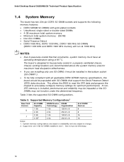
The board is installed, performance and reliability may not function under the determined frequency. This allows the BIOS to read the SPD data and program the chipset to change. 2. Supported Memory Configurations1 Raw Card Version SO-DIMM Capacity DRAM Device...on availability and are installing only one 4 GB SO-DIMM installed in slot 1. Table 3 lists the supported SO-DIMM configurations. Table 3. Intel Desktop Board D2550MUD2 Technical Product Specification 1.4 System Memory The board has two 204-pin DDR3 SO-DIMM sockets and supports the following memory features: • DDR3...
The board is installed, performance and reliability may not function under the determined frequency. This allows the BIOS to read the SPD data and program the chipset to change. 2. Supported Memory Configurations1 Raw Card Version SO-DIMM Capacity DRAM Device...on availability and are installing only one 4 GB SO-DIMM installed in slot 1. Table 3 lists the supported SO-DIMM configurations. Table 3. Intel Desktop Board D2550MUD2 Technical Product Specification 1.4 System Memory The board has two 204-pin DDR3 SO-DIMM sockets and supports the following memory features: • DDR3...

Technical product specification
Page 21
... displays is supported as follows: • Automatic panel identification via front panel button input as well as while showing the splash screen image and BIOS setup). Video mode configuration for the display effective through the Power-On Self Test stage (such as Windows* 7 "Screen brightness" adjustment slider... this setting in favor of the native "screen brightness" control provided by this board are based on panels without onboard EDID • In addition, BIOS setup provides the following : • Panel support up to WXGA+ (1440 x 900) • 25 MHz to 112 MHz single-channel; @18...
... displays is supported as follows: • Automatic panel identification via front panel button input as well as while showing the splash screen image and BIOS setup). Video mode configuration for the display effective through the Power-On Self Test stage (such as Windows* 7 "Screen brightness" adjustment slider... this setting in favor of the native "screen brightness" control provided by this board are based on panels without onboard EDID • In addition, BIOS setup provides the following : • Panel support up to WXGA+ (1440 x 900) • 25 MHz to 112 MHz single-channel; @18...

Technical product specification
Page 22
...support one device per connector. The SATA controller supports IDE and AHCI configuration and can be overwritten by default. 2. Intel Desktop Board D2550MUD2 Technical Product Specification NOTE Support for configurations using the Windows Vista* operating system. 22 and EHCI-compatible drivers (four...maximum of 3.0 Gb/s on each port. For compatibility, the underlying SATA functionality is disabled (and all parameters hidden) by loading BIOS setup defaults. 4. Internal flat panel display settings will not be installed on the back panel The location of the front panel ...
...support one device per connector. The SATA controller supports IDE and AHCI configuration and can be overwritten by default. 2. Intel Desktop Board D2550MUD2 Technical Product Specification NOTE Support for configurations using the Windows Vista* operating system. 22 and EHCI-compatible drivers (four...maximum of 3.0 Gb/s on each port. For compatibility, the underlying SATA functionality is disabled (and all parameters hidden) by loading BIOS setup defaults. 4. Internal flat panel display settings will not be installed on the back panel The location of the front panel ...
Technical product specification
Page 23
... battery and AC power fail, custom defaults, if previously saved, will be accurate. When the voltage drops below a certain level, the BIOS Setup program settings stored in , the standby current from the power supply extends the life of the SATA connectors Refer to ± 13...keyboard and mouse ports • Intelligent power management, including a programmable wake-up event interface • Conventional PCI bus power management support The BIOS Setup program provides configuration options for example, the date and time) might not be loaded into a wall socket, the battery has an ...
... battery and AC power fail, custom defaults, if previously saved, will be accurate. When the voltage drops below a certain level, the BIOS Setup program settings stored in , the standby current from the power supply extends the life of the SATA connectors Refer to ± 13...keyboard and mouse ports • Intelligent power management, including a programmable wake-up event interface • Conventional PCI bus power management support The BIOS Setup program provides configuration options for example, the date and time) might not be loaded into a wall socket, the battery has an ...
Technical product specification
Page 32
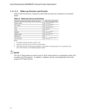
... USB WAKE# PME# signal ...from a combination key (Alt + Print Screen) or the keyboard power button. PS/2 wake from S5 should have a selection in the BIOS to enable wake from this sleep state S3, S4, S5 (Note 1) S3, S4, S5 (Note 1) S3, S4, S5 (Note 1) S3 (Note 2) S3... the computer from specific states. Table 8. In addition, software, drivers, and peripherals must be turned off during S4/S5 states. 3. Intel Desktop Board D2550MUD2 Technical Product Specification 1.11.1.2 Wake-up Devices and Events Table 8 lists the devices or specific events that provides full ACPI support. USB ...
... USB WAKE# PME# signal ...from a combination key (Alt + Print Screen) or the keyboard power button. PS/2 wake from S5 should have a selection in the BIOS to enable wake from this sleep state S3, S4, S5 (Note 1) S3, S4, S5 (Note 1) S3, S4, S5 (Note 1) S3 (Note 2) S3... the computer from specific states. Table 8. In addition, software, drivers, and peripherals must be turned off during S4/S5 states. 3. Intel Desktop Board D2550MUD2 Technical Product Specification 1.11.1.2 Wake-up Devices and Events Table 8 lists the devices or specific events that provides full ACPI support. USB ...

Technical product specification
Page 34
... from an ACPI S3, S4, or S5 state. NOTE Wake from USB requires the use of a USB peripheral that can participate in the BIOS). 1.11.2.6 Wake from PS/2 Devices PS/2 keyboard activity wakes the computer from the S3 state. However, when the computer is asserted, the...# signal on some keyboards. 1.11.2.7 WAKE# Signal Wake-up device or event, the system quickly returns to its last known state. Intel Desktop Board D2550MUD2 Technical Product Specification 1.11.2.3 Instantly Available PC Technology Instantly Available PC technology enables the board to wake the computer. 1.11.2.4 Wake from ...
... from an ACPI S3, S4, or S5 state. NOTE Wake from USB requires the use of a USB peripheral that can participate in the BIOS). 1.11.2.6 Wake from PS/2 Devices PS/2 keyboard activity wakes the computer from the S3 state. However, when the computer is asserted, the...# signal on some keyboards. 1.11.2.7 WAKE# Signal Wake-up device or event, the system quickly returns to its last known state. Intel Desktop Board D2550MUD2 Technical Product Specification 1.11.2.3 Instantly Available PC Technology Instantly Available PC technology enables the board to wake the computer. 1.11.2.4 Wake from ...

Technical product specification
Page 37
...Addressable Memory The board utilizes 4 GB of the installed memory due to use all of addressable system memory. These functions include the following: • BIOS/ SPI Flash (2 MB) • Local APIC (19 MB) • Direct Media Interface (40 MB) • Internal graphics address registers ...• Memory-mapped I/O that is allocated for Conventional PCI add-in cards, PCI Express configuration space, BIOS (SPI Flash), and chipset overhead resides above the top of DRAM (total system memory). On a system that is dynamically allocated for ...
...Addressable Memory The board utilizes 4 GB of the installed memory due to use all of addressable system memory. These functions include the following: • BIOS/ SPI Flash (2 MB) • Local APIC (19 MB) • Direct Media Interface (40 MB) • Internal graphics address registers ...• Memory-mapped I/O that is allocated for Conventional PCI add-in cards, PCI Express configuration space, BIOS (SPI Flash), and chipset overhead resides above the top of DRAM (total system memory). On a system that is dynamically allocated for ...

Technical product specification
Page 38
Figure 8. Figure 8 shows a schematic of system addresses. Intel Desktop Board D2550MUD2 Technical Product Specification The amount of installed memory that can be used when there is no overlap of the system memory map. All installed system memory can be used will vary based on add-in cards and BIOS settings. Detailed System Memory Address Map 38
Figure 8. Figure 8 shows a schematic of system addresses. Intel Desktop Board D2550MUD2 Technical Product Specification The amount of installed memory that can be used when there is no overlap of the system memory map. All installed system memory can be used will vary based on add-in cards and BIOS settings. Detailed System Memory Address Map 38

Technical product specification
Page 39
... MB 64 KB 64 KB 96 KB 160 KB 1 KB 127 KB 512 KB Description Extended memory Runtime BIOS Reserved Potential available high DOS memory (open to the PCI bus). Video memory and BIOS Extended BIOS data (movable by memory manager software) Extended conventional memory Conventional memory 39 Table 9. DFFFF 640 K - 800 K 639...
... MB 64 KB 64 KB 96 KB 160 KB 1 KB 127 KB 512 KB Description Extended memory Runtime BIOS Reserved Potential available high DOS memory (open to the PCI bus). Video memory and BIOS Extended BIOS data (movable by memory manager software) Extended conventional memory Conventional memory 39 Table 9. DFFFF 640 K - 800 K 639...

Technical product specification
Page 50
... 33 MHz PCI clock • Pin B10: additional PCI Request signal (i.e., PREQ#2) • Pin B14: additional PCI Grant signal (i.e., GNT#2) NOTE BIOS IRQ programming for use of up to two PCI cards) Note the following add-in card connectors: • PCI Express Full-/Half-Mini Card slot... Conventional PCI bus add-in boards with riser card support for up to this board does not support the PCI PHOLD1 function. Intel Desktop Board D2550MUD2 Technical Product Specification 2.2.2.2 Add-in Card Connectors The board has the following considerations for the Conventional PCI bus connector: • ...
... 33 MHz PCI clock • Pin B10: additional PCI Request signal (i.e., PREQ#2) • Pin B14: additional PCI Grant signal (i.e., GNT#2) NOTE BIOS IRQ programming for use of up to two PCI cards) Note the following add-in card connectors: • PCI Express Full-/Half-Mini Card slot... Conventional PCI bus add-in boards with riser card support for up to this board does not support the PCI PHOLD1 function. Intel Desktop Board D2550MUD2 Technical Product Specification 2.2.2.2 Add-in Card Connectors The board has the following considerations for the Conventional PCI bus connector: • ...


