
Product Specification
Page 5
... Layout 12 1.2 Online Support ...14 1.3 Processor ...14 1.4 System Memory ...15 1.5 ATI Radeon* Xpress 200 Chipset 16 1.5.1 Graphics Subsystem 16 1.5.2 Firmware Hub (FWH 16 1.5.3 USB ...16 1.5.4 IDE Support 17 1.5.5 Real-Time Clock, CMOS SRAM, and Battery 18 1.6 PCI Express* Connectors 18 1.7 Legacy I/O Controller 19 1.7.1 Serial Port...19 1.7.2 Parallel Port... PCI Configuration Space Map 35 2.6 PCI Conventional Interrupt Routing Map 35 2.7 Connectors...36 2.7.1 Back Panel Connectors 37 2.7.2 Component-side Connectors 38 2.7.3 Front Panel USB Connectors 44 2.8 Jumper Block ...45 v
... Layout 12 1.2 Online Support ...14 1.3 Processor ...14 1.4 System Memory ...15 1.5 ATI Radeon* Xpress 200 Chipset 16 1.5.1 Graphics Subsystem 16 1.5.2 Firmware Hub (FWH 16 1.5.3 USB ...16 1.5.4 IDE Support 17 1.5.5 Real-Time Clock, CMOS SRAM, and Battery 18 1.6 PCI Express* Connectors 18 1.7 Legacy I/O Controller 19 1.7.1 Serial Port...19 1.7.2 Parallel Port... PCI Configuration Space Map 35 2.6 PCI Conventional Interrupt Routing Map 35 2.7 Connectors...36 2.7.1 Back Panel Connectors 37 2.7.2 Component-side Connectors 38 2.7.3 Front Panel USB Connectors 44 2.8 Jumper Block ...45 v
Product Specification
Page 6
Intel Desktop Board D101GGC Technical Product Specification 2.9 Mechanical Considerations 46 2.9.1 Form Factor 46 2.9.2 I/O Shield...47 2.10 Electrical Considerations 48 2.10.1 DC Loading...48 2.10.2 Add-in Board... 3.1 Introduction ...61 3.2 BIOS Flash Memory Organization 62 3.3 Resource Configuration 62 3.3.1 PCI Autoconfiguration 62 3.3.2 PCI IDE Support 62 3.4 System Management BIOS (SMBIOS 63 3.5 Legacy USB Support...63 3.6 BIOS Updates ...64 3.6.1 Language Support 64 3.6.2 Custom Splash Screen 64 3.7 Boot Options ...65 3.7.1 CD-ROM Boot 65 3.7.2 Network Boot 65 3.7.3 Booting ...
Intel Desktop Board D101GGC Technical Product Specification 2.9 Mechanical Considerations 46 2.9.1 Form Factor 46 2.9.2 I/O Shield...47 2.10 Electrical Considerations 48 2.10.1 DC Loading...48 2.10.2 Add-in Board... 3.1 Introduction ...61 3.2 BIOS Flash Memory Organization 62 3.3 Resource Configuration 62 3.3.1 PCI Autoconfiguration 62 3.3.2 PCI IDE Support 62 3.4 System Management BIOS (SMBIOS 63 3.5 Legacy USB Support...63 3.6 BIOS Updates ...64 3.6.1 Language Support 64 3.6.2 Custom Splash Screen 64 3.7 Boot Options ...65 3.7.1 CD-ROM Boot 65 3.7.2 Network Boot 65 3.7.3 Booting ...

Product Specification
Page 7
... Fan Connectors 40 22. Front Panel Connector 42 26. Contents Figures 1. Component-side Connectors 38 8. Localized High Temperature Zones 51 Tables 1. States for Front Panel USB Connectors 44 10. DMA Channels ...32 11. Board Components ...12 3. Board Dimensions...46 12. Processor Heatsink for High Definition Audio Subsystem...... 21 4. ATX12V Power Connector...
... Fan Connectors 40 22. Front Panel Connector 42 26. Contents Figures 1. Component-side Connectors 38 8. Localized High Temperature Zones 51 Tables 1. States for Front Panel USB Connectors 44 10. DMA Channels ...32 11. Board Components ...12 3. Board Dimensions...46 12. Processor Heatsink for High Definition Audio Subsystem...... 21 4. ATX12V Power Connector...
Product Specification
Page 10
Intel Desktop Board D101GGC Technical Product Specification 1.1 Overview 1.1.1 Feature Summary Table 1 summarizes the major features of range thermal values • Three fan connectors • Three fan sense inputs...range power supply voltages • Thermal sense to Section 1.2, page 14 10 Table 1. Feature Summary Form Factor Processor Memory Chipset Video Audio Legacy I/O Control USB Peripheral Interfaces LAN Support BIOS Expansion Capabilities Instantly Available PC Technology Hardware Monitor Subsystem (controlled by SMSC SCH5017 I/O controller) microATX (9.60 inches by 8.60 ...
Intel Desktop Board D101GGC Technical Product Specification 1.1 Overview 1.1.1 Feature Summary Table 1 summarizes the major features of range thermal values • Three fan connectors • Three fan sense inputs...range power supply voltages • Thermal sense to Section 1.2, page 14 10 Table 1. Feature Summary Form Factor Processor Memory Chipset Video Audio Legacy I/O Control USB Peripheral Interfaces LAN Support BIOS Expansion Capabilities Instantly Available PC Technology Hardware Monitor Subsystem (controlled by SMSC SCH5017 I/O controller) microATX (9.60 inches by 8.60 ...
Product Specification
Page 11
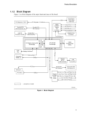
... Express x1 Slot 1 PCI Express x1 Interface Parallel ATA IDE Connectors (2) Parallel ATA IDE Interface LGA775 Processor Socket System Bus (800/533 MHz) USB Back Panel/ Front Panel USB Ports SMSC SCH5017 Legacy I/O Controller LPC Bus Serial Port Parallel Port PS/2 Mouse PS/2 Keyboard Diskette Drive Connector PCI Express x4 Interface High...
... Express x1 Slot 1 PCI Express x1 Interface Parallel ATA IDE Connectors (2) Parallel ATA IDE Interface LGA775 Processor Socket System Bus (800/533 MHz) USB Back Panel/ Front Panel USB Ports SMSC SCH5017 Legacy I/O Controller LPC Bus Serial Port Parallel Port PS/2 Mouse PS/2 Keyboard Diskette Drive Connector PCI Express x4 Interface High...

Product Specification
Page 13
... power LED connector U Front panel connector V 4 Mbit Firmware Hub (FWH) W IXP 450 Southbridge X Speaker Y Front panel USB connector Z BIOS Setup configuration jumper block AA PCI Conventional bus add-in card connectors [2] BB Front panel USB connector CC PCI Express x1 bus add-in card connector DD Standby power indicator LED Product Description...
... power LED connector U Front panel connector V 4 Mbit Firmware Hub (FWH) W IXP 450 Southbridge X Speaker Y Front panel USB connector Z BIOS Setup configuration jumper block AA PCI Conventional bus add-in card connectors [2] BB Front panel USB connector CC PCI Express x1 bus add-in card connector DD Standby power indicator LED Product Description...
Product Specification
Page 16
... Hub (FWH) The Firmware Hub provides the nonvolatile storage of the AwardBIOS for Intel. 1.5.3 USB The board supports up to Figure 6, page 37 Figure 7, page 38 16 The IXP 450 Southbridge provides the USB controller for the system bus, the memory bus, and the PCI Express bus...Use shielded cable that have an unshielded cable attached to a USB port may not meet FCC Class B requirements, even if no device is a centralized controller for all ports. and EHCI-compatible drivers. Intel Desktop Board D101GGC Technical Product Specification 1.5 ATI Radeon* Xpress 200 Chipset The ATI...
... Hub (FWH) The Firmware Hub provides the nonvolatile storage of the AwardBIOS for Intel. 1.5.3 USB The board supports up to Figure 6, page 37 Figure 7, page 38 16 The IXP 450 Southbridge provides the USB controller for the system bus, the memory bus, and the PCI Express bus...Use shielded cable that have an unshielded cable attached to a USB port may not meet FCC Class B requirements, even if no device is a centralized controller for all ports. and EHCI-compatible drivers. Intel Desktop Board D101GGC Technical Product Specification 1.5 ATI Radeon* Xpress 200 Chipset The ATI...

Product Specification
Page 23
... feature that attaches to the chassis intrusion connector. Product Description 1.10 Hardware Management Subsystem The hardware management features enable the board to be implemented using Intel® Desktop Utilities, LANDesk* software, or thirdparty software. The SMSC SCH5017 I /O controller include: • Internal ambient temperature sensor • Two remote thermal ... -loop fan control, for all three fans, that can adjust the fan speed or switch the fans on Ring ⎯ Wake from USB ⎯ Wake from PS/2 devices ⎯ Power Management Event signal (PME#) wake-up support 23
... feature that attaches to the chassis intrusion connector. Product Description 1.10 Hardware Management Subsystem The hardware management features enable the board to be implemented using Intel® Desktop Utilities, LANDesk* software, or thirdparty software. The SMSC SCH5017 I /O controller include: • Internal ambient temperature sensor • Two remote thermal ... -loop fan control, for all three fans, that can adjust the fan speed or switch the fans on Ring ⎯ Wake from USB ⎯ Wake from PS/2 devices ⎯ Power Management Event signal (PME#) wake-up support 23
Product Specification
Page 25
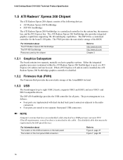
...-in boards and peripherals powered by the system chassis' power supply. 2. LAN Modem (back panel Serial Port A) PME# signal Power switch PS/2 devices RTC alarm USB WAKE# signal ...from this option to Power On will enable a wake-up event from LAN in the BIOS Setup program. Power States and Targeted System...
...-in boards and peripherals powered by the system chassis' power supply. 2. LAN Modem (back panel Serial Port A) PME# signal Power switch PS/2 devices RTC alarm USB WAKE# signal ...from this option to Power On will enable a wake-up event from LAN in the BIOS Setup program. Power States and Targeted System...
Product Specification
Page 26
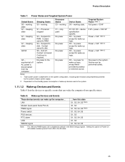
Intel Desktop Board D101GGC Technical Product Specification NOTE The use of standby current required depends ... and Instantly Available PC technology require power from the +5 V standby line. Resume on Ring and Wake from USB technologies from an ACPI state requires an operating system that the power supply provides adequate +5 V standby current if... LAN wake capabilities and Instantly Available PC technology features are used depends on Ring • Wake from USB • Wake from PS/2 keyboard • PME# signal wake-up support • WAKE# signal wake-up events...
Intel Desktop Board D101GGC Technical Product Specification NOTE The use of standby current required depends ... and Instantly Available PC technology require power from the +5 V standby line. Resume on Ring and Wake from USB technologies from an ACPI state requires an operating system that the power supply provides adequate +5 V standby current if... LAN wake capabilities and Instantly Available PC technology features are used depends on Ring • Wake from USB • Wake from PS/2 keyboard • PME# signal wake-up support • WAKE# signal wake-up events...
Product Specification
Page 28
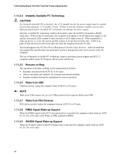
Intel Desktop Board D101GGC Technical Product Specification 1.11.2.4 Instantly Available PC Technology CAUTION For Instantly Available PC technology, the +5 V standby line for the power supply must be capable of ... the WAKE# signal on PME enabled in the S3 sleep-state, the computer will appear to be used to -RAM) sleep-state. NOTE Wake from USB requires the use of Instantly Available PC technology requires operating system support and PCI 2.2 compliant add-in cards, PCI Express add-in power management and...
Intel Desktop Board D101GGC Technical Product Specification 1.11.2.4 Instantly Available PC Technology CAUTION For Instantly Available PC technology, the +5 V standby line for the power supply must be capable of ... the WAKE# signal on PME enabled in the S3 sleep-state, the computer will appear to be used to -RAM) sleep-state. NOTE Wake from USB requires the use of Instantly Available PC technology requires operating system support and PCI 2.2 compliant add-in cards, PCI Express add-in power management and...
Product Specification
Page 35
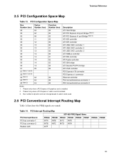
... Bridge ATI PCI Express x16 port Bridge (Note 1) ATI PCI Express x1 port Bridge (Note 2) ATI IDE controller ATI IDE controller ATI USB OHCI controller 1 ATI USB OHCI controller 2 ATI USB OHCI controller 3 ATI SMBus controller ATI IDE controller ATI Azalia controller ATI ISA bridge ATI Decode PCI/PCI bridge ATI VGA controller...
... Bridge ATI PCI Express x16 port Bridge (Note 1) ATI PCI Express x1 port Bridge (Note 2) ATI IDE controller ATI IDE controller ATI USB OHCI controller 1 ATI USB OHCI controller 2 ATI USB OHCI controller 3 ATI SMBus controller ATI IDE controller ATI Azalia controller ATI ISA bridge ATI Decode PCI/PCI bridge ATI VGA controller...
Product Specification
Page 36
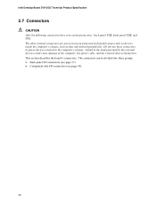
Intel Desktop Board D101GGC Technical Product Specification 2.7 Connectors CAUTION Only the following connectors have overcurrent protection: back panel USB, front panel USB, and PS/2. This section describes the board's connectors. The other internal connectors are not overcurrent protected and should connect only to the computer, the power ...
Intel Desktop Board D101GGC Technical Product Specification 2.7 Connectors CAUTION Only the following connectors have overcurrent protection: back panel USB, front panel USB, and PS/2. This section describes the board's connectors. The other internal connectors are not overcurrent protected and should connect only to the computer, the power ...

Product Specification
Page 37
... Connectors Shown in Figure 6 Item/callout from Figure 6 Description A PS/2 mouse port (Green) B PS/2 keyboard port (Purple) C Parallel port (Burgundy) D Serial port A (Teal) E VGA port F USB ports [4] G LAN H Line in or Rear Left/Right Out I D E F Figure 6. Back Panel Connectors HJ OM18248 Table 15.
... Connectors Shown in Figure 6 Item/callout from Figure 6 Description A PS/2 mouse port (Green) B PS/2 keyboard port (Purple) C Parallel port (Burgundy) D Serial port A (Teal) E VGA port F USB ports [4] G LAN H Line in or Rear Left/Right Out I D E F Figure 6. Back Panel Connectors HJ OM18248 Table 15.

Product Specification
Page 44
Intel Desktop Board D101GGC Technical Product Specification NOTE The colors listed in Table 26 and Table 27 are product- or customer-specific. 2.7.2.4.4 Power Switch Connector [Red] Pins 6 and 8 [Red] can be connected to the USB 2.0 specification for Front Panel USB Connectors 44 Connection Diagram for... are suggested colors only. Power (+5 V DC) One D− USB Port D+ 1 2 3 4 5 6 Power (+5 V DC) D− One USB D+ Port Ground 7 8 Ground Key (no pin) 10 No Connect OM15963 Figure 9. speed USB devices. The switch must pull the SW_ON# pin to ground for at...
Intel Desktop Board D101GGC Technical Product Specification NOTE The colors listed in Table 26 and Table 27 are product- or customer-specific. 2.7.2.4.4 Power Switch Connector [Red] Pins 6 and 8 [Red] can be connected to the USB 2.0 specification for Front Panel USB Connectors 44 Connection Diagram for... are suggested colors only. Power (+5 V DC) One D− USB Port D+ 1 2 3 4 5 6 Power (+5 V DC) D− One USB D+ Port Ground 7 8 Ground Key (no pin) 10 No Connect OM15963 Figure 9. speed USB devices. The switch must pull the SW_ON# pin to ground for at...
Product Specification
Page 48
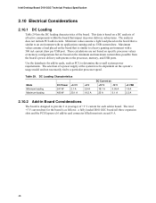
... A +5 V 2.9 A 19.3 A DC Current at the system level is designed to determine the overall system power requirements. Intel Desktop Board D101GGC Technical Product Specification 2.10 Electrical Considerations 2.10.1 DC Loading Table 29 lists the DC loading characteristics of all three expansion slots and....2 Add-in Board Considerations The board is dependent on the system's usage model and not necessarily tied to the processor, memory, and USB ports. These calculations are not based on specific processor values or memory configurations but are based on a DC analysis of the board. ...
... A +5 V 2.9 A 19.3 A DC Current at the system level is designed to determine the overall system power requirements. Intel Desktop Board D101GGC Technical Product Specification 2.10 Electrical Considerations 2.10.1 DC Loading Table 29 lists the DC loading characteristics of all three expansion slots and....2 Add-in Board Considerations The board is dependent on the system's usage model and not necessarily tied to the processor, memory, and USB ports. These calculations are not based on specific processor values or memory configurations but are based on a DC analysis of the board. ...
Product Specification
Page 61
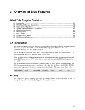
... What This Chapter Contains 3.1 Introduction ...61 3.2 BIOS Flash Memory Organization 62 3.3 Resource Configuration 62 3.4 System Management BIOS (SMBIOS 63 3.5 Legacy USB Support...63 3.6 BIOS Updates ...64 3.7 Boot Options ...65 3.8 Adjusting Boot Speed 66 3.9 BIOS Security Features 67 3.1 Introduction The boards use an... Intel BIOS that is shown below. The BIOS Setup program can be used to view and change the BIOS settings for the computer. 3 ...
... What This Chapter Contains 3.1 Introduction ...61 3.2 BIOS Flash Memory Organization 62 3.3 Resource Configuration 62 3.4 System Management BIOS (SMBIOS 63 3.5 Legacy USB Support...63 3.6 BIOS Updates ...64 3.7 Boot Options ...65 3.8 Adjusting Boot Speed 66 3.9 BIOS Security Features 67 3.1 Introduction The boards use an... Intel BIOS that is shown below. The BIOS Setup program can be used to view and change the BIOS settings for the computer. 3 ...
Product Specification
Page 63
... about the computing system and its components. For example, do not connect an ATA hard drive as third-party management software to use a USB keyboard to the computer, legacy support is a Desktop Management Interface (DMI) compliant method for accessing this support, an SMBIOS service-level application ...running on a non-Plug and Play operating system can obtain the SMBIOS information. 3.5 Legacy USB Support Legacy USB support enables USB devices to be used to access the BIOS Setup program, and to use SMBIOS. The MIF database defines the data and ...
... about the computing system and its components. For example, do not connect an ATA hard drive as third-party management software to use a USB keyboard to the computer, legacy support is a Desktop Management Interface (DMI) compliant method for accessing this support, an SMBIOS service-level application ...running on a non-Plug and Play operating system can obtain the SMBIOS information. 3.5 Legacy USB Support Legacy USB support enables USB devices to be used to access the BIOS Setup program, and to use SMBIOS. The MIF database defines the data and ...
Product Specification
Page 64
... the system. This splash screen can be used to create a custom splash screen. Intel Desktop Board D101GGC Technical Product Specification 5. While the operating system is no longer used to prevent accidentally ...installing an incompatible BIOS. To install an operating system that supports USB, follow the operating system's installation instructions. 3.6 BIOS Updates The BIOS can be updated from a file on the Intel World Wide Web site. For information about The Intel...
... the system. This splash screen can be used to create a custom splash screen. Intel Desktop Board D101GGC Technical Product Specification 5. While the operating system is no longer used to prevent accidentally ...installing an incompatible BIOS. To install an operating system that supports USB, follow the operating system's installation instructions. 3.6 BIOS Updates The BIOS can be updated from a file on the Intel World Wide Web site. For information about The Intel...

Product Specification
Page 72
...entering AWDFLASH.EXE from FDD (optional feature) 1. continued 72 Initialize Init_Onbaord_AUDIO switch. Assign resources to every ISA Plug and Play device. Intel Desktop Board D101GGC Technical Product Specification Table 42. Port 80h POST Codes (continued) POST Code 50h 52h 55h 57h 59h 5Bh 5Dh 60h 65h 67h 69h... 6Bh 6Dh 6Fh 73h 75h 77h 7Ah 7Fh Description of POST Operation Initialize USB Test all memory (clear all ISA Plug and Play ...
...entering AWDFLASH.EXE from FDD (optional feature) 1. continued 72 Initialize Init_Onbaord_AUDIO switch. Assign resources to every ISA Plug and Play device. Intel Desktop Board D101GGC Technical Product Specification Table 42. Port 80h POST Codes (continued) POST Code 50h 52h 55h 57h 59h 5Bh 5Dh 60h 65h 67h 69h... 6Bh 6Dh 6Fh 73h 75h 77h 7Ah 7Fh Description of POST Operation Initialize USB Test all memory (clear all ISA Plug and Play ...

