
Product Specification
Page 6
Intel Desktop Board D101GGC Technical Product Specification 2.9 Mechanical Considerations 46 2.9.1 Form Factor 46 2.9.2 I/O Shield...47 2.10 Electrical Considerations 48 2.10.1 DC Loading...48 2.10.2 Add-in Board Considerations 48 2.10.3 Fan Connector Current Capability 49 2.10.4 ...(Board Level 60 3 Overview of BIOS Features 3.1 Introduction ...61 3.2 BIOS Flash Memory Organization 62 3.3 Resource Configuration 62 3.3.1 PCI Autoconfiguration 62 3.3.2 PCI IDE Support 62 3.4 System Management BIOS (SMBIOS 63 3.5 Legacy USB Support...63 3.6 BIOS Updates ...64 3.6.1 Language Support 64 ...
Intel Desktop Board D101GGC Technical Product Specification 2.9 Mechanical Considerations 46 2.9.1 Form Factor 46 2.9.2 I/O Shield...47 2.10 Electrical Considerations 48 2.10.1 DC Loading...48 2.10.2 Add-in Board Considerations 48 2.10.3 Fan Connector Current Capability 49 2.10.4 ...(Board Level 60 3 Overview of BIOS Features 3.1 Introduction ...61 3.2 BIOS Flash Memory Organization 62 3.3 Resource Configuration 62 3.3.1 PCI Autoconfiguration 62 3.3.2 PCI IDE Support 62 3.4 System Management BIOS (SMBIOS 63 3.5 Legacy USB Support...63 3.6 BIOS Updates ...64 3.6.1 Language Support 64 ...
Product Specification
Page 10
...AwardBIOS* for Intel® resident in the 4 Mbit FWH • Two PCI Conventional* bus connectors • One PCI Express* x1 bus add-in card connector • One PCI Express x16 bus add-in card connector • Support for PCI Local Bus Specification Revision 2.2 • Support for PCI Express Revision... RAM support • Wake on PCI, RS-232, front panel, PS/2 devices, and USB ports • Voltage sense to detect out of range power supply voltages • Thermal sense to detect out of the board. Intel Desktop Board D101GGC Technical Product Specification 1.1 Overview 1.1.1 Feature...
...AwardBIOS* for Intel® resident in the 4 Mbit FWH • Two PCI Conventional* bus connectors • One PCI Express* x1 bus add-in card connector • One PCI Express x16 bus add-in card connector • Support for PCI Local Bus Specification Revision 2.2 • Support for PCI Express Revision... RAM support • Wake on PCI, RS-232, front panel, PS/2 devices, and USB ports • Voltage sense to detect out of range power supply voltages • Thermal sense to detect out of the board. Intel Desktop Board D101GGC Technical Product Specification 1.1 Overview 1.1.1 Feature...

Product Specification
Page 13
Board Components Shown in Figure 2 Item/callout from Figure 2 Description A Front panel audio connector B Audio codec C PCI Express x16 add-in card connector D Ethernet device E Back panel connectors F +12V power connector (ATX12V) G Rear chassis fan connector H ... Hub (FWH) W IXP 450 Southbridge X Speaker Y Front panel USB connector Z BIOS Setup configuration jumper block AA PCI Conventional bus add-in card connectors [2] BB Front panel USB connector CC PCI Express x1 bus add-in card connector DD Standby power indicator LED Product Description 13 Table 2.
Board Components Shown in Figure 2 Item/callout from Figure 2 Description A Front panel audio connector B Audio codec C PCI Express x16 add-in card connector D Ethernet device E Back panel connectors F +12V power connector (ATX12V) G Rear chassis fan connector H ... Hub (FWH) W IXP 450 Southbridge X Speaker Y Front panel USB connector Z BIOS Setup configuration jumper block AA PCI Conventional bus add-in card connectors [2] BB Front panel USB connector CC PCI Express x1 bus add-in card connector DD Standby power indicator LED Product Description 13 Table 2.
Product Specification
Page 16
... The location of the front panel USB connectors Refer to eight USB 2.0 ports, supports UHCI and EHCI, and uses UHCI- Intel Desktop Board D101GGC Technical Product Specification 1.5 ATI Radeon* Xpress 200 Chipset The ATI Radeon Xpress 200 chipset consists of the following devices: •... the board's I/O paths. Either the integrated graphics processor (contained within the ATI Radeon Xpress 200 Northbridge) is used, or a PCI Express x16 add-in card is installed, the ATI Radeon Xpress 200 Northbridge graphics controller is as follows: • Four ports are implemented with dual...
... The location of the front panel USB connectors Refer to eight USB 2.0 ports, supports UHCI and EHCI, and uses UHCI- Intel Desktop Board D101GGC Technical Product Specification 1.5 ATI Radeon* Xpress 200 Chipset The ATI Radeon Xpress 200 chipset consists of the following devices: •... the board's I/O paths. Either the integrated graphics processor (contained within the ATI Radeon Xpress 200 Northbridge) is used, or a PCI Express x16 add-in card is installed, the ATI Radeon Xpress 200 Northbridge graphics controller is as follows: • Four ports are implemented with dual...
Product Specification
Page 28
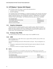
... state. NOTE Wake from USB requires the use of Instantly Available PC technology requires operating system support and PCI 2.2 compliant add-in cards, PCI Express add-in boards that can wake the computer from the S3 state. Instantly Available PC technology enables the board... Instantly Available PC technology can damage the power supply. Add-in cards, and drivers. 1.11.2.5 Resume on Ring The operation of providing adequate +5 V standby current. Failure to -RAM) sleep-state. Intel Desktop Board D101GGC Technical Product Specification 1.11.2.4 Instantly Available PC Technology CAUTION...
... state. NOTE Wake from USB requires the use of Instantly Available PC technology requires operating system support and PCI 2.2 compliant add-in cards, PCI Express add-in boards that can wake the computer from the S3 state. Instantly Available PC technology enables the board... Instantly Available PC technology can damage the power supply. Add-in cards, and drivers. 1.11.2.5 Resume on Ring The operation of providing adequate +5 V standby current. Failure to -RAM) sleep-state. Intel Desktop Board D101GGC Technical Product Specification 1.11.2.4 Instantly Available PC Technology CAUTION...
Product Specification
Page 35
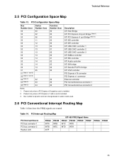
Present only when a PCI Express x1 add-in cards used. 2.6 PCI Conventional Interrupt Routing Map Table 14 lists how the PIRQ signals are routed. PCI Interrupt Routing Map PCI Interrupt Source PCI bus connector 1 PCI bus connector 2 Realtek LAN PIRQA INTA INTB INTF PIRQB INTB INTC IXP 450 PIRQ Signal Name PIRQC ...PIRQE PIRQF INTC INTD INTD INTA PIRQG PIRQH 35 Bus number is dynamic and can change based on add-in card is installed. 2. Technical Reference 2.5 PCI Configuration Space Map Table 13. PCI Configuration Space Map Bus Number (hex) 00 00 00 00 00 00 00 00 00 00 ...
Present only when a PCI Express x1 add-in cards used. 2.6 PCI Conventional Interrupt Routing Map Table 14 lists how the PIRQ signals are routed. PCI Interrupt Routing Map PCI Interrupt Source PCI bus connector 1 PCI bus connector 2 Realtek LAN PIRQA INTA INTB INTF PIRQB INTB INTC IXP 450 PIRQ Signal Name PIRQC ...PIRQE PIRQF INTC INTD INTD INTA PIRQG PIRQH 35 Bus number is dynamic and can change based on add-in card is installed. 2. Technical Reference 2.5 PCI Configuration Space Map Table 13. PCI Configuration Space Map Bus Number (hex) 00 00 00 00 00 00 00 00 00 00 ...

Product Specification
Page 42
... Connector This section describes the functions of the front panel connector. Table 25. PCI Conventional bus add-in boards with SMBus support can access sensor data and other information residing on the board. Intel Desktop Board D101GGC Technical Product Specification 2.7.2.2 Add-in Card Connectors The board has the following considerations for the front panel connector...
... Connector This section describes the functions of the front panel connector. Table 25. PCI Conventional bus add-in boards with SMBus support can access sensor data and other information residing on the board. Intel Desktop Board D101GGC Technical Product Specification 2.7.2.2 Add-in Card Connectors The board has the following considerations for the front panel connector...
Product Specification
Page 48
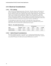
... system power requirements. Use the datasheets for add-in cards, such as follows: a fully loaded D101GGC board (all active components within the board that impact its power delivery subsystems. The analysis does not include PCI add-in card connector filled) must not exceed...2.9 A 19.3 A DC Current at the system level is dependent on the board that is similar to provide 2 A (average) of the board. Intel Desktop Board D101GGC Technical Product Specification 2.10 Electrical Considerations 2.10.1 DC Loading Table 29 lists the DC loading characteristics of +5 V current for the board is as...
... system power requirements. Use the datasheets for add-in cards, such as follows: a fully loaded D101GGC board (all active components within the board that impact its power delivery subsystems. The analysis does not include PCI add-in card connector filled) must not exceed...2.9 A 19.3 A DC Current at the system level is dependent on the board that is similar to provide 2 A (average) of the board. Intel Desktop Board D101GGC Technical Product Specification 2.10 Electrical Considerations 2.10.1 DC Loading Table 29 lists the DC loading characteristics of +5 V current for the board is as...
Product Specification
Page 62
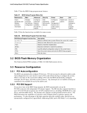
...The Firmware Hub (FWH) includes a 4 Mbit (512 KB) flash memory device. 3.3 Resource Configuration 3.3.1 PCI Autoconfiguration The BIOS can automatically configure PCI devices. Intel Desktop Board D101GGC Technical Product Specification Table 37 lists the BIOS Setup program menu features. Table 37. To take advantage of... each drive and configures them to be onboard or add-in cards. The BIOS ...
...The Firmware Hub (FWH) includes a 4 Mbit (512 KB) flash memory device. 3.3 Resource Configuration 3.3.1 PCI Autoconfiguration The BIOS can automatically configure PCI devices. Intel Desktop Board D101GGC Technical Product Specification Table 37 lists the BIOS Setup program menu features. Table 37. To take advantage of... each drive and configures them to be onboard or add-in cards. The BIOS ...
Product Specification
Page 70
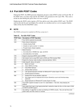
...Table 42. Test special keyboard controller for Winbond 977 series Super I /O chips. If test fails, keep beeping the speaker. Intel Desktop Board D101GGC Technical Product Specification 4.4 Port 80h POST Codes During the POST, the BIOS generates diagnostic progress codes (POST-codes) to load ...2. Auto-detect ports for override. Reset keyboard for determining the point where an error occurred. Displaying the POST-codes requires a PCI bus add-in CMOS circuitry. Program basic chipset registers Detect memory - Initialize 8042 self-test 1. Use walking 1's algorithm to E000 and ...
...Table 42. Test special keyboard controller for Winbond 977 series Super I /O chips. If test fails, keep beeping the speaker. Intel Desktop Board D101GGC Technical Product Specification 4.4 Port 80h POST Codes During the POST, the BIOS generates diagnostic progress codes (POST-codes) to load ...2. Auto-detect ports for override. Reset keyboard for determining the point where an error occurred. Displaying the POST-codes requires a PCI bus add-in CMOS circuitry. Program basic chipset registers Detect memory - Initialize 8042 self-test 1. Use walking 1's algorithm to E000 and ...
Intel Desktop Board D101GGC Product Guide English
Page 9
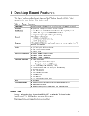
... • Wake on USB, PCI, PCI Express, PS/2, LAN, and front panel Related Links: For more information about desktop board D101GGC, including the Technical Product Specification (TPS), BIOS updates, and device drivers, go to 2 GB of Intel® Desktop Board D101GGC. Table 1. 1 Desktop Board ...200 Chipset • High Definition Audio interface • Realtek* codec Expansion Capabilities • Two PCI bus add-in card connectors • One PCI Express x16 connector • One PCI Express x1 connector Peripheral Interfaces • Eight USB 2.0 ports ⎯ Four ports routed to ...
... • Wake on USB, PCI, PCI Express, PS/2, LAN, and front panel Related Links: For more information about desktop board D101GGC, including the Technical Product Specification (TPS), BIOS updates, and device drivers, go to 2 GB of Intel® Desktop Board D101GGC. Table 1. 1 Desktop Board ...200 Chipset • High Definition Audio interface • Realtek* codec Expansion Capabilities • Two PCI bus add-in card connectors • One PCI Express x16 connector • One PCI Express x1 connector Peripheral Interfaces • Eight USB 2.0 ports ⎯ Four ports routed to ...
Intel Desktop Board D101GGC Product Guide English
Page 12
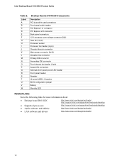
... M N O P Q R S T U V W Desktop Boards D101GGC Components Description PCI bus add-in card connectors Front panel audio header PCI Express* x1 connector PCI Express x16 connector Back panel connectors 12 V processor core voltage connector (2x2...D101GGC • Supported processors • Audio software and utilities • LAN software and drivers http://www.intel.com/design/motherbd http://support.intel.com/support/motherboards/desktop http://support.intel.com/support/motherboards/desktop http://www.intel.com/design/motherbd http://www.intel.com/design/motherbd 12 Intel Desktop Board D101GGC...
... M N O P Q R S T U V W Desktop Boards D101GGC Components Description PCI bus add-in card connectors Front panel audio header PCI Express* x1 connector PCI Express x16 connector Back panel connectors 12 V processor core voltage connector (2x2...D101GGC • Supported processors • Audio software and utilities • LAN software and drivers http://www.intel.com/design/motherbd http://support.intel.com/support/motherboards/desktop http://support.intel.com/support/motherboards/desktop http://www.intel.com/design/motherbd http://www.intel.com/design/motherbd 12 Intel Desktop Board D101GGC...
Intel Desktop Board D101GGC Product Guide English
Page 17
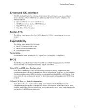
... BIOS Setup program after you install a PCI/PCI Express add-in card in card. 17 PCI and PCI Express Auto Configuration If you install a PCI/PCI Express add-in your computer. Expandability The desktop board supports the following: • One PCI Express x16 add-in card • One PCI Express x1 add-in card • Two PCI add-in cards Related Links: For information...
... BIOS Setup program after you install a PCI/PCI Express add-in card in card. 17 PCI and PCI Express Auto Configuration If you install a PCI/PCI Express add-in your computer. Expandability The desktop board supports the following: • One PCI Express x16 add-in card • One PCI Express x1 add-in card • Two PCI add-in cards Related Links: For information...

Intel Desktop Board D101GGC Product Guide English
Page 43
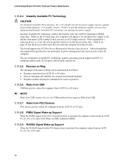
Location of the PCI bus add-in card connector 1 PCI Express x1 connector Chassis intrusion connector Diskette drive connector D OM18221 Figure 22. ABC Item A B C D E E Description PCI bus add-in card connector 2 PCI bus add-in card, PCI Express x1, chassis intrusion, and diskette drive connectors. Installing and Replacing Desktop Board Components Other Connectors Figure 22 shows the location of Other Connectors on Desktop Board D101GGC 43
Location of the PCI bus add-in card connector 1 PCI Express x1 connector Chassis intrusion connector Diskette drive connector D OM18221 Figure 22. ABC Item A B C D E E Description PCI bus add-in card connector 2 PCI bus add-in card, PCI Express x1, chassis intrusion, and diskette drive connectors. Installing and Replacing Desktop Board Components Other Connectors Figure 22 shows the location of Other Connectors on Desktop Board D101GGC 43

