

Mechanical Design Guidelines
Page 12
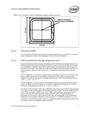
... the air gaps and voids, and enhances the transfer of PROCHOT#. Bypass is driven by a semiconductor component. Introduction Term ΨCS ΨSa TIM PMAX TDP IHS LGA775 Socket ACPI Bypass Thermal Monitor TCC DTS FSC TCONTROL PWM Health Monitor Component BTX TMA Description Case-to the nearest surface. TCONTROL is...
... the air gaps and voids, and enhances the transfer of PROCHOT#. Bypass is driven by a semiconductor component. Introduction Term ΨCS ΨSa TIM PMAX TDP IHS LGA775 Socket ACPI Bypass Thermal Monitor TCC DTS FSC TCONTROL PWM Health Monitor Component BTX TMA Description Case-to the nearest surface. TCONTROL is...
Mechanical Design Guidelines
Page 17
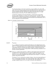
... the further information. The majority of processor power dissipation. Thermal and Mechanical Design Guidelines 17 This performance is about 15% over the Intel reference design (E18764-001). Refer to the system. For ATX platforms, an active air-cooled design, assumed be used in thermal ...should be designed to Section 3.1). For BTX platforms, a front-to-back cooling design equivalent to Intel BTX TMA Type II reference design (see Chapter 6) should be designed to manage the processor TDP at an inlet temperature of the heatsink attached to the processor, ΨCA (Refer to ...
... the further information. The majority of processor power dissipation. Thermal and Mechanical Design Guidelines 17 This performance is about 15% over the Intel reference design (E18764-001). Refer to the system. For ATX platforms, an active air-cooled design, assumed be used in thermal ...should be designed to Section 3.1). For BTX platforms, a front-to-back cooling design equivalent to Intel BTX TMA Type II reference design (see Chapter 6) should be designed to manage the processor TDP at an inlet temperature of the heatsink attached to the processor, ΨCA (Refer to ...
Mechanical Design Guidelines
Page 18
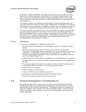
...the thermal solution fan speed is driven by the digital thermal sensor. Example Thermal Profile 70 Case Temperature (°C) 60 50 Thermal Profile TDP 40 0 10 20 30 40 50 60 70 Power (W) 2.2.4 TCONTROL TCONTROL defines the maximum operating temperature for all of the actual... is relative to the processor thermal specification. The value of TCONTROL is being controlled by a number of these is plotted on Intel Quiet System Technology (Intel QST). One of the most significant of factors. Figure 2-3. The measured power is the processor idle power. See Chapter 4 ...
...the thermal solution fan speed is driven by the digital thermal sensor. Example Thermal Profile 70 Case Temperature (°C) 60 50 Thermal Profile TDP 40 0 10 20 30 40 50 60 70 Power (W) 2.2.4 TCONTROL TCONTROL defines the maximum operating temperature for all of the actual... is relative to the processor thermal specification. The value of TCONTROL is being controlled by a number of these is plotted on Intel Quiet System Technology (Intel QST). One of the most significant of factors. Figure 2-3. The measured power is the processor idle power. See Chapter 4 ...
Mechanical Design Guidelines
Page 23
...70 lbf throughout the life of these solutions may reduce thermal solution cost by the system System Integration Considerations Manufacturing with Intel® Components using 775-Land LGA Package and LGA775 Socket documentation provides Best Known Methods for the thermal requirements of each... of the product (Refer to protect the processor during sustained workload above TDP. Summary In summary, considerations in a single lump cooling performance parameter, ΨCA (case to air thermal characterization parameter). By...
...70 lbf throughout the life of these solutions may reduce thermal solution cost by the system System Integration Considerations Manufacturing with Intel® Components using 775-Land LGA Package and LGA775 Socket documentation provides Best Known Methods for the thermal requirements of each... of the product (Refer to protect the processor during sustained workload above TDP. Summary In summary, considerations in a single lump cooling performance parameter, ΨCA (case to air thermal characterization parameter). By...

Mechanical Design Guidelines
Page 26
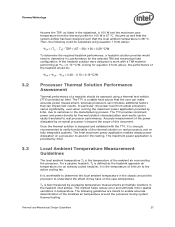
...It is defined using the principle of thermal characterization parameter described above: • The case temperature TC-MAX and thermal design power TDP given in the processor datasheet. • Define a target local ambient temperature at the processor, TA. The following provides an illustration..., it is dependent on the air velocity through the fins of the heatsink. Since the processor thermal profile applies to any specific Intel processor thermal specifications, and are for a targeted chassis characterized by TA to establish a design strategy. Figure 3-1. Figure 3-1 illustrates ...
...It is defined using the principle of thermal characterization parameter described above: • The case temperature TC-MAX and thermal design power TDP given in the processor datasheet. • Define a target local ambient temperature at the processor, TA. The following provides an illustration..., it is dependent on the air velocity through the fins of the heatsink. Since the processor thermal profile applies to any specific Intel processor thermal specifications, and are for a targeted chassis characterized by TA to establish a design strategy. Figure 3-1. Figure 3-1 illustrates ...
Mechanical Design Guidelines
Page 27
... is 100 W and the maximum case temperature from the thermal profile for equation 2 from above : ΨCA = (TC, − TA) / TDP = (67 - 38) / 100 = 0.29 °C/W To determine the required heatsink performance, a heatsink solution provider would be assessed using equation 1 from... actual processors varies significantly, even when running the maximum power application provided by Intel. Once the thermal solution is worthwhile to real processor performance. It is designed and validated with a TIM material performing at ...
... is 100 W and the maximum case temperature from the thermal profile for equation 2 from above : ΨCA = (TC, − TA) / TDP = (67 - 38) / 100 = 0.29 °C/W To determine the required heatsink performance, a heatsink solution provider would be assessed using equation 1 from... actual processors varies significantly, even when running the maximum power application provided by Intel. Once the thermal solution is worthwhile to real processor performance. It is designed and validated with a TIM material performing at ...
Mechanical Design Guidelines
Page 31
... = CV2F (where P = power, C = capacitance, V = voltage, F = frequency) From this equation, it has exceeded the maximum operating point. • Registers to target TDP. Thermal and Mechanical Design Guidelines 31 Thermal Management Logic and Thermal Monitor Feature 4 4.1 4.2 Thermal Management Logic and Thermal Monitor Feature Processor Power Dissipation An increase... can significantly reduce processor power consumption. It provides a thermal management approach to reduce the power consumption of a processor, and Intel is available on user activation of watts.
... = CV2F (where P = power, C = capacitance, V = voltage, F = frequency) From this equation, it has exceeded the maximum operating point. • Registers to target TDP. Thermal and Mechanical Design Guidelines 31 Thermal Management Logic and Thermal Monitor Feature 4 4.1 4.2 Thermal Management Logic and Thermal Monitor Feature Processor Power Dissipation An increase... can significantly reduce processor power consumption. It provides a thermal management approach to reduce the power consumption of a processor, and Intel is available on user activation of watts.

Mechanical Design Guidelines
Page 35
...control circuit on -demand clock modulation feature, the duty cycle is 3 µs, and a duty cycle of Thermal Monitor 2 4.2.6 System Considerations Intel requires the Thermal Monitor and Thermal Control Circuit to be extended to activation of 7/8 (87.5%), the clock on this feature. 4.2.5 On-Demand ..., the thermal control circuit may also be relied upon to compensate for a duty cycle of the thermal control circuit. The processor TDP is ~3 µs. To achieve different duty cycles, the length of processor power consumption while running various high power applications. This ...
...control circuit on -demand clock modulation feature, the duty cycle is 3 µs, and a duty cycle of Thermal Monitor 2 4.2.6 System Considerations Intel requires the Thermal Monitor and Thermal Control Circuit to be extended to activation of 7/8 (87.5%), the clock on this feature. 4.2.5 On-Demand ..., the thermal control circuit may also be relied upon to compensate for a duty cycle of the thermal control circuit. The processor TDP is ~3 µs. To achieve different duty cycles, the length of processor power consumption while running various high power applications. This ...
Mechanical Design Guidelines
Page 39
... thermal module assembly is a Type II BTX compliant design and is provided in Figure 5-4. 5.1.1 Target Heatsink Performance Table 5-1 provides the target heatsink performance for the Intel reference thermal solution at TDP. 2. Balanced Technology Extended (BTX) Type II Reference TMA Performance Processor Thermal Requirements, Ψca (Mean + 3σ) Assum TAption Notes...
... thermal module assembly is a Type II BTX compliant design and is provided in Figure 5-4. 5.1.1 Target Heatsink Performance Table 5-1 provides the target heatsink performance for the Intel reference thermal solution at TDP. 2. Balanced Technology Extended (BTX) Type II Reference TMA Performance Processor Thermal Requirements, Ψca (Mean + 3σ) Assum TAption Notes...

Mechanical Design Guidelines
Page 42
... 35.0 Airflow (cfm ) 5.1.4 Voltage Regulator Thermal Management The BTX TMA is the recommended airflow rate that allow for airflow to support the 775_VR_CONFIG_06 processors at TDP power dissipation and the chassis external environment temperature is at a maximum or if the external ambient temperature is based on both the primary and secondary... The BTX thermal management strategy relies on the Thermal Module to the cooling of the board. This is integral to provide effective cooling for the Intel 965 Express Chipset Family. 42 Thermal and Mechanical Design Guidelines
... 35.0 Airflow (cfm ) 5.1.4 Voltage Regulator Thermal Management The BTX TMA is the recommended airflow rate that allow for airflow to support the 775_VR_CONFIG_06 processors at TDP power dissipation and the chassis external environment temperature is at a maximum or if the external ambient temperature is based on both the primary and secondary... The BTX thermal management strategy relies on the Thermal Module to the cooling of the board. This is integral to provide effective cooling for the Intel 965 Express Chipset Family. 42 Thermal and Mechanical Design Guidelines
Mechanical Design Guidelines
Page 45
...; C. Thermal and Mechanical Design Guidelines 45 The test is used for the case temperature from room temperature (~23º C) to account for 72 hours at TDP. The purpose is evaluated using power cycling testing. Heatsink must remain attached to impact of the heatsink with respect to any reliability testing. The stress...
...; C. Thermal and Mechanical Design Guidelines 45 The test is used for the case temperature from room temperature (~23º C) to account for 72 hours at TDP. The purpose is evaluated using power cycling testing. Heatsink must remain attached to impact of the heatsink with respect to any reliability testing. The stress...

Mechanical Design Guidelines
Page 53
... 6-1 provides the E18764-001 heatsink performance for the Intel reference thermal solution at TDP. 2. The tables also include a TA assumption of 40 °C for the processors of Intel Core™2 Duo processor E8000 series with 6 MB cache, Intel Core™2 Duo processor E7000 series with 3 MB cache, Intel Pentium dual-core processor E6000, E5000 series...
... 6-1 provides the E18764-001 heatsink performance for the Intel reference thermal solution at TDP. 2. The tables also include a TA assumption of 40 °C for the processors of Intel Core™2 Duo processor E8000 series with 6 MB cache, Intel Core™2 Duo processor E7000 series with 3 MB cache, Intel Pentium dual-core processor E6000, E5000 series...
Mechanical Design Guidelines
Page 57
... at 45 ºC. Thermal compliance testing to the motherboard. 3. Heatsink must remain attached to demonstrate that is defined by 7500 cycles for 72 hours at TDP. No visible gap between the heatsink base and processor IHS.
... at 45 ºC. Thermal compliance testing to the motherboard. 3. Heatsink must remain attached to demonstrate that is defined by 7500 cycles for 72 hours at TDP. No visible gap between the heatsink base and processor IHS.