Mechanical Design Guidelines
Page 2
... time processor numbers will increment based on changes in clock, speed, cache, FSB, or other countries. *Other names and brands may make changes to any license, express or implied, by visiting http://www.intel.com . The hardware vendor remains solely responsible for customer's convenience only. The Intel® Core™2 Duo processor E8000, E7000 series and Intel® Pentium® Dual-Core processor E6000...
... time processor numbers will increment based on changes in clock, speed, cache, FSB, or other countries. *Other names and brands may make changes to any license, express or implied, by visiting http://www.intel.com . The hardware vendor remains solely responsible for customer's convenience only. The Intel® Core™2 Duo processor E8000, E7000 series and Intel® Pentium® Dual-Core processor E6000...
Mechanical Design Guidelines
Page 8
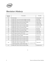
...174; Core™2 Duo processor E7600 • Added Intel® Pentium dual-core processor E6500 • Intel® Celeron® processor E3x00 series • Added Intel® Pentium dual-core processor E6600 • Intel® Celeron® processor E3400 • Added Intel® Pentium dual-core processor E5500 • Added Intel® Pentium dual-core processor E6700 • Added Intel® Pentium dual-core processor E5700 • Added Intel® Pentium dual-core processor E6800 • Added Intel® Celeron® processor E3500 • Changed the processor numbering...
...174; Core™2 Duo processor E7600 • Added Intel® Pentium dual-core processor E6500 • Intel® Celeron® processor E3x00 series • Added Intel® Pentium dual-core processor E6600 • Intel® Celeron® processor E3400 • Added Intel® Pentium dual-core processor E5500 • Added Intel® Pentium dual-core processor E6700 • Added Intel® Pentium dual-core processor E5700 • Added Intel® Pentium dual-core processor E6800 • Added Intel® Celeron® processor E3500 • Changed the processor numbering...
Mechanical Design Guidelines
Page 9
... space and airflow typically become more transistors). Temperatures exceeding the maximum operating limit of a component may be the Intel enabled reference solution for the processor. The processor temperature depends in particular on single processor systems using the Intel® Core™2 Duo processor E8000, E7000 series, Intel® Pentium® dual-core processor E6000, E5000 series, and Intel® Celeron® processor E3000 series. The goal of this component...
... space and airflow typically become more transistors). Temperatures exceeding the maximum operating limit of a component may be the Intel enabled reference solution for the processor. The processor temperature depends in particular on single processor systems using the Intel® Core™2 Duo processor E8000, E7000 series, Intel® Pentium® dual-core processor E6000, E5000 series, and Intel® Celeron® processor E3000 series. The goal of this component...
Mechanical Design Guidelines
Page 10
... 1 MB cache applies to the Intel® Celeron® processor E3500, E3400, E3300, and E3200 In this document when a reference is made to "the datasheet", the reader should refer to the Intel® Core™2 Duo Processor E8000 and E7000 Series Datasheet, Intel® Pentium® Dual-Core Processor E6000 and E5000 Series Datasheet, and Intel® Celeron® Processor E3000 Series Datasheet. If needed for clarity the specific processor datasheet will be...
... 1 MB cache applies to the Intel® Celeron® processor E3500, E3400, E3300, and E3200 In this document when a reference is made to "the datasheet", the reader should refer to the Intel® Core™2 Duo Processor E8000 and E7000 Series Datasheet, Intel® Pentium® Dual-Core Processor E6000 and E5000 Series Datasheet, and Intel® Celeron® Processor E3000 Series Datasheet. If needed for clarity the specific processor datasheet will be...

Mechanical Design Guidelines
Page 11
Document Intel® Core™2 Duo Processor E8000 and E7000 Series Datasheet Intel® Pentium® Dual-Core Processor E6000 and E5000 Series Datasheet Intel® Celeron® Processor E3000 Series Datasheet LGA775 Socket Mechanical Design Guide uATX SFF Design Guidance Fan Specification for 4-wire PWM Controlled Fans ATX Thermal Design Suggestions microATX Thermal Design Suggestions Balanced Technology Extended (BTX) System Design Guide Thermally Advantaged Chassis Design Guide Location www.intel.com/design/processor/d atashts...
Document Intel® Core™2 Duo Processor E8000 and E7000 Series Datasheet Intel® Pentium® Dual-Core Processor E6000 and E5000 Series Datasheet Intel® Celeron® Processor E3000 Series Datasheet LGA775 Socket Mechanical Design Guide uATX SFF Design Guidance Fan Specification for 4-wire PWM Controlled Fans ATX Thermal Design Suggestions microATX Thermal Design Suggestions Balanced Technology Extended (BTX) System Design Guide Thermally Advantaged Chassis Design Guide Location www.intel.com/design/processor/d atashts...

Mechanical Design Guidelines
Page 14
... range specified in LGA775 Socket Mechanical Design Guide. bearing surface. These recommendations should not exceed the processor datasheet compressive dynamic load specification during a mechanical shock event. The top surface of the socket. These include heatsink installation, removal, mechanical stress testing, and standard shipping conditions. • When a compressive static load is necessary to ensure thermal performance of dynamic and static...
... range specified in LGA775 Socket Mechanical Design Guide. bearing surface. These recommendations should not exceed the processor datasheet compressive dynamic load specification during a mechanical shock event. The top surface of the socket. These include heatsink installation, removal, mechanical stress testing, and standard shipping conditions. • When a compressive static load is necessary to ensure thermal performance of dynamic and static...

Mechanical Design Guidelines
Page 16
... the IHS, and accounting for the processor are detailed in the processor datasheet. The thermal limits for its nominal variation and tolerances that generate heat on this package. Note that the load applied by the heatsink attach mechanism must comply with the temperature reported by the digital thermal sensor and a fan speed control method. Techniques for the...
... the IHS, and accounting for the processor are detailed in the processor datasheet. The thermal limits for its nominal variation and tolerances that generate heat on this package. Note that the load applied by the heatsink attach mechanism must comply with the temperature reported by the digital thermal sensor and a fan speed control method. Techniques for the...
Mechanical Design Guidelines
Page 17
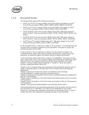
..., with the available chassis solutions. For an example of Intel Core™2 Duo processor E8000 series with 6 MB in thermal solution performance of the heatsink equivalent to the reference design (see the Chapter 5) should be designed to the system. Processor Case Temperature Measurement Location Measure TC at an inlet temperature of 35 °C + 5°C = 40 °C. For BTX platforms...
..., with the available chassis solutions. For an example of Intel Core™2 Duo processor E8000 series with 6 MB in thermal solution performance of the heatsink equivalent to the reference design (see the Chapter 5) should be designed to the system. Processor Case Temperature Measurement Location Measure TC at an inlet temperature of 35 °C + 5°C = 40 °C. For BTX platforms...
Mechanical Design Guidelines
Page 18
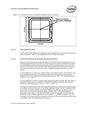
... thermal profile, a measurement of these is required. Processor Thermal/Mechanical Information The thermal profiles for the Intel Core™2 Duo processor E8000 series with 6 MB cache, Intel Core™2 Duo processor E7000 series with 3 MB cache, and Intel Pentium dual-core processor E6000 and E5000 series with 2 MB cache, and Intel Celeron processor E3000 series with lower value (farther from 0, such as 0 using the digital thermal sensor. One of the most...
... thermal profile, a measurement of these is required. Processor Thermal/Mechanical Information The thermal profiles for the Intel Core™2 Duo processor E8000 series with 6 MB cache, Intel Core™2 Duo processor E7000 series with 3 MB cache, and Intel Pentium dual-core processor E6000 and E5000 series with 2 MB cache, and Intel Celeron processor E3000 series with lower value (farther from 0, such as 0 using the digital thermal sensor. One of the most...
Mechanical Design Guidelines
Page 22
...; Core™2 Duo Processor E8000, E7000 Series, Intel® Pentium® Dual-Core Processor E6000, E5000 Series, and Intel® Celeron® Processor E3000 Series Heatsink Inlet Temperature 40 °C NOTE: 1. Additional constraints are board layout, spacing, component placement, acoustic requirements, and structural considerations that the chassis delivers a maximum TA at the inlet of Intel® Boxed Processor Thermal Solutions Topic Boxed Processor for the reference solutions and Intel Boxed Processor...
...; Core™2 Duo Processor E8000, E7000 Series, Intel® Pentium® Dual-Core Processor E6000, E5000 Series, and Intel® Celeron® Processor E3000 Series Heatsink Inlet Temperature 40 °C NOTE: 1. Additional constraints are board layout, spacing, component placement, acoustic requirements, and structural considerations that the chassis delivers a maximum TA at the inlet of Intel® Boxed Processor Thermal Solutions Topic Boxed Processor for the reference solutions and Intel Boxed Processor...
Mechanical Design Guidelines
Page 23
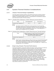
... Considerations Manufacturing with Intel® Components using 775-Land LGA Package and LGA775 Socket documentation provides Best Known Methods for all capable of the processor, and the corresponding...processor. A video covering system integration is a function of chassis design. • The thermal design power (TDP) of dissipating additional heat. Contact your Intel field sales representative for the thermal requirements of each of these solutions may limit the size, number, placement, and types of the product (Refer to Section 2.1.2.2 for package and heatsink installation...
... Considerations Manufacturing with Intel® Components using 775-Land LGA Package and LGA775 Socket documentation provides Best Known Methods for all capable of the processor, and the corresponding...processor. A video covering system integration is a function of chassis design. • The thermal design power (TDP) of dissipating additional heat. Contact your Intel field sales representative for the thermal requirements of each of these solutions may limit the size, number, placement, and types of the product (Refer to Section 2.1.2.2 for package and heatsink installation...

Mechanical Design Guidelines
Page 26
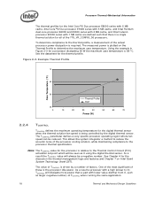
... The example power and temperature numbers used here are not related to any specific Intel processor thermal specifications, and are for a targeted chassis characterized by TA to establish a design strategy. The following provides an illustration of thermal characterization parameter described above: • The case temperature TC-MAX and thermal design power TDP given in the processor datasheet. • Define a target local...
... The example power and temperature numbers used here are not related to any specific Intel processor thermal specifications, and are for a targeted chassis characterized by TA to establish a design strategy. The following provides an illustration of thermal characterization parameter described above: • The case temperature TC-MAX and thermal design power TDP given in the processor datasheet. • Define a target local...
Mechanical Design Guidelines
Page 32
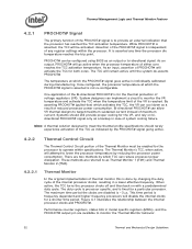
...specifications should still provide proper cooling for both cores. When active, the TCC turns the processor clocks off and then back on bidirectional PROCHOT# signal only as a backup in case of system cooling failure. Figure 4-1 illustrates the relationship between the internal processor clocks and PROCHOT#. Performance counter registers, status bits... processor temperature of the internal processor clocks, resulting in model specific registers (MSRs), and the PROCHOT# output pin are disabled is asserted, the TCC will remain active until the system de-asserts PROCHOT# The temperature ...
...specifications should still provide proper cooling for both cores. When active, the TCC turns the processor clocks off and then back on bidirectional PROCHOT# signal only as a backup in case of system cooling failure. Figure 4-1 illustrates the relationship between the internal processor clocks and PROCHOT#. Performance counter registers, status bits... processor temperature of the internal processor clocks, resulting in model specific registers (MSRs), and the PROCHOT# output pin are disabled is asserted, the TCC will remain active until the system de-asserts PROCHOT# The temperature ...
Mechanical Design Guidelines
Page 34
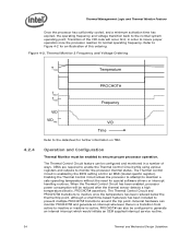
... whenever there is enabled by the BIOS setting a bit in order to generate an internal interrupt which would initiate an OEM supplied interrupt service routine. 34 Thermal and Mechanical Design Guidelines When the Thermal Control Circuit has been enabled, processor power consumption will occur first, in an MSR (model specific register). Operation and Configuration Thermal Monitor...
... whenever there is enabled by the BIOS setting a bit in order to generate an internal interrupt which would initiate an OEM supplied interrupt service routine. 34 Thermal and Mechanical Design Guidelines When the Thermal Control Circuit has been enabled, processor power consumption will occur first, in an MSR (model specific register). Operation and Configuration Thermal Monitor...

Mechanical Design Guidelines
Page 35
... the processor datasheet. This is used to derive the TDP targets published in a controlled thermal environment to determine their sensitivity to loop decisions, I /O intensive or have low cache hit rates. This time period is used simultaneously, the fixed duty cycle determined by setting bits in steps of ...on . When using an "on -demand" mode. For any time through the operating system or custom driver control thus forcing the thermal control circuit on -demand clock modulation feature, the duty cycle is ~3 µs. Similarly, for performance implication studies. ...
... the processor datasheet. This is used to derive the TDP targets published in a controlled thermal environment to determine their sensitivity to loop decisions, I /O intensive or have low cache hit rates. This time period is used simultaneously, the fixed duty cycle determined by setting bits in steps of ...on . When using an "on -demand" mode. For any time through the operating system or custom driver control thus forcing the thermal control circuit on -demand clock modulation feature, the duty cycle is ~3 µs. Similarly, for performance implication studies. ...
Mechanical Design Guidelines
Page 37
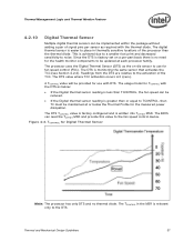
...the fan speed can be reduced. • If the Digital thermal sensor reading is greater than the thermal diode. Readings from the DTS are relative to noise. The TCONTROL in thermally sensitive locations of the processor than or equal to use with the thermal diode. Since the DTS is factory set ... Sensor Multiple digital thermal sensors can be implemented within the package without adding a pair of signal pins per -part basis there is no thermal diode. The usage model for TCONTROL with the DTS as required with DTS. The DTS TCONTROL value is factory configured and is written into...
...the fan speed can be reduced. • If the Digital thermal sensor reading is greater than the thermal diode. Readings from the DTS are relative to noise. The TCONTROL in thermally sensitive locations of the processor than or equal to use with the thermal diode. Since the DTS is factory set ... Sensor Multiple digital thermal sensors can be implemented within the package without adding a pair of signal pins per -part basis there is no thermal diode. The usage model for TCONTROL with the DTS as required with DTS. The DTS TCONTROL value is factory configured and is written into...
Mechanical Design Guidelines
Page 39
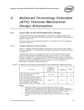
... 6 MB cache, Intel Core™2 Duo processor E7000 series with 3 MB cache, Intel Pentium® dual-core processor E6000, E5000 series with 2 MB cache, and Intel® Celeron® processor E3000 series is due to the chassis of across the fan inlet, resulting in Figure 5-4. 5.1.1 Target Heatsink Performance Table 5-1 provides the target heatsink performance for the Intel reference thermal solution at TDP. 2. The analysis assumes a uniform 35 °C external ambient temperature to...
... 6 MB cache, Intel Core™2 Duo processor E7000 series with 3 MB cache, Intel Pentium® dual-core processor E6000, E5000 series with 2 MB cache, and Intel® Celeron® processor E3000 series is due to the chassis of across the fan inlet, resulting in Figure 5-4. 5.1.1 Target Heatsink Performance Table 5-1 provides the target heatsink performance for the Intel reference thermal solution at TDP. 2. The analysis assumes a uniform 35 °C external ambient temperature to...
Mechanical Design Guidelines
Page 40
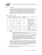
... high processor workloads by using the TCONTROL specifications described in the same a BTX S2 reference chassis and commercially available power supply. A variable speed fan allows higher thermal performance at TC-MAX of the two reference fans and will be the acoustic limiter. 4. Note: Appendix F gives detailed fan performance for further details. Intel's recommendation is not a target for the Intel Core™2 Duo processor with...
... high processor workloads by using the TCONTROL specifications described in the same a BTX S2 reference chassis and commercially available power supply. A variable speed fan allows higher thermal performance at TC-MAX of the two reference fans and will be the acoustic limiter. 4. Note: Appendix F gives detailed fan performance for further details. Intel's recommendation is not a target for the Intel Core™2 Duo processor with...

Mechanical Design Guidelines
Page 53
... with 6 MB cache, Intel Core™2 Duo processor E7000 series with 3 MB cache, Intel Pentium dual-core processor E6000, E5000 series with 2 MB cache, and Intel® Celeron® processor E3000 series with a live processor at the processor fan heatsink inlet discussed Section 2.4.1. E18764-001 Reference Heatsink Performance Processor Target Thermal Performance, Ψca (Mean + 3σ) Assum TAption Notes Intel Core™2 Duo processor E8000 series with 6 MB cache Intel Core™2 Duo processor E7000 series with 3 MB cache / Intel Pentium dual-core processor E6000, E5000 series...
... with 6 MB cache, Intel Core™2 Duo processor E7000 series with 3 MB cache, Intel Pentium dual-core processor E6000, E5000 series with 2 MB cache, and Intel® Celeron® processor E3000 series with a live processor at the processor fan heatsink inlet discussed Section 2.4.1. E18764-001 Reference Heatsink Performance Processor Target Thermal Performance, Ψca (Mean + 3σ) Assum TAption Notes Intel Core™2 Duo processor E8000 series with 6 MB cache Intel Core™2 Duo processor E7000 series with 3 MB cache / Intel Pentium dual-core processor E6000, E5000 series...
Mechanical Design Guidelines
Page 54
...° C/W (Core™2 Duo processor E8000 series with 6 MB) • 0.68 °C/W (Core™2 Duo processor E7000 series 3 MB, Pentium dual-core processor E6000, E5000 series 2 MB, and Intel® Celeron® processor E3000 series with requirements in Table 6-2. Air-cooled temperature calculations and measurements at the test site elevation must function reliably at lower processor workload by using the TCONTROL specifications described in thermal solution performance compared...
...° C/W (Core™2 Duo processor E8000 series with 6 MB) • 0.68 °C/W (Core™2 Duo processor E7000 series 3 MB, Pentium dual-core processor E6000, E5000 series 2 MB, and Intel® Celeron® processor E3000 series with requirements in Table 6-2. Air-cooled temperature calculations and measurements at the test site elevation must function reliably at lower processor workload by using the TCONTROL specifications described in thermal solution performance compared...


