
Mechanical Design Guidelines
Page 4
...43 5.2.1.2 Shock Test Procedure 44 5.2.2 Power Cycling 45 5.2.3 Recommended BIOS/CPU/Memory Test Procedures 46 5.3 Material and Recycling Requirements 46 5.4 Safety Requirements 47 5.5 Geometric Envelope for Intel® Reference BTX Thermal Module Assembly ......47 5.6 Preload and TMA ...55 6.3.1.2 Shock Test Procedure 56 6.3.2 Power Cycling 57 6.3.3 Recommended BIOS/CPU/Memory Test Procedures 58 6.4 Material and Recycling Requirements 58 6.5 Safety Requirements 59 6.6 Geometric Envelope for Intel® Reference ATX Thermal Mechanical Design.....59 6.7 Reference Attach Mechanism 60...
...43 5.2.1.2 Shock Test Procedure 44 5.2.2 Power Cycling 45 5.2.3 Recommended BIOS/CPU/Memory Test Procedures 46 5.3 Material and Recycling Requirements 46 5.4 Safety Requirements 47 5.5 Geometric Envelope for Intel® Reference BTX Thermal Module Assembly ......47 5.6 Preload and TMA ...55 6.3.1.2 Shock Test Procedure 56 6.3.2 Power Cycling 57 6.3.3 Recommended BIOS/CPU/Memory Test Procedures 58 6.4 Material and Recycling Requirements 58 6.5 Safety Requirements 59 6.6 Geometric Envelope for Intel® Reference ATX Thermal Mechanical Design.....59 6.7 Reference Attach Mechanism 60...
Mechanical Design Guidelines
Page 45
...; C. No signs of physical damage on motherboard surface due to impact of the heatsink with a visual inspection after assembly, and BIOS/CPU/Memory test (refer to TIM degradation is defined by 7500 cycles for the case temperature from room temperature (~23º C) to account... is evaluated using power cycling testing. A Thermal Test Vehicle is to the maximum case temperature defined by a visual inspection and then BIOS/CPU/Memory test. 5.2.1.2.2 Post-Test Pass Criteria The post-test pass criteria are: 1. Thermal and Mechanical Design Guidelines 45 Heatsink must remain attached...
...; C. No signs of physical damage on motherboard surface due to impact of the heatsink with a visual inspection after assembly, and BIOS/CPU/Memory test (refer to TIM degradation is defined by 7500 cycles for the case temperature from room temperature (~23º C) to account... is evaluated using power cycling testing. A Thermal Test Vehicle is to the maximum case temperature defined by a visual inspection and then BIOS/CPU/Memory test. 5.2.1.2.2 Post-Test Pass Criteria The post-test pass criteria are: 1. Thermal and Mechanical Design Guidelines 45 Heatsink must remain attached...

Mechanical Design Guidelines
Page 46
Balanced Technology Extended (BTX) Thermal/Mechanical Design Information 5.2.3 5.3 Recommended BIOS/CPU/Memory Test Procedures This test is that contain organic fillers of laminating materials, paints, and varnishes also are not fungal growth resistant, then MILSTD-810E, ...
Balanced Technology Extended (BTX) Thermal/Mechanical Design Information 5.2.3 5.3 Recommended BIOS/CPU/Memory Test Procedures This test is that contain organic fillers of laminating materials, paints, and varnishes also are not fungal growth resistant, then MILSTD-810E, ...
Mechanical Design Guidelines
Page 57
...load relaxation during burn-in stage. Successful BIOS/Processor/memory test of the heatsink with a visual inspection after assembly, and BIOS/CPU/Memory test (refer to impact of physical damage on motherboard surface due to Section 6.3.3). Thermal compliance testing to demonstrate that have ...the heatsink attach mechanism (including such items as clip and motherboard fasteners). 2. The test is defined by a visual inspection and then BIOS/CPU/Memory test. 6.3.1.2.2 Post-Test Pass Criteria The post-test pass criteria are: 1. Prior to the processor package. 6. No visible physical...
...load relaxation during burn-in stage. Successful BIOS/Processor/memory test of the heatsink with a visual inspection after assembly, and BIOS/CPU/Memory test (refer to impact of physical damage on motherboard surface due to Section 6.3.3). Thermal compliance testing to demonstrate that have ...the heatsink attach mechanism (including such items as clip and motherboard fasteners). 2. The test is defined by a visual inspection and then BIOS/CPU/Memory test. 6.3.1.2.2 Post-Test Pass Criteria The post-test pass criteria are: 1. Prior to the processor package. 6. No visible physical...

Mechanical Design Guidelines
Page 58
ATX Thermal/Mechanical Design Information 6.3.3 6.4 Recommended BIOS/CPU/Memory Test Procedures This test is that the system under test shall successfully complete the checking of laminating materials, paints, and varnishes also are not ...
ATX Thermal/Mechanical Design Information 6.3.3 6.4 Recommended BIOS/CPU/Memory Test Procedures This test is that the system under test shall successfully complete the checking of laminating materials, paints, and varnishes also are not ...

Mechanical Design Guidelines
Page 110
....00 36.78 41.00 45.26 47.50 SOCKET BALL 1 ( 19.13 ) PACKAGE BOUNDARY A NOTES: 1. DIMENSIONS ARE IN MILLIMETERS. 2 GEOMETRIC CENTER OF CPU PACKAGE / SOCKET HOUSING CAVITY. 3. P.O. ASSUME SYMMETRY FOR UNDIMENSIONED CORNERS AND EDGES. 8 7 6 ( 1.17 ) (0.965 ) 36.00 31.51 PIN 1 ...COMPONENET KEEP-OUTS TO BE UTILIZED WITH SUFFICIENT ALLOWANCES FOR PLACEMENT AND SIZE TOLERANCES, ASSEMBLY PROCESS ACCESS, AND DYNAMIC EXCURSIONS. 4. CORP. BOX 58119 A SANTA CLARA, CA 95052-8119 TITLE THIRD ANGLE PROJECTION APPROVED BY DATE LGA775 microATX APPROVED BY DATE MATERIAL: N/A FINISH: N/A...
....00 36.78 41.00 45.26 47.50 SOCKET BALL 1 ( 19.13 ) PACKAGE BOUNDARY A NOTES: 1. DIMENSIONS ARE IN MILLIMETERS. 2 GEOMETRIC CENTER OF CPU PACKAGE / SOCKET HOUSING CAVITY. 3. P.O. ASSUME SYMMETRY FOR UNDIMENSIONED CORNERS AND EDGES. 8 7 6 ( 1.17 ) (0.965 ) 36.00 31.51 PIN 1 ...COMPONENET KEEP-OUTS TO BE UTILIZED WITH SUFFICIENT ALLOWANCES FOR PLACEMENT AND SIZE TOLERANCES, ASSEMBLY PROCESS ACCESS, AND DYNAMIC EXCURSIONS. 4. CORP. BOX 58119 A SANTA CLARA, CA 95052-8119 TITLE THIRD ANGLE PROJECTION APPROVED BY DATE LGA775 microATX APPROVED BY DATE MATERIAL: N/A FINISH: N/A...
Mechanical Design Guidelines
Page 112
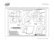
...00 120.0 1.00 30.00 3.80 8.15 2 LEVER MOTION SPACE REQUIRED TO RELEASE ( 46.11 ) SOCKET LOAD PLATE B 5.80 3 DWG. BOX 58119 SANTA CLARA, CA 95052-8119 2 SIZE CAGE CODE DRAWING NUMBER REV D C40819 3 SCALE: NONE DONOT SCALE DRAWING SHEET 3 OF 3 1 ...112 Thermal and Mechanical Design Guidelines CORP. Sheet 3 8 THIS DRAWING CONTAINS INTEL CORPORAT MAY NOT BE DISCLOSED, REPRODUCED, DI D 1 7 ION CONFIDENTIAL INFORMATION. IT ENCOMPASSES SOCKET AND CPU PACKAGE DIMENSIONAL TOLERANCES AND DEFLECTION / SHAPE CHANGES DUE TO DSL LOAD. 3. SOCKET KEEP-IN VOLUME...
...00 120.0 1.00 30.00 3.80 8.15 2 LEVER MOTION SPACE REQUIRED TO RELEASE ( 46.11 ) SOCKET LOAD PLATE B 5.80 3 DWG. BOX 58119 SANTA CLARA, CA 95052-8119 2 SIZE CAGE CODE DRAWING NUMBER REV D C40819 3 SCALE: NONE DONOT SCALE DRAWING SHEET 3 OF 3 1 ...112 Thermal and Mechanical Design Guidelines CORP. Sheet 3 8 THIS DRAWING CONTAINS INTEL CORPORAT MAY NOT BE DISCLOSED, REPRODUCED, DI D 1 7 ION CONFIDENTIAL INFORMATION. IT ENCOMPASSES SOCKET AND CPU PACKAGE DIMENSIONAL TOLERANCES AND DEFLECTION / SHAPE CHANGES DUE TO DSL LOAD. 3. SOCKET KEEP-IN VOLUME...
