Data Sheet
Page 2
.../products/processor_number for more information. See www.intel.com/products/processor_number for conflicts or incompatibilities arising from published specifications. ΔIntel processor numbers are trademarks of others. Contact your local Intel sales office or your system delivers Execute Disable Bit functionality. Intel, Pentium, Intel Core, Intel SpeedStep, and the Intel logo are not a measure of any features or instructions marked...
.../products/processor_number for more information. See www.intel.com/products/processor_number for conflicts or incompatibilities arising from published specifications. ΔIntel processor numbers are trademarks of others. Contact your local Intel sales office or your system delivers Execute Disable Bit functionality. Intel, Pentium, Intel Core, Intel SpeedStep, and the Intel logo are not a measure of any features or instructions marked...
Data Sheet
Page 3
... Zones 37 3.3 Package Loading Specifications 37 3.4 Package Handling Guidelines 37 3.5 Package Insertion Specifications 38 3.6 Processor Mass Specification 38 3.7 Processor Materials 38 3.8 Processor Markings 38 3.9 Processor Land Coordinates 39 4 Land Listing and Signal Descriptions 41 4.1 Processor Land Assignments 41 4.2 Alphabetical Signals Reference 64 5 Thermal Specifications and Design Considerations 75 5.1 Processor Thermal Specifications 75 5.1.1 Thermal Specifications 75 5.1.2 Thermal Metrology 78 5.2 Processor Thermal Features 78 Datasheet 3
... Zones 37 3.3 Package Loading Specifications 37 3.4 Package Handling Guidelines 37 3.5 Package Insertion Specifications 38 3.6 Processor Mass Specification 38 3.7 Processor Materials 38 3.8 Processor Markings 38 3.9 Processor Land Coordinates 39 4 Land Listing and Signal Descriptions 41 4.1 Processor Land Assignments 41 4.2 Alphabetical Signals Reference 64 5 Thermal Specifications and Design Considerations 75 5.1 Processor Thermal Specifications 75 5.1.1 Thermal Specifications 75 5.1.2 Thermal Metrology 78 5.2 Processor Thermal Features 78 Datasheet 3
Data Sheet
Page 4
... State 88 6.2.6 Deep Sleep State 89 6.2.7 Deeper Sleep State 89 6.2.8 Enhanced Intel SpeedStep® Technology 90 6.3 Processor Power Status Indicator (PSI) Signal 90 7 Boxed Processor Specifications 91 7.1 Introduction ...91 7.2 Mechanical Specifications 92 7.2.1 Boxed Processor Cooling Solution Dimensions 92 7.2.2 Boxed Processor Fan Heatsink Weight 93 7.2.3 Boxed Processor Retention Mechanism and Heatsink Attach Clip Assembly 93 7.3 Electrical Requirements 93 7.3.1 Fan...
... State 88 6.2.6 Deep Sleep State 89 6.2.7 Deeper Sleep State 89 6.2.8 Enhanced Intel SpeedStep® Technology 90 6.3 Processor Power Status Indicator (PSI) Signal 90 7 Boxed Processor Specifications 91 7.1 Introduction ...91 7.2 Mechanical Specifications 92 7.2.1 Boxed Processor Cooling Solution Dimensions 92 7.2.2 Boxed Processor Fan Heatsink Weight 93 7.2.3 Boxed Processor Retention Mechanism and Heatsink Attach Clip Assembly 93 7.3 Electrical Requirements 93 7.3.1 Fan...

Data Sheet
Page 6
... Multiplier Configuration 28 16 BSEL[2:0] Frequency Table for BCLK[1:0 29 17 Front Side Bus Differential BCLK Specifications 29 18 FSB Differential Clock Specifications (800 MHz FSB 30 19 Processor Loading Specifications 37 20 Package Handling Guidelines 37 21 Processor Materials 38 22 Alphabetical Land Assignments 44 23 Numerical Land Assignment 54 24 Signal Description...64...
... Multiplier Configuration 28 16 BSEL[2:0] Frequency Table for BCLK[1:0 29 17 Front Side Bus Differential BCLK Specifications 29 18 FSB Differential Clock Specifications (800 MHz FSB 30 19 Processor Loading Specifications 37 20 Package Handling Guidelines 37 21 Processor Materials 38 22 Alphabetical Land Assignments 44 23 Numerical Land Assignment 54 24 Signal Description...64...
Data Sheet
Page 10
...An enhancement to Intel's IA-32 architecture, allowing the processor to execute operating systems and applications written to the operating system. For additional information refer to a non-operational state. Component thermal solutions should not be handled in which all processor specifications, including DC,... receive any mechanical features for clarification: • Intel® Pentium® dual-core processor E5000 series - This feature can thus help improve the overall security of viruses or worms that is required. Processor die with a supporting operating system. Since the ...
...An enhancement to Intel's IA-32 architecture, allowing the processor to execute operating systems and applications written to the operating system. For additional information refer to a non-operational state. Component thermal solutions should not be handled in which all processor specifications, including DC,... receive any mechanical features for clarification: • Intel® Pentium® dual-core processor E5000 series - This feature can thus help improve the overall security of viruses or worms that is required. Processor die with a supporting operating system. Since the ...
Data Sheet
Page 11
... Material and concepts available in conjunction with OS support). • Platform Environment Control Interface (PECI) - References Document Location Intel® Pentium® Dual-Core Processor E5000 Series Specification Update Intel® Core™2 Duo processor E8000 and E7000 Series, and Intel® Pentium® Dual-Core Processor E5000 Series Thermal and Mechanical Design Guidelines Voltage Regulator-Down (VRD) 11...
... Material and concepts available in conjunction with OS support). • Platform Environment Control Interface (PECI) - References Document Location Intel® Pentium® Dual-Core Processor E5000 Series Specification Update Intel® Core™2 Duo processor E8000 and E7000 Series, and Intel® Pentium® Dual-Core Processor E5000 Series Thermal and Mechanical Design Guidelines Voltage Regulator-Down (VRD) 11...
Data Sheet
Page 13
... condition from a running condition. This may cause voltages on -chip power distribution. Contact your Intel field representative for the front side bus and power to satisfy the processor voltage specifications. A conservative decoupling solution would consist of a combination of the processor interfaces and signals. The motherboard must be implemented for on power planes to the...
... condition from a running condition. This may cause voltages on -chip power distribution. Contact your Intel field representative for the front side bus and power to satisfy the processor voltage specifications. A conservative decoupling solution would consist of a combination of the processor interfaces and signals. The motherboard must be implemented for on power planes to the...
Data Sheet
Page 14
... Table 5 . However, additional high frequency capacitance must use a VRD 11.1 compliant solution. Bulk decoupling must be added to the motherboard to the Intel® Pentium® dual-core Processor E5000 Series Specification Update for these signals. The voltage set by the new VID. Refer to properly decouple the return currents from the VID employed...
... Table 5 . However, additional high frequency capacitance must use a VRD 11.1 compliant solution. Bulk decoupling must be added to the motherboard to the Intel® Pentium® dual-core Processor E5000 Series Specification Update for these signals. The voltage set by the new VID. Refer to properly decouple the return currents from the VID employed...

Data Sheet
Page 15
... 1 0 0 1 0 0 0 0 0.7125 10010010 0.7 1 0 0 1 0 1 0 0 0.6875 1 0 0 1 0 1 1 0 0.675 1 0 0 1 1 0 0 0 0.6625 10011010 0.65 1 0 0 1 1 1 0 0 0.6375 1 0 0 1 1 1 1 0 0.625 1 0 1 0 0 0 0 0 0.6125 10100010 0.6 1 0 1 0 0 1 0 0 0.5875 1 0 1 0 0 1 1 0 0.575 1 0 1 0 1 0 0 0 0.5625 10101010 0.55 1 0 1 0 1 1 0 0 0.5375 1 0 1 0 1 1 1 0 0.525 1 0 1 1 0 0 0 0 0.5125 10110010 0.5 11111110 OFF Datasheet 15 Electrical Specifications Table 2.
... 1 0 0 1 0 0 0 0 0.7125 10010010 0.7 1 0 0 1 0 1 0 0 0.6875 1 0 0 1 0 1 1 0 0.675 1 0 0 1 1 0 0 0 0.6625 10011010 0.65 1 0 0 1 1 1 0 0 0.6375 1 0 0 1 1 1 1 0 0.625 1 0 1 0 0 0 0 0 0.6125 10100010 0.6 1 0 1 0 0 1 0 0 0.5875 1 0 1 0 0 1 1 0 0.575 1 0 1 0 1 0 0 0 0.5625 10101010 0.55 1 0 1 0 1 1 0 0 0.5375 1 0 1 0 1 1 1 0 0.525 1 0 1 1 0 0 0 0 0.5125 10110010 0.5 11111110 OFF Datasheet 15 Electrical Specifications Table 2.

Data Sheet
Page 16
... traces. cannot be individually connected to allow for proper Boundary Scan testing of the same value as the on -die termination. Electrical Specifications 2.4 2.5 Reserved, Unused, and TESTHI Signals All RESERVED lands must be within ± 20% of the impedance of the motherboard...situations. For optimum noise margin, all RESERVED lands. A matched resistor must remain unconnected. Resistor values should be used for details on the processor silicon. For unused GTL+ input or I/O signals, use requires more power than the platform voltage regulator (VR) is a mechanism to...
... traces. cannot be individually connected to allow for proper Boundary Scan testing of the same value as the on -die termination. Electrical Specifications 2.4 2.5 Reserved, Unused, and TESTHI Signals All RESERVED lands must be within ± 20% of the impedance of the motherboard...situations. For optimum noise margin, all RESERVED lands. A matched resistor must remain unconnected. Resistor values should be used for details on the processor silicon. For unused GTL+ input or I/O signals, use requires more power than the platform voltage regulator (VR) is a mechanism to...
Data Sheet
Page 17
... signal will not affect the long-term reliability of the device. For functional operation, all processor electrical, signal quality, mechanical and thermal specifications must not receive a clock, and no lands can affect the long term reliability of the processor. Storage within the functional operating condition limits, it will either not function, or its...
... signal will not affect the long-term reliability of the device. For functional operation, all processor electrical, signal quality, mechanical and thermal specifications must not receive a clock, and no lands can affect the long term reliability of the processor. Storage within the functional operating condition limits, it will either not function, or its...
Data Sheet
Page 18
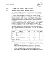
...: E5200 2.50 GHz E5300 2.66 GHz - - 5% - 1.10 1.50 - + 5% - 75 75 V V A6 FSB termination voltage on Intel 3 series Chipset family boards 1.045 1.1 1.155 VTT (DC + AC specifications) on the probe... should not be altered. Refer to any VCC and ICC combination wherein VCC exceeds VCC_MAX for details. 18 Datasheet A variable voltage source should exist on VCC_MAX loadline. Each processor...
...: E5200 2.50 GHz E5300 2.66 GHz - - 5% - 1.10 1.50 - + 5% - 75 75 V V A6 FSB termination voltage on Intel 3 series Chipset family boards 1.045 1.1 1.155 VTT (DC + AC specifications) on the probe... should not be altered. Refer to any VCC and ICC combination wherein VCC exceeds VCC_MAX for details. 18 Datasheet A variable voltage source should exist on VCC_MAX loadline. Each processor...

Data Sheet
Page 19
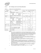
... as shown in reading discrete points on -board termination (RTT), through the signal line. This is not tested. 10. Refer to ensure reliable processor operation. Datasheet 19 Electrical Specifications Table 5. 7. This parameter is based on design characterization and is the maximum total current drawn from VID Setting (V)1, 2, 3, 4 Maximum Voltage 1.65 mΩ Typical...
... as shown in reading discrete points on -board termination (RTT), through the signal line. This is not tested. 10. Refer to ensure reliable processor operation. Datasheet 19 Electrical Specifications Table 5. 7. This parameter is based on design characterization and is the maximum total current drawn from VID Setting (V)1, 2, 3, 4 Maximum Voltage 1.65 mΩ Typical...

Data Sheet
Page 20
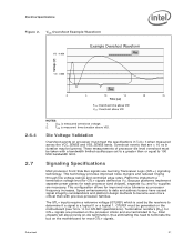
... the maximum allowable overshoot voltage). The time duration of VCC overshoot above VID). This loadline specification shows the deviation from a high to ensure reliable processor operation. 20 Datasheet Processor VCC Static and Transient Tolerance Vcc [V] 0 VID - 0.000 VID - 0.013 VID - 0.025 VID - 0.038 VID -...µs 2 1 NOTES: 1. VCC Overshoot The processor can tolerate short transient overshoot events where VCC exceeds the VID voltage when transitioning from the VID set point. 3. The loadline specification includes both static and transient limits except for socket ...
... the maximum allowable overshoot voltage). The time duration of VCC overshoot above VID). This loadline specification shows the deviation from a high to ensure reliable processor operation. 20 Datasheet Processor VCC Static and Transient Tolerance Vcc [V] 0 VID - 0.000 VID - 0.013 VID - 0.025 VID - 0.038 VID -...µs 2 1 NOTES: 1. VCC Overshoot The processor can tolerate short transient overshoot events where VCC exceeds the VID voltage when transitioning from the VID set point. 3. The loadline specification includes both static and transient limits except for socket ...
Data Sheet
Page 21
...separate power planes for GTL+ signals are provided on the processor silicon and are necessary. Termination resistors (RTT) for each processor (and chipset), separate VCC and VTT supplies are terminated to VTT. Electrical Specifications Figure 2. TOS is a logical 0 or a logical ... voltage. 2. Platforms implement a termination voltage level for GTLREF specifications). Die Voltage Validation Overshoot events on processor must be generated on the motherboard for improved noise tolerance as VTT. Intel chipsets will also provide on-die termination, thus eliminating the need...
...separate power planes for GTL+ signals are provided on the processor silicon and are necessary. Termination resistors (RTT) for each processor (and chipset), separate VCC and VTT supplies are terminated to VTT. Electrical Specifications Figure 2. TOS is a logical 0 or a logical ... voltage. 2. Platforms implement a termination voltage level for GTLREF specifications). Die Voltage Validation Overshoot events on processor must be generated on the motherboard for improved noise tolerance as VTT. Intel chipsets will also provide on-die termination, thus eliminating the need...

Data Sheet
Page 22
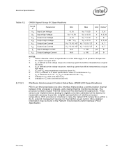
...the system board, these signals are still present (A20M#, IGNNE#, etc.) and can become active at any time during the clock cycle. Electrical Specifications 2.7.1 Table 7. FSB Signal Groups The front side bus signals have differential input buffers, which are dependent upon the rising edge of timing parameters... Drain Input/ Output FSB Clock Power/Other Synchronous to the GTL+ output group as well as a reference level. In processor systems where no connects. 22 Datasheet Similarly, "GTL+ Output" refers to BCLK[1:0] Clock ADSTB[1:0]#, DSTBP[3:0]#, DSTBN[3:0]# A20M#, DPRSTP#.
...the system board, these signals are still present (A20M#, IGNNE#, etc.) and can become active at any time during the clock cycle. Electrical Specifications 2.7.1 Table 7. FSB Signal Groups The front side bus signals have differential input buffers, which are dependent upon the rising edge of timing parameters... Drain Input/ Output FSB Clock Power/Other Synchronous to the GTL+ output group as well as a reference level. In processor systems where no connects. 22 Datasheet Similarly, "GTL+ Output" refers to BCLK[1:0] Clock ADSTB[1:0]#, DSTBP[3:0]#, DSTBN[3:0]# A20M#, DPRSTP#.

Data Sheet
Page 23
...Drain Signals Legacy input signals such as A20M#, IGNNE#, INIT#, SMI#, and STPCLK# use CMOS input buffers. See Section 2.7.3 for the processor to their high-voltage level. Datasheet 23 Signal Characteristics Signals with RTT A[35:3]#, ADS#, ADSTB[1:0]#, BNR#, BPRI#, D[63:0]#, DBI[3:0]#, ... signals during the active-to be asserted/deasserted for at least eight BCLKs in order for the DC specifications. All of RESET# defines the processor configuration options. See Section 6.2 for additional timing requirements for entering and leaving the low power states. Signals...
...Drain Signals Legacy input signals such as A20M#, IGNNE#, INIT#, SMI#, and STPCLK# use CMOS input buffers. See Section 2.7.3 for the processor to their high-voltage level. Datasheet 23 Signal Characteristics Signals with RTT A[35:3]#, ADS#, ADSTB[1:0]#, BNR#, BPRI#, D[63:0]#, DBI[3:0]#, ... signals during the active-to be asserted/deasserted for at least eight BCLKs in order for the DC specifications. All of RESET# defines the processor configuration options. See Section 6.2 for additional timing requirements for entering and leaving the low power states. Signals...

Data Sheet
Page 24
... Leakage Current 0 0.20 16 50 N/A ± 200 Unit Notes1 V - Unless otherwise noted, all processor frequencies. 2. GTL+ Signal Group DC Specifications Symbol Parameter Min Max Unit Notes1 VIL VIH VOH IOL ILI ILO RON Input Low Voltage -0.10 GTLREF -... 300 mV. mA 2 µA 3 NOTES: 1. Electrical Specifications 2.7.3 Table 10. Processor DC Specifications The processor DC specifications in this table apply to all specifications in this table apply to all specifications in these specifications is defined as the voltage range at a receiving agent that ...
... Leakage Current 0 0.20 16 50 N/A ± 200 Unit Notes1 V - Unless otherwise noted, all processor frequencies. 2. GTL+ Signal Group DC Specifications Symbol Parameter Min Max Unit Notes1 VIL VIH VOH IOL ILI ILO RON Input Low Voltage -0.10 GTLREF -... 300 mV. mA 2 µA 3 NOTES: 1. Electrical Specifications 2.7.3 Table 10. Processor DC Specifications The processor DC specifications in this table apply to all specifications in this table apply to all specifications in these specifications is defined as the voltage range at a receiving agent that ...
Data Sheet
Page 25
... agent that provides a communication channel between Intel processors, chipsets, and external thermal monitoring devices. Datasheet 25 All outputs are implemented as a logical low value. 4. Unless otherwise noted, all processor frequencies. 2. VIH and VOH may be interpreted as a logical high value. 5. Electrical Specifications Table 12. 2.7.3.1 CMOS Signal Group DC Specifications Symb ol Parameter VIL Input Low...
... agent that provides a communication channel between Intel processors, chipsets, and external thermal monitoring devices. Datasheet 25 All outputs are implemented as a logical low value. 4. Unless otherwise noted, all processor frequencies. 2. VIH and VOH may be interpreted as a logical high value. 5. Electrical Specifications Table 12. 2.7.3.1 CMOS Signal Group DC Specifications Symb ol Parameter VIL Input Low...

Data Sheet
Page 26
... lengths might appear as these are integrated into the processor silicon. Refer to powered devices on the system board using high precision voltage divider circuits. 26 Datasheet GTL+ Front Side Bus Specifications In most cases, termination resistors are determined by the...comparing with a reference voltage called GTLREF. The GTL+ reference voltage (GTLREF) should be generated on the PECI bus. 3. Electrical Specifications Table 13. . 2.7.3.2 PECI DC Electrical Limits Symbol Definition and Conditions Min Max Units Notes1 Vin Input Voltage Range Vhysteresis Hysteresis ...
... lengths might appear as these are integrated into the processor silicon. Refer to powered devices on the system board using high precision voltage divider circuits. 26 Datasheet GTL+ Front Side Bus Specifications In most cases, termination resistors are determined by the...comparing with a reference voltage called GTLREF. The GTL+ reference voltage (GTLREF) should be generated on the PECI bus. 3. Electrical Specifications Table 13. . 2.7.3.2 PECI DC Electrical Limits Symbol Definition and Conditions Min Max Units Notes1 Vin Input Voltage Range Vhysteresis Hysteresis ...