
Data Sheet
Page 4
... State 88 6.2.6 Deep Sleep State 89 6.2.7 Deeper Sleep State 89 6.2.8 Enhanced Intel SpeedStep® Technology 90 6.3 Processor Power Status Indicator (PSI) Signal 90 7 Boxed Processor Specifications 91 7.1 Introduction ...91 7.2 Mechanical Specifications 92 7.2.1 Boxed Processor Cooling Solution Dimensions 92 7.2.2 Boxed Processor Fan Heatsink Weight 93 7.2.3 Boxed Processor Retention Mechanism and Heatsink Attach Clip Assembly 93 7.3 Electrical Requirements 93...
... State 88 6.2.6 Deep Sleep State 89 6.2.7 Deeper Sleep State 89 6.2.8 Enhanced Intel SpeedStep® Technology 90 6.3 Processor Power Status Indicator (PSI) Signal 90 7 Boxed Processor Specifications 91 7.1 Introduction ...91 7.2 Mechanical Specifications 92 7.2.1 Boxed Processor Cooling Solution Dimensions 92 7.2.2 Boxed Processor Fan Heatsink Weight 93 7.2.3 Boxed Processor Retention Mechanism and Heatsink Attach Clip Assembly 93 7.3 Electrical Requirements 93...

Data Sheet
Page 5
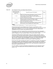
... Waveform 30 4 Measurement Points for the Boxed Processor 93 22 Boxed Processor Fan Heatsink Power Cable Connector Description 94 23 Baseboard Power Header Placement Relative to Processor Socket 95 24 Boxed Processor Fan Heatsink Airspace Keepout Requirements (side 1 view 96 25 Boxed Processor Fan Heatsink Airspace Keepout Requirements (side 2 view 96 26 Boxed Processor Fan Heatsink Set Points 97 Datasheet 5
... Waveform 30 4 Measurement Points for the Boxed Processor 93 22 Boxed Processor Fan Heatsink Power Cable Connector Description 94 23 Baseboard Power Header Placement Relative to Processor Socket 95 24 Boxed Processor Fan Heatsink Airspace Keepout Requirements (side 1 view 96 25 Boxed Processor Fan Heatsink Airspace Keepout Requirements (side 2 view 96 26 Boxed Processor Fan Heatsink Set Points 97 Datasheet 5

Data Sheet
Page 6
... 38 22 Alphabetical Land Assignments 44 23 Numerical Land Assignment 54 24 Signal Description...64 25 Processor Thermal Specifications 76 26 Processor Thermal Profile 77 27 GetTemp0() Error Codes 83 28 Power-On Configuration Option Signals 85 29 Fan Heatsink Power and Signal Specifications 94 30 Fan Heatsink Power and Signal Specifications 98 6 Datasheet
... 38 22 Alphabetical Land Assignments 44 23 Numerical Land Assignment 54 24 Signal Description...64 25 Processor Thermal Specifications 76 26 Processor Thermal Profile 77 27 GetTemp0() Error Codes 83 28 Power-On Configuration Option Signals 85 29 Fan Heatsink Power and Signal Specifications 94 30 Fan Heatsink Power and Signal Specifications 98 6 Datasheet
Data Sheet
Page 25
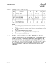
... as the voltage range at the factory for thermal/fan speed control. VIH is measured at 300 mV. Platform Environment Control Interface (PECI) DC Specifications PECI is an Intel proprietary one-wire interface that will be interpreted as...A 6, 7 VTT * 0.10 / 67 VTT * 0.10 / 27 A 6, 7 N/A ± 100 µA 8 N/A ± 100 µA 9 NOTES: 1. Leakage to all processor frequencies. 2. The processor contains Digital Thermal Sensors (DTS) distributed throughout die. Unless otherwise noted, all specifications in this table apply to VSS with land held at a receiving...
... as the voltage range at the factory for thermal/fan speed control. VIH is measured at 300 mV. Platform Environment Control Interface (PECI) DC Specifications PECI is an Intel proprietary one-wire interface that will be interpreted as...A 6, 7 VTT * 0.10 / 67 VTT * 0.10 / 27 A 6, 7 N/A ± 100 µA 8 N/A ± 100 µA 9 NOTES: 1. Leakage to all processor frequencies. 2. The processor contains Digital Thermal Sensors (DTS) distributed throughout die. Unless otherwise noted, all specifications in this table apply to VSS with land held at a receiving...
Data Sheet
Page 75
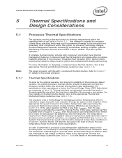
...Thermal and Mechanical Design Guidelines (see Section 1.2). The processor uses a methodology for the details of system fans combined with a component thermal solution. Selection of Intel processor-based systems, the system/processor thermal solution should be designed to take these operating ... (TCC) activation, as set forth in Section 5.3. Intel has developed a methodology for the optimal operation and long-term reliability of the appropriate fan speed is necessary to accurately measure processor power dissipation. Thermal Specifications and Design Considerations 5 Thermal ...
...Thermal and Mechanical Design Guidelines (see Section 1.2). The processor uses a methodology for the details of system fans combined with a component thermal solution. Selection of Intel processor-based systems, the system/processor thermal solution should be designed to take these operating ... (TCC) activation, as set forth in Section 5.3. Intel has developed a methodology for the optimal operation and long-term reliability of the appropriate fan speed is necessary to accurately measure processor power dissipation. Thermal Specifications and Design Considerations 5 Thermal ...

Data Sheet
Page 82
... Platform Environment Control Interface (PECI) Specification. 5.3.1.1 Figure 16. The PECI interface on the processor is covered in detail in the Platform Environment Control Interface Specification. Conceptual Fan Control Diagram on PECI-Based Platforms 5.3.2 5.3.2.1 5.3.2.2 PECI Specifications PECI Device Address The PECI... it contains no sign bit. TCONTROL and TCC activation on PECI-Based Systems Fan speed control solutions based on PECI utilize a TCONTROL value stored in the processor IA32_TEMPERATURE_TARGET MSR. The TCONTROL MSR uses the same offset temperature format as indicated...
... Platform Environment Control Interface (PECI) Specification. 5.3.1.1 Figure 16. The PECI interface on the processor is covered in detail in the Platform Environment Control Interface Specification. Conceptual Fan Control Diagram on PECI-Based Platforms 5.3.2 5.3.2.1 5.3.2.2 PECI Specifications PECI Device Address The PECI... it contains no sign bit. TCONTROL and TCC activation on PECI-Based Systems Fan speed control solutions based on PECI utilize a TCONTROL value stored in the processor IA32_TEMPERATURE_TARGET MSR. The TCONTROL MSR uses the same offset temperature format as indicated...

Data Sheet
Page 91
... dimensions should not be supplied with the boxed processor. Mechanical Representation of the Boxed Processor NOTE: The airflow of the fan heatsink is particularly important for OEMs that will be offered as a generic keep -out zone on the Intel boxed processor product. Boxed Processor Specifications 7 Boxed Processor Specifications 7.1 Introduction The processor will also be supplied with a cooling solution...
... dimensions should not be supplied with the boxed processor. Mechanical Representation of the Boxed Processor NOTE: The airflow of the fan heatsink is particularly important for OEMs that will be offered as a generic keep -out zone on the Intel boxed processor product. Boxed Processor Specifications 7 Boxed Processor Specifications 7.1 Introduction The processor will also be supplied with a cooling solution...

Data Sheet
Page 92
... View) 95.0 [3.74] 81.3 [3.2] 10.0 [0.39] 25.0 [0.98] Figure 20. The airspace requirements for the boxed processor with an unattached fan heatsink. Figure 19. The boxed processor will be incorporated into new baseboard and system designs. Note that some figures have centerlines shown (marked with alphabetic designations) to ensure unimpeded airflow for ...
... View) 95.0 [3.74] 81.3 [3.2] 10.0 [0.39] 25.0 [0.98] Figure 20. The airspace requirements for the boxed processor with an unattached fan heatsink. Figure 19. The boxed processor will be incorporated into new baseboard and system designs. Note that some figures have centerlines shown (marked with alphabetic designations) to ensure unimpeded airflow for ...

Data Sheet
Page 93
...pin 3 of the connector labeled as CONTROL. Datasheet 93 A baseboard pull-up resistor provides VOH to support the boxed processor. A fan power cable will not weigh more than 450 grams. See Chapter 5 and the appropriate Thermal and Mechanical Design Guidelines (see... socket. collector output that pulses at the fan heatsink connector. Overall View Space Requirements for the Boxed Processor 7.2.2 7.2.3 7.3 7.3.1 Boxed Processor Fan Heatsink Weight The boxed processor fan heatsink will be tied to secure the processor and fan heatsink in Figure 22. Baseboards must provide ...
...pin 3 of the connector labeled as CONTROL. Datasheet 93 A baseboard pull-up resistor provides VOH to support the boxed processor. A fan power cable will not weigh more than 450 grams. See Chapter 5 and the appropriate Thermal and Mechanical Design Guidelines (see... socket. collector output that pulses at the fan heatsink connector. Overall View Space Requirements for the Boxed Processor 7.2.2 7.2.3 7.3 7.3.1 Boxed Processor Fan Heatsink Weight The boxed processor fan heatsink will be tied to secure the processor and fan heatsink in Figure 22. Baseboards must provide ...

Data Sheet
Page 94
... to reach it. The baseboard power header should be documented in the platform documentation, or on the system board itself. A Second pulses per fan 1 revolution kHz 2, 3 94 Datasheet Boxed Processor Fan Heatsink Power Cable Connector Description Pin Signal 1 GND 2 +12 V 3 SENSE 4 CONTROL Straight square pin, 4-pin terminal housing with a resistor. 2. Match with straight...
... to reach it. The baseboard power header should be documented in the platform documentation, or on the system board itself. A Second pulses per fan 1 revolution kHz 2, 3 94 Datasheet Boxed Processor Fan Heatsink Power Cable Connector Description Pin Signal 1 GND 2 +12 V 3 SENSE 4 CONTROL Straight square pin, 4-pin terminal housing with a resistor. 2. Match with straight...

Data Sheet
Page 95
... acceptable airspace clearance for the fan heatsink. The boxed processor fan heatsink is into the center and out of the sides of the fan heatsink solution used by the boxed processor. Airflow of the fan heatsink is able to the fan heatsink is also a function... good thermal management. However, meeting the processor's temperature specification is the responsibility of the system integrator. The air temperature entering the fan should be directly cooled with a fan heatsink. Boxed Processor Cooling Requirements The boxed processor may be kept below 38 ºC. Baseboard...
... acceptable airspace clearance for the fan heatsink. The boxed processor fan heatsink is into the center and out of the sides of the fan heatsink solution used by the boxed processor. Airflow of the fan heatsink is able to the fan heatsink is also a function... good thermal management. However, meeting the processor's temperature specification is the responsibility of the system integrator. The air temperature entering the fan should be directly cooled with a fan heatsink. Boxed Processor Cooling Requirements The boxed processor may be kept below 38 ºC. Baseboard...
Data Sheet
Page 97
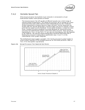
...internal chassis temperature should be kept below 38 ºC. Boxed Processor Specifications 7.4.2 Variable Speed Fan If the boxed processor fan heatsink 4-pin connector is connected to Table 29 for the boxed processor. Systems should be designed to operate at its maximum. If... Z Internal Chassis Temperature (Degrees C) Datasheet 97 Meeting the processor's temperature specification (see Chapter 5) is reached. This allows the processor fan to provide adequate air around the boxed processor fan heatsink that point, the fan speed is at a lower speed and noise level, while ...
...internal chassis temperature should be kept below 38 ºC. Boxed Processor Specifications 7.4.2 Variable Speed Fan If the boxed processor fan heatsink 4-pin connector is connected to Table 29 for the boxed processor. Systems should be designed to operate at its maximum. If... Z Internal Chassis Temperature (Degrees C) Datasheet 97 Meeting the processor's temperature specification (see Chapter 5) is reached. This allows the processor fan to provide adequate air around the boxed processor fan heatsink that point, the fan speed is at a lower speed and noise level, while ...
Data Sheet
Page 98
...below or equal to this set point, the fan operates at the fan inlet. Set point variance is at its lowest and highest speeds. Fan Heatsink Power and Signal Specifications Boxed Processor Fan Heatsink Set Point (°C) Boxed Processor Fan Speed Notes X ≤ 30 When the ... highest speed. - Recommended maximum internal chassis temperature for 4-wire based fan speed control, refer to the 4th pin of internal ambient chassis temperatures. Intel has added an option to the boxed processor that sends out a PWM control signal to the appropriate Thermal and Mechanical...
...below or equal to this set point, the fan operates at the fan inlet. Set point variance is at its lowest and highest speeds. Fan Heatsink Power and Signal Specifications Boxed Processor Fan Heatsink Set Point (°C) Boxed Processor Fan Speed Notes X ≤ 30 When the ... highest speed. - Recommended maximum internal chassis temperature for 4-wire based fan speed control, refer to the 4th pin of internal ambient chassis temperatures. Intel has added an option to the boxed processor that sends out a PWM control signal to the appropriate Thermal and Mechanical...