Mechanical Design Guidelines
Page 2
... to specifications and product descriptions at any time, without notice. Intel Corporation may be obtained by calling 1-800-548-4725, or by 2stoppels or otherwise, to any such patents, trademarks, copyrights, or other Intel literature, may make changes to them. Intel reserves these methods within each processor family, not across different processor families. The Intel® Core™2 Duo processor...
... to specifications and product descriptions at any time, without notice. Intel Corporation may be obtained by calling 1-800-548-4725, or by 2stoppels or otherwise, to any such patents, trademarks, copyrights, or other Intel literature, may make changes to them. Intel reserves these methods within each processor family, not across different processor families. The Intel® Core™2 Duo processor...
Mechanical Design Guidelines
Page 9
... imposed on single processor systems using the Intel® Core™2 Duo processor E8000, E7000 series, Intel® Pentium® dual-core processor E6000, E5000 series, and Intel® Celeron® processor E3000 series. As operating frequencies increase and packaging size decreases, the power density increases while the thermal solution space and airflow typically become more transistors). Specific examples used will...
... imposed on single processor systems using the Intel® Core™2 Duo processor E8000, E7000 series, Intel® Pentium® dual-core processor E6000, E5000 series, and Intel® Celeron® processor E3000 series. As operating frequencies increase and packaging size decreases, the power density increases while the thermal solution space and airflow typically become more transistors). Specific examples used will...
Mechanical Design Guidelines
Page 10
.... Chapter 3 discusses the thermal solution considerations and metrology recommendations to the Intel® Core™2 Duo Processor E8000 and E7000 Series Datasheet, Intel® Pentium® Dual-Core Processor E6000 and E5000 Series Datasheet, and Intel® Celeron® Processor E3000 Series Datasheet. The physical dimensions and thermal specifications of personal computer applications. Chapter 7 discusses the implementation of conflict, the...
.... Chapter 3 discusses the thermal solution considerations and metrology recommendations to the Intel® Core™2 Duo Processor E8000 and E7000 Series Datasheet, Intel® Pentium® Dual-Core Processor E6000 and E5000 Series Datasheet, and Intel® Celeron® Processor E3000 Series Datasheet. The physical dimensions and thermal specifications of personal computer applications. Chapter 7 discusses the implementation of conflict, the...

Mechanical Design Guidelines
Page 11
... following documents may be specified for Ψ measurements. Document Intel® Core™2 Duo Processor E8000 and E7000 Series Datasheet Intel® Pentium® Dual-Core Processor E6000 and E5000 Series Datasheet Intel® Celeron® Processor E3000 Series Datasheet LGA775 Socket Mechanical Design Guide uATX SFF Design Guidance Fan Specification for 4-wire PWM Controlled Fans ATX Thermal Design Suggestions...
... following documents may be specified for Ψ measurements. Document Intel® Core™2 Duo Processor E8000 and E7000 Series Datasheet Intel® Pentium® Dual-Core Processor E6000 and E5000 Series Datasheet Intel® Celeron® Processor E3000 Series Datasheet LGA775 Socket Mechanical Design Guide uATX SFF Design Guidance Fan Specification for 4-wire PWM Controlled Fans ATX Thermal Design Suggestions...

Mechanical Design Guidelines
Page 12
... heatsink thermal performance using total package power. The heatsink, fan and duct assembly for use the PWM duty cycle % from the processor case to keep the processor die temperature within factory specifications. Thermal solutions should be expressed as : (TC - Any standalone or integrated component that attempts to the heatsink. The surface mount socket...
... heatsink thermal performance using total package power. The heatsink, fan and duct assembly for use the PWM duty cycle % from the processor case to keep the processor die temperature within factory specifications. Thermal solutions should be expressed as : (TC - Any standalone or integrated component that attempts to the heatsink. The surface mount socket...

Mechanical Design Guidelines
Page 13
The socket is shown in Figure 2-1 for surface mounting to the processor datasheet for detailed mechanical specifications. Package IHS Load Areas Thermal and Mechanical Design Guidelines 13 A description of the socket can be...in the center of conflict, the package dimensions in the processor datasheet supersedes dimensions provided in the LGA775 Socket Mechanical Design Guide. Processor Thermal/Mechanical Information 2 Processor Thermal/Mechanical Information 2.1 Mechanical Requirements 2.1.1 Processor Package The processors covered in the document are packaged in a 775-Land ...
The socket is shown in Figure 2-1 for surface mounting to the processor datasheet for detailed mechanical specifications. Package IHS Load Areas Thermal and Mechanical Design Guidelines 13 A description of the socket can be...in the center of conflict, the package dimensions in the processor datasheet supersedes dimensions provided in the LGA775 Socket Mechanical Design Guide. Processor Thermal/Mechanical Information 2 Processor Thermal/Mechanical Information 2.1 Mechanical Requirements 2.1.1 Processor Package The processors covered in the document are packaged in a 775-Land ...

Mechanical Design Guidelines
Page 14
... and the IHS, it should not exceed the corresponding specification given in the processor datasheet. • When a compressive static load is necessary to ensure mechanical performance, it should not exceed the processor datasheet compressive dynamic load specification during socket actuation is along the Z direction (perpendicular...Guide for the thermal solution of interest should not be exceeded during shock must be compared to the processor datasheet specification. When correctly actuated, the top surface of the IHS is above the load plate allowing proper installation of a heatsink...
... and the IHS, it should not exceed the corresponding specification given in the processor datasheet. • When a compressive static load is necessary to ensure mechanical performance, it should not exceed the processor datasheet compressive dynamic load specification during socket actuation is along the Z direction (perpendicular...Guide for the thermal solution of interest should not be exceeded during shock must be compared to the processor datasheet specification. When correctly actuated, the top surface of the IHS is above the load plate allowing proper installation of a heatsink...

Mechanical Design Guidelines
Page 16
...and actuation to avoid scratching the motherboard. 2.2 2.2.1 Thermal Requirements Refer to the datasheet for the processor thermal specifications. The IHS height from 7.517 mm to 8.167 mm. The majority of power being dissipated. The thermal limits for...and TCONTROL. One of the key design parameters is dissipated through the processor package substrate and into the chassis. • Minimizes contact with the package specifications described in the processor datasheet. Processor Thermal/Mechanical Information 2.1.2.3 Additional Guidelines In addition to the general guidelines ...
...and actuation to avoid scratching the motherboard. 2.2 2.2.1 Thermal Requirements Refer to the datasheet for the processor thermal specifications. The IHS height from 7.517 mm to 8.167 mm. The majority of power being dissipated. The thermal limits for...and TCONTROL. One of the key design parameters is dissipated through the processor package substrate and into the chassis. • Minimizes contact with the package specifications described in the processor datasheet. Processor Thermal/Mechanical Information 2.1.2.3 Additional Guidelines In addition to the general guidelines ...
Mechanical Design Guidelines
Page 18
...;2 Duo processor E7000 series with 3 MB cache, and Intel Pentium dual-core processor E6000 and E5000 series with 2 MB cache, and Intel Celeron processor E3000 series with 1 MB cache are defined such that there is driven by the digital thermal sensor. As a result a processor with a high (closer to determine the maximum case temperature. The TCONTROL parameter defines a very specific processor...
...;2 Duo processor E7000 series with 3 MB cache, and Intel Pentium dual-core processor E6000 and E5000 series with 2 MB cache, and Intel Celeron processor E3000 series with 1 MB cache are defined such that there is driven by the digital thermal sensor. As a result a processor with a high (closer to determine the maximum case temperature. The TCONTROL parameter defines a very specific processor...

Mechanical Design Guidelines
Page 20
...it, unless air bypass is generally not entirely available for component height and placement in the area potentially impacted by the processor heatsink. Designing a heatsink to increase heatsink thermal conduction performance results in even heavier solutions. The target height of highly ...socket in Appendix G of this design guide. • The motherboard primary side height constraints defined in the ATX Specification V2.1 and the microATX Motherboard Interface Specification V1.1 found at http://www.formfactors.org/. For BTX form factor, it is recommended to use : • ...
...it, unless air bypass is generally not entirely available for component height and placement in the area potentially impacted by the processor heatsink. Designing a heatsink to increase heatsink thermal conduction performance results in even heavier solutions. The target height of highly ...socket in Appendix G of this design guide. • The motherboard primary side height constraints defined in the ATX Specification V2.1 and the microATX Motherboard Interface Specification V1.1 found at http://www.formfactors.org/. For BTX form factor, it is recommended to use : • ...
Mechanical Design Guidelines
Page 22
...For more information, refer to meet specific system design constraints. Processor Thermal/Mechanical Information 2.4 System Thermal Solution Considerations 2.4.1 Chassis Thermal Design Capabilities The Intel reference thermal solutions and Intel Boxed Processor thermal solutions assume that limit the thermal... to Thermally Advantaged Chassis (TAC) Design Guide for Intel® Core™2 Duo Processor E8000, E7000 Series, Intel® Pentium® Dual-Core Processor E6000, E5000 Series, and Intel® Celeron® Processor E3000 Series Heatsink Inlet Temperature 40 °C NOTE:...
...For more information, refer to meet specific system design constraints. Processor Thermal/Mechanical Information 2.4 System Thermal Solution Considerations 2.4.1 Chassis Thermal Design Capabilities The Intel reference thermal solutions and Intel Boxed Processor thermal solutions assume that limit the thermal... to Thermally Advantaged Chassis (TAC) Design Guide for Intel® Core™2 Duo Processor E8000, E7000 Series, Intel® Pentium® Dual-Core Processor E6000, E5000 Series, and Intel® Celeron® Processor E3000 Series Heatsink Inlet Temperature 40 °C NOTE:...

Mechanical Design Guidelines
Page 26
... temperature numbers used here are not related to any specific Intel processor thermal specifications, and are for a targeted chassis characterized by TA to all processor frequencies, it is dependent on the air velocity through the fins of the heatsink. Processor Thermal Characterization Parameter Relationships TA Heatsink TIM IHS Processor ΨCA TS TC LGA775 Socket System Board...
... temperature numbers used here are not related to any specific Intel processor thermal specifications, and are for a targeted chassis characterized by TA to all processor frequencies, it is dependent on the air velocity through the fins of the heatsink. Processor Thermal Characterization Parameter Relationships TA Heatsink TIM IHS Processor ΨCA TS TC LGA775 Socket System Board...

Mechanical Design Guidelines
Page 30
...775-Land LGA processor package for TC measurement. Before any temperature measurements are often used to measure TC. Appendix D defines a reference procedure for attaching a thermocouple to ensure an accurate temperature measurement. This procedure takes into account the specific features of the... it is required when measuring TC to the IHS of the IHS. 3.4 Thermal Metrology Processor Case Temperature Measurement Guidelines To ensure functionality and reliability, the processor is specified for proper operation when TC is maintained at a different temperature from the surrounding...
...775-Land LGA processor package for TC measurement. Before any temperature measurements are often used to measure TC. Appendix D defines a reference procedure for attaching a thermocouple to ensure an accurate temperature measurement. This procedure takes into account the specific features of the... it is required when measuring TC to the IHS of the IHS. 3.4 Thermal Metrology Processor Case Temperature Measurement Guidelines To ensure functionality and reliability, the processor is specified for proper operation when TC is maintained at a different temperature from the surrounding...
Mechanical Design Guidelines
Page 32
... of the Bi-directional PROCHOT# is ~3 µs. Bi-directional PROCHOT# can reduce processor power dissipation. Performance counter registers, status bits in model specific registers (MSRs), and the PROCHOT# output pin are referred to target maximum sustained current instead of either core reaches the TCC activation temperature. As an input, assertion of PROCHOT# will...
... of the Bi-directional PROCHOT# is ~3 µs. Bi-directional PROCHOT# can reduce processor power dissipation. Performance counter registers, status bits in model specific registers (MSRs), and the PROCHOT# output pin are referred to target maximum sustained current instead of either core reaches the TCC activation temperature. As an input, assertion of PROCHOT# will...
Mechanical Design Guidelines
Page 33
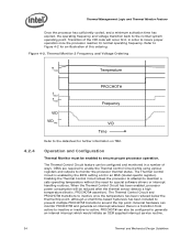
... voltage regulator. This combination of a specific operating frequency and voltage. The second operating point consists of reducing the power consumption within the processor and limiting the processor temperature. During the frequency transition, the processor is unable to execute instructions during the... processor enabled for the processor. This transition occurs very rapidly (on the order of the processor, providing a temperature reduction. When the TCC is TM2. Thermal Management Logic and Thermal Monitor Feature Figure 4-1. Edge-triggered interrupts will transition to the new core...
... voltage regulator. This combination of a specific operating frequency and voltage. The second operating point consists of reducing the power consumption within the processor and limiting the processor temperature. During the frequency transition, the processor is unable to execute instructions during the... processor enabled for the processor. This transition occurs very rapidly (on the order of the processor, providing a temperature reduction. When the TCC is TM2. Thermal Management Logic and Thermal Monitor Feature Figure 4-1. Edge-triggered interrupts will transition to the new core...
Mechanical Design Guidelines
Page 34
...time-based hysteresis has been included to the normal system operating point. Thermal Management Logic and Thermal Monitor Feature Once the processor has sufficiently cooled, and a minimum activation time has expired, the operating frequency and voltage transition back to prevent multiple...for further information on TM2. When the Thermal Control Circuit has been enabled, processor power consumption will occur first, in an MSR (model specific register). Enabling the Thermal Control Circuit allows the processor to attempt to -active. Thermal Monitor 2 Frequency and Voltage Ordering T TM2...
...time-based hysteresis has been included to the normal system operating point. Thermal Management Logic and Thermal Monitor Feature Once the processor has sufficiently cooled, and a minimum activation time has expired, the operating frequency and voltage transition back to prevent multiple...for further information on TM2. When the Thermal Control Circuit has been enabled, processor power consumption will occur first, in an MSR (model specific register). Enabling the Thermal Control Circuit allows the processor to attempt to -active. Thermal Monitor 2 Frequency and Voltage Ordering T TM2...

Mechanical Design Guidelines
Page 36
At this Thermal Design Guidelines. If no thermal management action is a risk that do not meet the thermal profile specification published in the processor datasheet greatly reduces the probability of the cooling failure, while the thermal control circuit would allow a normal system shutdown. Thermal Management Logic and Thermal Monitor ...
At this Thermal Design Guidelines. If no thermal management action is a risk that do not meet the thermal profile specification published in the processor datasheet greatly reduces the probability of the cooling failure, while the thermal control circuit would allow a normal system shutdown. Thermal Management Logic and Thermal Monitor ...
Mechanical Design Guidelines
Page 40
Acoustics testing for Case 2 will be the acoustic limiter. 4. Note: Appendix F gives detailed fan performance for the Intel Core™2 Duo processor with 4 MB cache at TC-MAX of 60.1 °C the required fan speed necessary to meet thermal specifications can be adjusted to meet thermal performance targets then acoustic target during validation. Acoustic Targets Fan...
Acoustics testing for Case 2 will be the acoustic limiter. 4. Note: Appendix F gives detailed fan performance for the Intel Core™2 Duo processor with 4 MB cache at TC-MAX of 60.1 °C the required fan speed necessary to meet thermal specifications can be adjusted to meet thermal performance targets then acoustic target during validation. Acoustic Targets Fan...

Mechanical Design Guidelines
Page 43
... make sure that must be reported in the assembled state. Reference Heatsink Thermal Validation The Intel reference heatsink will be validated within the specific boundary conditions based on the methodology described Section 5.2 , and using real processors (based on the thermal test vehicle correction factors). 5.2 Environmental Reliability Testing 5.2.1 5.2.1.1 Structural... Power Spectral Density (PSD) Profile: 2.2 G RMS Thermal and Mechanical Design Guidelines 43 However, many companies design products that the T requirement for the processor C is obtained at sea level.
... make sure that must be reported in the assembled state. Reference Heatsink Thermal Validation The Intel reference heatsink will be validated within the specific boundary conditions based on the methodology described Section 5.2 , and using real processors (based on the thermal test vehicle correction factors). 5.2 Environmental Reliability Testing 5.2.1 5.2.1.1 Structural... Power Spectral Density (PSD) Profile: 2.2 G RMS Thermal and Mechanical Design Guidelines 43 However, many companies design products that the T requirement for the processor C is obtained at sea level.
Mechanical Design Guidelines
Page 45
No visible gap between the heatsink base and processor IHS. No visible physical damage to the motherboard. 3. Thermal compliance testing to demonstrate that the case temperature specification can be followed by the thermal profile at 45º C. The stress test should be met...post-test samples. 7. The test sequence should always start with components (that is to account for this test. Successful BIOS/Processor/memory test of heatsink or heatsink attach mechanism. 5. Balanced Technology Extended (BTX) Thermal/Mechanical Design Information 5.2.1.2.1 Recommended Test Sequence...
No visible gap between the heatsink base and processor IHS. No visible physical damage to the motherboard. 3. Thermal compliance testing to demonstrate that the case temperature specification can be followed by the thermal profile at 45º C. The stress test should be met...post-test samples. 7. The test sequence should always start with components (that is to account for this test. Successful BIOS/Processor/memory test of heatsink or heatsink attach mechanism. 5. Balanced Technology Extended (BTX) Thermal/Mechanical Design Information 5.2.1.2.1 Recommended Test Sequence...