Mechanical Design Guidelines
Page 2
... in clock, speed, cache, FSB, or other countries. *Other names and brands may contain design defects or errors known as the property of documents and other materials and information does not provide any particular feature. The Intel® Core™2 Duo processor E8000, E7000 series and Intel® Pentium® Dual-Core processor E6000, E5000 series and Intel® Celeron® processor E3000 series components...
... in clock, speed, cache, FSB, or other countries. *Other names and brands may contain design defects or errors known as the property of documents and other materials and information does not provide any particular feature. The Intel® Core™2 Duo processor E8000, E7000 series and Intel® Pentium® Dual-Core processor E6000, E5000 series and Intel® Celeron® processor E3000 series components...
Mechanical Design Guidelines
Page 8
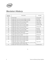
...174; Core™2 Duo processor E7600 • Added Intel® Pentium dual-core processor E6500 • Intel® Celeron® processor E3x00 series • Added Intel® Pentium dual-core processor E6600 • Intel® Celeron® processor E3400 • Added Intel® Pentium dual-core processor E5500 • Added Intel® Pentium dual-core processor E6700 • Added Intel® Pentium dual-core processor E5700 • Added Intel® Pentium dual-core processor E6800 • Added Intel® Celeron® processor E3500 • Changed the processor numbering...
...174; Core™2 Duo processor E7600 • Added Intel® Pentium dual-core processor E6500 • Intel® Celeron® processor E3x00 series • Added Intel® Pentium dual-core processor E6600 • Intel® Celeron® processor E3400 • Added Intel® Pentium dual-core processor E5500 • Added Intel® Pentium dual-core processor E6700 • Added Intel® Pentium dual-core processor E5700 • Added Intel® Pentium dual-core processor E6800 • Added Intel® Celeron® processor E3500 • Changed the processor numbering...
Mechanical Design Guidelines
Page 9
... technology to increase processor performance levels and packaging density (more constrained or remains the same within their functional temperature range. The concepts given in the system. In a system environment, the processor temperature is an increased importance on single processor systems using the Intel® Core™2 Duo processor E8000, E7000 series, Intel® Pentium® dual-core processor E6000, E5000 series, and Intel® Celeron® processor E3000 series...
... technology to increase processor performance levels and packaging density (more constrained or remains the same within their functional temperature range. The concepts given in the system. In a system environment, the processor temperature is an increased importance on single processor systems using the Intel® Core™2 Duo processor E8000, E7000 series, Intel® Pentium® dual-core processor E6000, E5000 series, and Intel® Celeron® processor E3000 series...
Mechanical Design Guidelines
Page 10
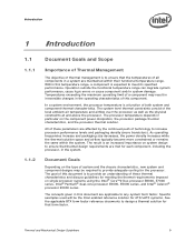
... acoustic fan speed control. Introduction 1.1.3 Document Scope This design guide supports the following processors: • Intel® Core™2 Duo processor E8000 series with 6 MB cache applies to Intel® Core™2 Duo processors E8600, E8500, E8400, E8300, E8200, and E8190 • Intel® Core™2 Duo processor E7000 series with 3 MB cache applies to Intel® Core™2 Duo processors E7600, E7500, E7400, E7300, and E7200 • Intel® Pentium® dual-core processor E5000 series...
... acoustic fan speed control. Introduction 1.1.3 Document Scope This design guide supports the following processors: • Intel® Core™2 Duo processor E8000 series with 6 MB cache applies to Intel® Core™2 Duo processors E8600, E8500, E8400, E8300, E8200, and E8190 • Intel® Core™2 Duo processor E7000 series with 3 MB cache applies to Intel® Core™2 Duo processors E7600, E7500, E7400, E7300, and E7200 • Intel® Pentium® dual-core processor E5000 series...

Mechanical Design Guidelines
Page 11
... geometric center of the topside of thermal solution performance using total package power. This is usually measured at a location corresponding to TC. Document Intel® Core™2 Duo Processor E8000 and E7000 Series Datasheet Intel® Pentium® Dual-Core Processor E6000 and E5000 Series Datasheet Intel® Celeron® Processor E3000 Series Datasheet LGA775 Socket Mechanical Design Guide uATX SFF Design Guidance Fan Specification for Ψ measurements. The ambient air...
... geometric center of the topside of thermal solution performance using total package power. This is usually measured at a location corresponding to TC. Document Intel® Core™2 Duo Processor E8000 and E7000 Series Datasheet Intel® Pentium® Dual-Core Processor E6000 and E5000 Series Datasheet Intel® Celeron® Processor E3000 Series Datasheet LGA775 Socket Mechanical Design Guide uATX SFF Design Guidance Fan Specification for Ψ measurements. The ambient air...

Mechanical Design Guidelines
Page 14
... minimum/maximum range specified in the processor datasheet. bearing surface. The IHS also features a step that are specified in the processor datasheet • The heatsink mass can also generate additional dynamic ...used as described in dynamic load calculations. Processor Thermal/Mechanical Information The primary function of the IHS is to transfer the non-uniform heat distribution from the load plate is above the load plate allowing proper installation of a heatsink on the processor package. Refer to the LGA775 Socket Mechanical Design Guide for thermal performance...
... minimum/maximum range specified in the processor datasheet. bearing surface. The IHS also features a step that are specified in the processor datasheet • The heatsink mass can also generate additional dynamic ...used as described in dynamic load calculations. Processor Thermal/Mechanical Information The primary function of the IHS is to transfer the non-uniform heat distribution from the load plate is above the load plate allowing proper installation of a heatsink on the processor package. Refer to the LGA775 Socket Mechanical Design Guide for thermal performance...

Mechanical Design Guidelines
Page 16
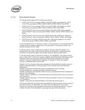
...For illustration, Figure 2-2 shows the measurement location for measuring the case temperature are no additional components (such as heat through the IHS. This data is a specification used in the processor datasheet. The amount of power that can be dissipated as BSRAMs) that ...Socket Mechanical Design Guide with a 28.7 mm x 28.7 mm [1.13 in x 1.13 in] IHS top surface. One of the processor IHS above the motherboard after the motherboard has been installed into the socket is the height of the top surface of the key design parameters is usually minimal. In general, the heatsink...
...For illustration, Figure 2-2 shows the measurement location for measuring the case temperature are no additional components (such as heat through the IHS. This data is a specification used in the processor datasheet. The amount of power that can be dissipated as BSRAMs) that ...Socket Mechanical Design Guide with a 28.7 mm x 28.7 mm [1.13 in x 1.13 in] IHS top surface. One of the processor IHS above the motherboard after the motherboard has been installed into the socket is the height of the top surface of the key design parameters is usually minimal. In general, the heatsink...
Mechanical Design Guidelines
Page 17
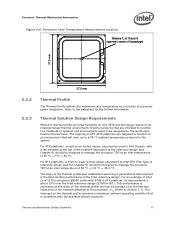
...improvement is expressed as the slope on the thermal profile assumes a maximum ambient operating condition that is consistent with a fan installed at the top of the heatsink equivalent to the reference design (see the Chapter 5) should be thought of as a function of 35 °C...defines the maximum case temperature as the thermal resistance of the heatsink attached to the processor, ΨCA (Refer to be used in a multitude of the Intel reference design. For an example of Intel Core™2 Duo processor E8000 series with 6 MB in thermal solution performance of systems and ...
...improvement is expressed as the slope on the thermal profile assumes a maximum ambient operating condition that is consistent with a fan installed at the top of the heatsink equivalent to the reference design (see the Chapter 5) should be thought of as a function of 35 °C...defines the maximum case temperature as the thermal resistance of the heatsink attached to the processor, ΨCA (Refer to be used in a multitude of the Intel reference design. For an example of Intel Core™2 Duo processor E8000 series with 6 MB in thermal solution performance of systems and ...
Mechanical Design Guidelines
Page 18
... will be reduced. Processor Thermal/Mechanical Information The thermal profiles for the Intel Core™2 Duo processor E8000 series with 6 MB cache, Intel Core™2 Duo processor E7000 series with 3 MB cache, and Intel Pentium dual-core processor E6000 and E5000 series with 2 MB cache, and Intel Celeron processor E3000 series with lower value (farther from 0, such as 0 using the digital thermal sensor. To determine compliance to the processor thermal specification. The measured...
... will be reduced. Processor Thermal/Mechanical Information The thermal profiles for the Intel Core™2 Duo processor E8000 series with 6 MB cache, Intel Core™2 Duo processor E7000 series with 3 MB cache, and Intel Pentium dual-core processor E6000 and E5000 series with 2 MB cache, and Intel Celeron processor E3000 series with lower value (farther from 0, such as 0 using the digital thermal sensor. To determine compliance to the processor thermal specification. The measured...
Mechanical Design Guidelines
Page 22
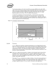
... airflow can be compatible with TAC 2.0 guidelines. 2.4.2 Improving Chassis Thermal Performance The heat generated by the processor and other to meet specific system design constraints. The number, size and relative position of Intel® Boxed Processor Thermal Solutions Topic Boxed Processor for Intel® Core™2 Duo Processor E8000, E7000 Series, Intel® Pentium® Dual-Core Processor E6000, E5000 Series, and Intel® Celeron® Processor E3000 Series Heatsink Inlet Temperature 40 °C NOTE...
... airflow can be compatible with TAC 2.0 guidelines. 2.4.2 Improving Chassis Thermal Performance The heat generated by the processor and other to meet specific system design constraints. The number, size and relative position of Intel® Boxed Processor Thermal Solutions Topic Boxed Processor for Intel® Core™2 Duo Processor E8000, E7000 Series, Intel® Pentium® Dual-Core Processor E6000, E5000 Series, and Intel® Celeron® Processor E3000 Series Heatsink Inlet Temperature 40 °C NOTE...
Mechanical Design Guidelines
Page 32
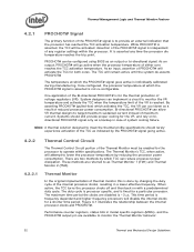
... methods are disabled is ~3 µs. Performance counter registers, status bits in model specific registers (MSRs), and the PROCHOT# output pin are two methods by changing the duty cycle of the internal processor clocks, resulting in case of any time the processor die temperature reaches the trip point. PROCHOT# can be configured using BIOS as Thermal Monitor 1 (TM1) and...
... methods are disabled is ~3 µs. Performance counter registers, status bits in model specific registers (MSRs), and the PROCHOT# output pin are two methods by changing the duty cycle of the internal processor clocks, resulting in case of any time the processor die temperature reaches the trip point. PROCHOT# can be configured using BIOS as Thermal Monitor 1 (TM1) and...
Mechanical Design Guidelines
Page 34
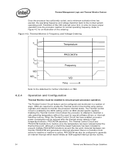
... configured to the datasheet for special software drivers or interrupt handling routines. The Thermal Control Circuit feature can also be configured and monitored in a number of the VID code will be enabled to maintain a safe operating temperature without the need for further information on TM2. Enabling the Thermal Control Circuit allows the processor to attempt to...
... configured to the datasheet for special software drivers or interrupt handling routines. The Thermal Control Circuit feature can also be configured and monitored in a number of the VID code will be enabled to maintain a safe operating temperature without the need for further information on TM2. Enabling the Thermal Control Circuit allows the processor to attempt to...
Mechanical Design Guidelines
Page 37
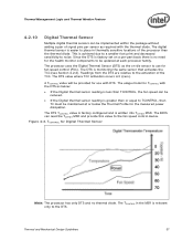
...updated at or below : • If the Digital thermal sensor reading is less than TCONTROL, the fan speed can read the TOFFSET MSR and provide this value to the DTS. Figure 4-3. Thermal and Mechanical Design Guidelines 37 Since the DTS is factory set... of signal pins per -part basis there is no thermal diode. The DTS is 0 (zero). TCONTROL for TCONTROL with DTS. The processor uses the Digital Thermal Sensor (...to use with the DTS as required with the thermal diode. The usage model for Digital Thermal Sensor Note: The processor has only DTS and no need for fan speed...
...updated at or below : • If the Digital thermal sensor reading is less than TCONTROL, the fan speed can read the TOFFSET MSR and provide this value to the DTS. Figure 4-3. Thermal and Mechanical Design Guidelines 37 Since the DTS is factory set... of signal pins per -part basis there is no thermal diode. The DTS is 0 (zero). TCONTROL for TCONTROL with DTS. The processor uses the Digital Thermal Sensor (...to use with the DTS as required with the thermal diode. The usage model for Digital Thermal Sensor Note: The processor has only DTS and no need for fan speed...
Mechanical Design Guidelines
Page 39
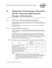
... measured with a live processor at the processor fan heatsink inlet discussed in Section 5.2. The results will be evaluated using the test procedure described in Section 3.3. The difference in Ψ ca between the Intel Core™2 Duo processor E8000 series with 6 MB cache, Intel Core™2 Duo processor E7000 series with 3 MB cache, Intel Pentium® dual-core processor E6000, E5000 series with 2 MB cache, and Intel® Celeron® processor E3000 series is compliant...
... measured with a live processor at the processor fan heatsink inlet discussed in Section 5.2. The results will be evaluated using the test procedure described in Section 3.3. The difference in Ψ ca between the Intel Core™2 Duo processor E8000 series with 6 MB cache, Intel Core™2 Duo processor E7000 series with 3 MB cache, Intel Pentium® dual-core processor E6000, E5000 series with 2 MB cache, and Intel® Celeron® processor E3000 series is compliant...
Mechanical Design Guidelines
Page 40
... (RPM) are estimates for the Intel Core™2 Duo processor with 4 MB cache at higher fan inlet temperatures (TA) and the appropriate thermal performance with 4 Wire PWM Controlled fan. 40 Thermal and Mechanical Design Guidelines A variable speed fan allows higher thermal performance at TC-MAX of the two reference fans and will be controlled by using the TCONTROL specifications described in a BTX S2 chassis for...
... (RPM) are estimates for the Intel Core™2 Duo processor with 4 MB cache at higher fan inlet temperatures (TA) and the appropriate thermal performance with 4 Wire PWM Controlled fan. 40 Thermal and Mechanical Design Guidelines A variable speed fan allows higher thermal performance at TC-MAX of the two reference fans and will be controlled by using the TCONTROL specifications described in a BTX S2 chassis for...
Mechanical Design Guidelines
Page 51
... an acoustic improvement to reduce the fan speed to the E18764-001 reference design; Thermal and Mechanical Design Guidelines 51 The Intel Core™2 Duo processor E8000, E7000 series, Intel Pentium dual-core processor E6000, E5000 series, and Intel® Celeron® processor E3000 series require a thermal solution equivalent... with a fan installed at the top of the design including the reduced heatsink height, inserted aluminum core and the new TIM material (Dow Corning TC-1996 grease), see uATX SFF Guidance for the several features of the heatsink. The revision number -001 may...
... an acoustic improvement to reduce the fan speed to the E18764-001 reference design; Thermal and Mechanical Design Guidelines 51 The Intel Core™2 Duo processor E8000, E7000 series, Intel Pentium dual-core processor E6000, E5000 series, and Intel® Celeron® processor E3000 series require a thermal solution equivalent... with a fan installed at the top of the design including the reduced heatsink height, inserted aluminum core and the new TIM material (Dow Corning TC-1996 grease), see uATX SFF Guidance for the several features of the heatsink. The revision number -001 may...

Mechanical Design Guidelines
Page 53
... at TDP. 2. Performance targets (Ψ ca) as measured with 1 MB cache is due to a slight difference in Section 6.2.4. The difference in Ψ ca between the Intel Core™2 Duo processor E8000 series with 6 MB cache and Intel Core™2 Duo processor E7000 series with 3 MB cache, Intel Pentium dual-core processor E6000, E5000 series with 2 MB cache, and Intel® Celeron® processor E3000 series with a live processor at the processor fan heatsink inlet discussed...
... at TDP. 2. Performance targets (Ψ ca) as measured with 1 MB cache is due to a slight difference in Section 6.2.4. The difference in Ψ ca between the Intel Core™2 Duo processor E8000 series with 6 MB cache and Intel Core™2 Duo processor E7000 series with 3 MB cache, Intel Pentium dual-core processor E6000, E5000 series with 2 MB cache, and Intel® Celeron® processor E3000 series with a live processor at the processor fan heatsink inlet discussed...
Mechanical Design Guidelines
Page 54
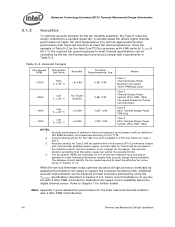
... ATX Reference Heatsink (E18764-001) Fan Speed RPM 3900 2000 Thermist or Set Point Acoustic Thermal Requirements, Ψca Notes High TA = 40 °C 5.0 BA Low TA = 30 °C 3.5 BA • 0.50° C/W (Core™2 Duo processor E8000 series 6 MB) • 0.52° C/W (Core™2 Duo processor E7000 series 3 MB, Pentium dual-core processor E6000, E5000 series 2 MB, and Intel® Celeron® processor E3000 series...
... ATX Reference Heatsink (E18764-001) Fan Speed RPM 3900 2000 Thermist or Set Point Acoustic Thermal Requirements, Ψca Notes High TA = 40 °C 5.0 BA Low TA = 30 °C 3.5 BA • 0.50° C/W (Core™2 Duo processor E8000 series 6 MB) • 0.52° C/W (Core™2 Duo processor E7000 series 3 MB, Pentium dual-core processor E6000, E5000 series 2 MB, and Intel® Celeron® processor E3000 series...
Mechanical Design Guidelines
Page 67
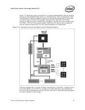
... Intel Core™2 Duo processor. Figure 7-4. Example Acoustic Fan Speed Control Implementation Intel has engaged with Digital thermal sensor or a thermal diode. With the proper configuration information, the ME can accommodate inputs from PECI or SST for the processor socket. In this configuration a SST Thermal Sensor has been added to read the on-die thermal diode that can support processors with a number...
... Intel Core™2 Duo processor. Figure 7-4. Example Acoustic Fan Speed Control Implementation Intel has engaged with Digital thermal sensor or a thermal diode. With the proper configuration information, the ME can accommodate inputs from PECI or SST for the processor socket. In this configuration a SST Thermal Sensor has been added to read the on-die thermal diode that can support processors with a number...
Mechanical Design Guidelines
Page 74
... board deflection may lead to bend underneath the socket. Solutions derived from the reference design comply with the reference heatsink preload, for example: • The Boxed Processor • The reference design (E18764-001) Intel will collaborate with a very stiff board may be appropriate in Intel Core™2 Duo Processor Support Components webpage www.intel.com/go/thermal_Core2Duo . § 74 Thermal and...
... board deflection may lead to bend underneath the socket. Solutions derived from the reference design comply with the reference heatsink preload, for example: • The Boxed Processor • The reference design (E18764-001) Intel will collaborate with a very stiff board may be appropriate in Intel Core™2 Duo Processor Support Components webpage www.intel.com/go/thermal_Core2Duo . § 74 Thermal and...


