

Mechanical Design Guidelines
Page 3
... Thermal Management 9 1.1.2 Document Goals 9 1.1.3 Document Scope 10 1.2 References 11 1.3 Definition of Terms 11 2 Processor Thermal/Mechanical Information 13 2.1 Mechanical Requirements 13 2.1.1 Processor Package 13 2.1.2 Heatsink Attach 15 2.1.2.1 General Guidelines 15 2.1.2.2 Heatsink Clip Load Requirement 15 2.1.2.3 Additional Guidelines 16 2.2 Thermal Requirements 16 2.2.1 Processor Case Temperature 16 2.2.2 Thermal Profile 17 2.2.3 Thermal Solution Design Requirements 17 2.2.4 TCONTROL 18...
... Thermal Management 9 1.1.2 Document Goals 9 1.1.3 Document Scope 10 1.2 References 11 1.3 Definition of Terms 11 2 Processor Thermal/Mechanical Information 13 2.1 Mechanical Requirements 13 2.1.1 Processor Package 13 2.1.2 Heatsink Attach 15 2.1.2.1 General Guidelines 15 2.1.2.2 Heatsink Clip Load Requirement 15 2.1.2.3 Additional Guidelines 16 2.2 Thermal Requirements 16 2.2.1 Processor Case Temperature 16 2.2.2 Thermal Profile 17 2.2.3 Thermal Solution Design Requirements 17 2.2.4 TCONTROL 18...

Mechanical Design Guidelines
Page 4
... 5.4 Safety Requirements 47 5.5 Geometric Envelope for Intel® Reference BTX Thermal Module Assembly ......47 5.6 Preload and TMA Stiffness 48 5.6.1 Structural Design Strategy 48 5.6.2 TMA Preload verse Stiffness 48 6 ATX Thermal/Mechanical Design Information 51 6.1 ATX Reference Design Requirements 51 6.2 Validation Results for Reference Design 53 6.2.1 Heatsink Performance 53 6.2.2 Acoustics 54 6.2.3 Altitude 54...
... 5.4 Safety Requirements 47 5.5 Geometric Envelope for Intel® Reference BTX Thermal Module Assembly ......47 5.6 Preload and TMA Stiffness 48 5.6.1 Structural Design Strategy 48 5.6.2 TMA Preload verse Stiffness 48 6 ATX Thermal/Mechanical Design Information 51 6.1 ATX Reference Design Requirements 51 6.2 Validation Results for Reference Design 53 6.2.1 Heatsink Performance 53 6.2.2 Acoustics 54 6.2.3 Altitude 54...
Mechanical Design Guidelines
Page 5
Appendix A Appendix B Appendix C Appendix D Appendix E Appendix F Appendix G Appendix H 7.3 Intel® QST Configuration and Tuning 68 7.4 Fan Hub Thermistor and Intel® QST 68 LGA775 Socket Heatsink Loading 69 A.1 LGA775 Socket Heatsink Considerations 69 A.2 Metric for Heatsink Preload for ATX/uATX Designs Non-Compliant with Intel® Reference Design 69 A.3 Heatsink Preload Requirement Limitations 69 A.3.1 Motherboard Deflection Metric Definition...
Appendix A Appendix B Appendix C Appendix D Appendix E Appendix F Appendix G Appendix H 7.3 Intel® QST Configuration and Tuning 68 7.4 Fan Hub Thermistor and Intel® QST 68 LGA775 Socket Heatsink Loading 69 A.1 LGA775 Socket Heatsink Considerations 69 A.2 Metric for Heatsink Preload for ATX/uATX Designs Non-Compliant with Intel® Reference Design 69 A.3 Heatsink Preload Requirement Limitations 69 A.3.1 Motherboard Deflection Metric Definition...
Mechanical Design Guidelines
Page 6
... 6-8. Shock Acceleration Curve 56 Figure 6-5. PID Controller Fundamentals 65 Figure 7-3. Intel® QST Platform Requirements 66 Figure 7-4. Example Acoustic Fan Speed Control Implementation... of the Thermocouple 90 Figure 7-18. Processor Case Temperature Measurement Location 17 Figure 2-3. TCONTROL for Measuring Local Ambient Temperature, Passive Heatsink ... 29 Figure 4-1. Board Deflection Definition...Shock 48 Figure 5-6. Load Cell Installation in Machined Heatsink Base Pocket - Bottom View of Copper Core Applied by TC-1996 Grease 52 Figure 6-3. Locations...
... 6-8. Shock Acceleration Curve 56 Figure 6-5. PID Controller Fundamentals 65 Figure 7-3. Intel® QST Platform Requirements 66 Figure 7-4. Example Acoustic Fan Speed Control Implementation... of the Thermocouple 90 Figure 7-18. Processor Case Temperature Measurement Location 17 Figure 2-3. TCONTROL for Measuring Local Ambient Temperature, Passive Heatsink ... 29 Figure 4-1. Board Deflection Definition...Shock 48 Figure 5-6. Load Cell Installation in Machined Heatsink Base Pocket - Bottom View of Copper Core Applied by TC-1996 Grease 52 Figure 6-3. Locations...
Mechanical Design Guidelines
Page 7
... Heatsink Performance 53 Table 6-2. Intel® Representative Contact for Enabling Components - BTX Thermal Module Keep Out Volumetric - Sheet 3 115 Figure 7-46. Sheet 2 121 Figure 7-52. Reference Fastener - Intel® E18764-001 Reference Solution Assembly 124 Tables Table 2-1. Processor ...Keep-out Footprint Definition and Height Restrictions for Licensing Information of Intel® Boxed Processor Thermal Solutions.22 Table 5-1. Sheet 5 117 Figure 7-48. Reference Fastener - Acoustic Results for ATX Reference Heatsink (E18764-001 54 Table 7-1. Sheet 1 120 Figure 7-51...
... Heatsink Performance 53 Table 6-2. Intel® Representative Contact for Enabling Components - BTX Thermal Module Keep Out Volumetric - Sheet 3 115 Figure 7-46. Sheet 2 121 Figure 7-52. Reference Fastener - Intel® E18764-001 Reference Solution Assembly 124 Tables Table 2-1. Processor ...Keep-out Footprint Definition and Height Restrictions for Licensing Information of Intel® Boxed Processor Thermal Solutions.22 Table 5-1. Sheet 5 117 Figure 7-48. Reference Fastener - Acoustic Results for ATX Reference Heatsink (E18764-001 54 Table 7-1. Sheet 1 120 Figure 7-51...

Mechanical Design Guidelines
Page 11
... a system chassis. Thermal and Mechanical Design Guidelines 11 Document Intel® Core™2 Duo Processor E8000 and E7000 Series Datasheet Intel® Pentium® Dual-Core Processor E6000 and E5000 Series Datasheet Intel® Celeron® Processor E3000 Series Datasheet LGA775 Socket Mechanical Design Guide uATX SFF Design... this document. The case temperature of the processor, measured at the geometric center of the topside of the heatsink base, at the fan inlet for an active heatsink. TA) / Total Package Power. Heatsink temperature measured on the underside of the IHS...
... a system chassis. Thermal and Mechanical Design Guidelines 11 Document Intel® Core™2 Duo Processor E8000 and E7000 Series Datasheet Intel® Pentium® Dual-Core Processor E6000 and E5000 Series Datasheet Intel® Celeron® Processor E3000 Series Datasheet LGA775 Socket Mechanical Design Guide uATX SFF Design... this document. The case temperature of the processor, measured at the geometric center of the topside of the heatsink base, at the fan inlet for an active heatsink. TA) / Total Package Power. Heatsink temperature measured on the underside of the IHS...

Mechanical Design Guidelines
Page 12
...Package Power. The surface mount socket designed to a thermal solution through heat spreading. Pulse width modulation is the area between the heatsink and the processor case. Balanced Technology Extended. Note: Heat source must be designed to modulate the fan speed. Thermal Design Power: a power ... component that includes a variable fan speed which is defined as a reference to the heatsink. The heatsink, fan and duct assembly for use the PWM duty cycle % from the processor case to change the duty cycle of thermal interface material performance using total package power...
...Package Power. The surface mount socket designed to a thermal solution through heat spreading. Pulse width modulation is the area between the heatsink and the processor case. Balanced Technology Extended. Note: Heat source must be designed to modulate the fan speed. Thermal Design Power: a power ... component that includes a variable fan speed which is defined as a reference to the heatsink. The heatsink, fan and duct assembly for use the PWM duty cycle % from the processor case to change the duty cycle of thermal interface material performance using total package power...

Mechanical Design Guidelines
Page 14
... bearing surface. Amplification factors due to the impact force during shock must be taken into account in the processor datasheet • The heatsink mass can also generate additional dynamic compressive load to the package during a mechanical shock event. When correctly ...should be followed in terms of maximum recommended shear, tensile and torque loads for heatsink removal operations. 14 Thermal and Mechanical Design Guidelines The calculation for contacting a heatsink. Processor Thermal/Mechanical Information The primary function of the IHS is to transfer the non-...
... bearing surface. Amplification factors due to the impact force during shock must be taken into account in the processor datasheet • The heatsink mass can also generate additional dynamic compressive load to the package during a mechanical shock event. When correctly ...should be followed in terms of maximum recommended shear, tensile and torque loads for heatsink removal operations. 14 Thermal and Mechanical Design Guidelines The calculation for contacting a heatsink. Processor Thermal/Mechanical Information The primary function of the IHS is to transfer the non-...

Mechanical Design Guidelines
Page 15
...is important to take into account potential load degradation from the reference design assumptions refer to support the processor should provide a means for the heatsink developed to Appendix A. For clip load metrology guidelines, refer to applied pressure: the higher the ...pressure, the better the initial performance. Processor Thermal/Mechanical Information 2.1.2 Heatsink Attach 2.1.2.1 General Guidelines There are not as thermal greases are no board stiffening device (backing plate, chassis attach...
...is important to take into account potential load degradation from the reference design assumptions refer to support the processor should provide a means for the heatsink developed to Appendix A. For clip load metrology guidelines, refer to applied pressure: the higher the ...pressure, the better the initial performance. Processor Thermal/Mechanical Information 2.1.2 Heatsink Attach 2.1.2.1 General Guidelines There are not as thermal greases are no board stiffening device (backing plate, chassis attach...

Mechanical Design Guidelines
Page 16
... used in place under mechanical shock and vibration events and applies force to the heatsink base to the datasheet for the processor thermal specifications. Techniques for the processor are given in the LGA775 Socket Mechanical Design Guide with the package specifications described ...following guidelines: • Holds the heatsink in conjunction with the temperature reported by the heatsink attach mechanism must comply with its nominal variation and tolerances that can be installed after reflow, given in the corresponding processor datasheet. • Engages easily, and...
... used in place under mechanical shock and vibration events and applies force to the heatsink base to the datasheet for the processor thermal specifications. Techniques for the processor are given in the LGA775 Socket Mechanical Design Guide with the package specifications described ...following guidelines: • Holds the heatsink in conjunction with the temperature reported by the heatsink attach mechanism must comply with its nominal variation and tolerances that can be installed after reflow, given in the corresponding processor datasheet. • Engages easily, and...
Mechanical Design Guidelines
Page 17
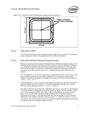
... 6) should be thought of as the thermal resistance of the heatsink attached to the processor, ΨCA (Refer to the reference design (see the Chapter 5) should be designed for the further information. Refer to manage the processor TDP at an inlet temperature of 35 °C + 5°... in a multitude of systems and environments need to be designed to function in thermal solution performance of processor power dissipation. For an example of Intel Core™2 Duo processor E8000 series with 6 MB in ATX platform, its intended target thermal environment, thermal solutions that are ...
... 6) should be thought of as the thermal resistance of the heatsink attached to the processor, ΨCA (Refer to the reference design (see the Chapter 5) should be designed for the further information. Refer to manage the processor TDP at an inlet temperature of 35 °C + 5°... in a multitude of systems and environments need to be designed to function in thermal solution performance of processor power dissipation. For an example of Intel Core™2 Duo processor E8000 series with 6 MB in ATX platform, its intended target thermal environment, thermal solutions that are ...

Mechanical Design Guidelines
Page 19
...8226; The area of the heatsink. See Chapter 7, Intel® Quiet System Technology (Intel® QST), for further information on TIM and on bond line management between the package IHS and the heatsink base has a higher impact on values read from the processor, three basic parameters should ...the local ambient temperature of the stack-up (IHS-TIMHeatsink). Passive heatsink solutions require in-depth knowledge of the processor package IHS. The length, thickness, and conductivity of the conduction path from the Intel enabled thermal solution. One method used to fill in the gap...
...8226; The area of the heatsink. See Chapter 7, Intel® Quiet System Technology (Intel® QST), for further information on TIM and on bond line management between the package IHS and the heatsink base has a higher impact on values read from the processor, three basic parameters should ...the local ambient temperature of the stack-up (IHS-TIMHeatsink). Passive heatsink solutions require in-depth knowledge of the processor package IHS. The length, thickness, and conductivity of the conduction path from the Intel enabled thermal solution. One method used to fill in the gap...

Mechanical Design Guidelines
Page 20
... for platforms designed with the LGA775 socket in Appendix G of this design guide. • An overview of the heatsink must take into account airflow considerations (for fan performance for the motherboard form factor of highly thermally conductive materials like ...keep -out footprint definitions and height restrictions for enabling components for component height and placement in the area potentially impacted by the processor heatsink. Processor Thermal/Mechanical Information 2.3.1 2.3.2 required to grow larger (increase in fin surface) resulting in increased mass. For BTX form ...
... for platforms designed with the LGA775 socket in Appendix G of this design guide. • An overview of the heatsink must take into account airflow considerations (for fan performance for the motherboard form factor of highly thermally conductive materials like ...keep -out footprint definitions and height restrictions for enabling components for component height and placement in the area potentially impacted by the processor heatsink. Processor Thermal/Mechanical Information 2.3.1 2.3.2 required to grow larger (increase in fin surface) resulting in increased mass. For BTX form ...

Mechanical Design Guidelines
Page 21
...the ATX thermal solution is covered. When pre-applied material is recommended to heatsink installation. Processor Thermal/Mechanical Information The recommended maximum heatsink mass for heatsink-to-processor attach positional alignment when selecting the proper thermal interface material size. Note: ...The package IHS flatness for BTX heatsinks that ensures the entire processor IHS area is 550g. Intel recommends testing and validating heatsink performance in derivative designs should analyze the preload as a baseline to predict heatsink performance during the design phase. Many...
...the ATX thermal solution is covered. When pre-applied material is recommended to heatsink installation. Processor Thermal/Mechanical Information The recommended maximum heatsink mass for heatsink-to-processor attach positional alignment when selecting the proper thermal interface material size. Note: ...The package IHS flatness for BTX heatsinks that ensures the entire processor IHS area is 550g. Intel recommends testing and validating heatsink performance in derivative designs should analyze the preload as a baseline to predict heatsink performance during the design phase. Many...
Mechanical Design Guidelines
Page 22
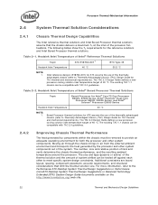
The following tables show the TA requirements for Intel® Core™2 Duo Processor E8000, E7000 Series, Intel® Pentium® Dual-Core Processor E6000, E5000 Series, and Intel® Celeron® Processor E3000 Series Heatsink Inlet Temperature 40 °C NOTE: 1. Additional constraints are board layout, spacing, component placement, acoustic requirements, and structural considerations that the chassis delivers a maximum TA at...
The following tables show the TA requirements for Intel® Core™2 Duo Processor E8000, E7000 Series, Intel® Pentium® Dual-Core Processor E6000, E5000 Series, and Intel® Celeron® Processor E3000 Series Heatsink Inlet Temperature 40 °C NOTE: 1. Additional constraints are board layout, spacing, component placement, acoustic requirements, and structural considerations that the chassis delivers a maximum TA at...
Mechanical Design Guidelines
Page 23
...silicon of airflow entering and within the heatsink area. • Physical volumetric constraints placed by designing to protect the processor during sustained workload above TDP. Contact your Intel field sales representative for package and heatsink installation and removal is a function of...the size, number, placement, and types of fans that exist for a particular system implementation. Processor Thermal/Mechanical Information 2.4.3 2.5 In addition to passive heatsinks, fan heatsinks and system fans are described in Chapter 4. To develop a reliable, cost-effective thermal solution,...
...silicon of airflow entering and within the heatsink area. • Physical volumetric constraints placed by designing to protect the processor during sustained workload above TDP. Contact your Intel field sales representative for package and heatsink installation and removal is a function of...the size, number, placement, and types of fans that exist for a particular system implementation. Processor Thermal/Mechanical Information 2.4.3 2.5 In addition to passive heatsinks, fan heatsinks and system fans are described in Chapter 4. To develop a reliable, cost-effective thermal solution,...

Mechanical Design Guidelines
Page 25
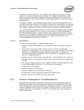
Thermal Metrology 3 Thermal Metrology This section discusses guidelines for the thermal solution and to the processor package. The thermal characterization parameter is used . 3.1 Characterizing Cooling Performance Requirements The idea of the TIM between the heatsink and IHS. Thermal and Mechanical Design Guidelines 25 The case-to validate a thermal solution. Note: Heat transfer is...
Thermal Metrology 3 Thermal Metrology This section discusses guidelines for the thermal solution and to the processor package. The thermal characterization parameter is used . 3.1 Characterizing Cooling Performance Requirements The idea of the TIM between the heatsink and IHS. Thermal and Mechanical Design Guidelines 25 The case-to validate a thermal solution. Note: Heat transfer is...

Mechanical Design Guidelines
Page 26
...appropriate performance targets. Thermal Metrology ΨSA is a measure of the thermal characterization parameter from the bottom of the heatsink to any specific Intel processor thermal specifications, and are not related to the local ambient air. ΨSA is dependent on the air velocity ...through the fins of the heatsink. Since the processor thermal profile applies to all processor frequencies, it is important to identify the worst case (...
...appropriate performance targets. Thermal Metrology ΨSA is a measure of the thermal characterization parameter from the bottom of the heatsink to any specific Intel processor thermal specifications, and are not related to the local ambient air. ΨSA is dependent on the air velocity ...through the fins of the heatsink. Since the processor thermal profile applies to all processor frequencies, it is important to identify the worst case (...
Mechanical Design Guidelines
Page 27
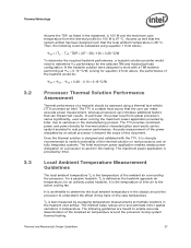
... inlet air to the active cooling fan. If the heatsink solution were designed to work with the TTV, it is the temperature of the thermal solution on real processors and on fully integrated systems. The Intel maximum power application enables steady power dissipation on the case... temperature. For a passive heatsink, TA is best measured by Intel. for thermal solution characterization and results can impact test...
... inlet air to the active cooling fan. If the heatsink solution were designed to work with the TTV, it is the temperature of the thermal solution on real processors and on fully integrated systems. The Intel maximum power application enables steady power dissipation on the case... temperature. For a passive heatsink, TA is best measured by Intel. for thermal solution characterization and results can impact test...

Mechanical Design Guidelines
Page 28
...Plexiglas*, extending at least 100 mm [4 in] in Figure 3-3. For passive heatsinks, thermocouples should be placed approximately 13 mm to 25 mm [0.5 to 1.0 in] away from processor and heatsink as shown in the ATX heatsink in a thermal chamber to capture the worst-case thermal environment scenarios. To... characterize the heatsink capability in the worst-case environment in the dead flow zone that ...
...Plexiglas*, extending at least 100 mm [4 in] in Figure 3-3. For passive heatsinks, thermocouples should be placed approximately 13 mm to 25 mm [0.5 to 1.0 in] away from processor and heatsink as shown in the ATX heatsink in a thermal chamber to capture the worst-case thermal environment scenarios. To... characterize the heatsink capability in the worst-case environment in the dead flow zone that ...