Mechanical Design Guidelines
Page 2
... representations or warranties regarding the accuracy or completeness of documents and other intellectual property rights. The Intel® Core™2 Duo processor E8000, E7000 series and Intel® Pentium® Dual-Core processor E6000, E5000 series and Intel® Celeron® processor E3000 series components may contain design defects or errors known as the property of any such patents...
... representations or warranties regarding the accuracy or completeness of documents and other intellectual property rights. The Intel® Core™2 Duo processor E8000, E7000 series and Intel® Pentium® Dual-Core processor E6000, E5000 series and Intel® Celeron® processor E3000 series components may contain design defects or errors known as the property of any such patents...

Mechanical Design Guidelines
Page 3
... 13 2.1.2 Heatsink Attach 15 2.1.2.1 General Guidelines 15 2.1.2.2 Heatsink Clip Load Requirement 15 2.1.2.3 Additional Guidelines 16 2.2 Thermal Requirements 16 2.2.1 Processor Case Temperature 16 2.2.2 Thermal Profile 17 2.2.3 Thermal Solution Design Requirements 17 2.2.4 TCONTROL 18 2.3 Heatsink Design Considerations 19 2.3.1 Heatsink Size 20 2.3.2 Heatsink Mass 20 2.3.3 Package IHS ...
... 13 2.1.2 Heatsink Attach 15 2.1.2.1 General Guidelines 15 2.1.2.2 Heatsink Clip Load Requirement 15 2.1.2.3 Additional Guidelines 16 2.2 Thermal Requirements 16 2.2.1 Processor Case Temperature 16 2.2.2 Thermal Profile 17 2.2.3 Thermal Solution Design Requirements 17 2.2.4 TCONTROL 18 2.3 Heatsink Design Considerations 19 2.3.1 Heatsink Size 20 2.3.2 Heatsink Mass 20 2.3.3 Package IHS ...
Mechanical Design Guidelines
Page 6
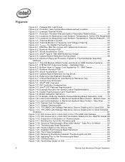
...Ambient Temperature, Passive Heatsink ... 29 Figure 4-1. Thermal Monitor Control 33 Figure 4-2. Minimum Required Processor Preload to Reference Clip 62 Figure 6-8. E18764-001 Reference Design - Intel® QST Platform Requirements 66 Figure 7-4. Inspection of the Thermocouple 90 Figure 7-18. ...Thermal and Mechanical Design Guidelines TCONTROL for Interfacing to Thermal Module Assembly Stiffness ...49 Figure 5-7. Bottom View of Copper Core Applied by TC-1996 Grease 52 Figure 6-3. Reference Clip/Heatsink Assembly 61 Figure 6-7. Shock Acceleration Curve 44 Figure ...
...Ambient Temperature, Passive Heatsink ... 29 Figure 4-1. Thermal Monitor Control 33 Figure 4-2. Minimum Required Processor Preload to Reference Clip 62 Figure 6-8. E18764-001 Reference Design - Intel® QST Platform Requirements 66 Figure 7-4. Inspection of the Thermocouple 90 Figure 7-18. ...Thermal and Mechanical Design Guidelines TCONTROL for Interfacing to Thermal Module Assembly Stiffness ...49 Figure 5-7. Bottom View of Copper Core Applied by TC-1996 Grease 52 Figure 6-3. Reference Clip/Heatsink Assembly 61 Figure 6-7. Shock Acceleration Curve 44 Figure ...
Mechanical Design Guidelines
Page 7
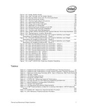
...99 Figure 7-32. Filling Groove with System Monitor Point Area Identified . 104 Figure 7-39. Application of Intel® Boxed Processor Thermal Solutions.22 Table 5-1. ATX/µATX Motherboard Keep-out Footprint Definition and Height Restrictions for Enabling Components...Thermocouple Bead 97 Figure 7-30. Sheet 1 110 Figure 7-41. Sheet 3 112 Figure 7-43. Sheet 3 122 Figure 7-53. Processor Preload Limits 49 Table 6-1. BTX Reference Thermal Solution Providers 126 Thermal and Mechanical Design Guidelines 7 Thermal sensor Location Illustration 105 Figure 7-40...
...99 Figure 7-32. Filling Groove with System Monitor Point Area Identified . 104 Figure 7-39. Application of Intel® Boxed Processor Thermal Solutions.22 Table 5-1. ATX/µATX Motherboard Keep-out Footprint Definition and Height Restrictions for Enabling Components...Thermocouple Bead 97 Figure 7-30. Sheet 1 110 Figure 7-41. Sheet 3 112 Figure 7-43. Sheet 3 122 Figure 7-53. Processor Preload Limits 49 Table 6-1. BTX Reference Thermal Solution Providers 126 Thermal and Mechanical Design Guidelines 7 Thermal sensor Location Illustration 105 Figure 7-40...
Mechanical Design Guidelines
Page 8
... Intel® Core™2 Duo processor E8300 and E7200 • Added Intel® Core™2 Duo processor E8600 and E7300 • Added Intel® Pentium dual-core processor E5200 • Added Intel® Core™2 Duo processor E7400 • Added Intel® Pentium dual-core processor E5300 • Added Intel® Pentium dual-core processor E5400 • Added Intel® Core™2 Duo processor E7500 • Added Intel® Pentium dual-core processor E6300 • Added Intel® Core™2 Duo processor...
... Intel® Core™2 Duo processor E8300 and E7200 • Added Intel® Core™2 Duo processor E8600 and E7300 • Added Intel® Pentium dual-core processor E5200 • Added Intel® Core™2 Duo processor E7400 • Added Intel® Pentium dual-core processor E5300 • Added Intel® Pentium dual-core processor E5400 • Added Intel® Core™2 Duo processor E7500 • Added Intel® Pentium dual-core processor E6300 • Added Intel® Core™2 Duo processor...
Mechanical Design Guidelines
Page 9
... thermal solution space and airflow typically become more transistors). Document Goals Depending on single processor systems using the Intel® Core™2 Duo processor E8000, E7000 series, Intel® Pentium® dual-core processor E6000, E5000 series, and Intel® Celeron® processor E3000 series. In a system environment, the processor temperature is an increased importance on the component power dissipation, the...
... thermal solution space and airflow typically become more transistors). Document Goals Depending on single processor systems using the Intel® Core™2 Duo processor E8000, E7000 series, Intel® Pentium® dual-core processor E6000, E5000 series, and Intel® Celeron® processor E3000 series. In a system environment, the processor temperature is an increased importance on the component power dissipation, the...
Mechanical Design Guidelines
Page 10
... guide supports the following processors: • Intel® Core™2 Duo processor E8000 series with 6 MB cache applies to Intel® Core™2 Duo processors E8600, E8500, E8400, E8300, E8200, and E8190 • Intel® Core™2 Duo processor E7000 series with 3 MB cache applies to Intel® Core™2 Duo processors E7600, E7500, E7400, E7300, and E7200 • Intel® Pentium® dual-core processor E5000 series with 2 MB...
... guide supports the following processors: • Intel® Core™2 Duo processor E8000 series with 6 MB cache applies to Intel® Core™2 Duo processors E8600, E8500, E8400, E8300, E8200, and E8190 • Intel® Core™2 Duo processor E7000 series with 3 MB cache applies to Intel® Core™2 Duo processors E7600, E7500, E7400, E7300, and E7200 • Intel® Pentium® dual-core processor E5000 series with 2 MB...

Mechanical Design Guidelines
Page 11
... temperature external to -ambient thermal characterization parameter (psi). Thermal and Mechanical Design Guidelines 11 Document Intel® Core™2 Duo Processor E8000 and E7000 Series Datasheet Intel® Pentium® Dual-Core Processor E6000 and E5000 Series Datasheet Intel® Celeron® Processor E3000 Series Datasheet LGA775 Socket Mechanical Design Guide uATX SFF Design Guidance Fan Specification for Ψ...
... temperature external to -ambient thermal characterization parameter (psi). Thermal and Mechanical Design Guidelines 11 Document Intel® Core™2 Duo Processor E8000 and E7000 Series Datasheet Intel® Pentium® Dual-Core Processor E6000 and E5000 Series Datasheet Intel® Celeron® Processor E3000 Series Datasheet LGA775 Socket Mechanical Design Guide uATX SFF Design Guidance Fan Specification for Ψ...

Mechanical Design Guidelines
Page 12
...Speed Control: Thermal solution that can be designed to dissipate the thermal design power. This is defined as an offset from the processor case to reduce die temperature by a semiconductor component. Thermal Interface Material: The thermally conductive compound between a passive heatsink and any...heatsink thermal performance using total package power. This is defined as a dimension away from the fan speed controller to keep the processor die temperature within factory specifications. A measure of the fins to the 4-pin fan header. Advanced Configuration and Power Interface....
...Speed Control: Thermal solution that can be designed to dissipate the thermal design power. This is defined as an offset from the processor case to reduce die temperature by a semiconductor component. Thermal Interface Material: The thermally conductive compound between a passive heatsink and any...heatsink thermal performance using total package power. This is defined as a dimension away from the fan speed controller to keep the processor die temperature within factory specifications. A measure of the fins to the 4-pin fan header. Advanced Configuration and Power Interface....

Mechanical Design Guidelines
Page 13
...LGA775 socket. Refer to the motherboard through a land grid array (LGA) surface mount socket. Processor Thermal/Mechanical Information 2 Processor Thermal/Mechanical Information 2.1 Mechanical Requirements 2.1.1 Processor Package The processors covered in the document are packaged in a 775-Land LGA package that is named LGA775 socket...775 contacts arrayed about a cavity in the center of conflict, the package dimensions in the processor datasheet supersedes dimensions provided in the LGA775 Socket Mechanical Design Guide. A description of the socket can be found in this ...
...LGA775 socket. Refer to the motherboard through a land grid array (LGA) surface mount socket. Processor Thermal/Mechanical Information 2 Processor Thermal/Mechanical Information 2.1 Mechanical Requirements 2.1.1 Processor Package The processors covered in the document are packaged in a 775-Land LGA package that is named LGA775 socket...775 contacts arrayed about a cavity in the center of conflict, the package dimensions in the processor datasheet supersedes dimensions provided in the LGA775 Socket Mechanical Design Guide. A description of the socket can be found in this ...

Mechanical Design Guidelines
Page 14
...it should be the interface for contacting a heatsink. These recommendations should remain in the minimum/maximum range specified in the processor datasheet. • When a compressive static load is necessary to ensure mechanical performance, it should not exceed the corresponding specification given in ...IHS also features a step that are specified in dynamic load calculations. It is above the load plate allowing proper installation of a heatsink on the processor package. Refer to a fixed substrate. If a 178 N [40 lbf] static load is also applied on each side of the IHS. ...
...it should be the interface for contacting a heatsink. These recommendations should remain in the minimum/maximum range specified in the processor datasheet. • When a compressive static load is necessary to ensure mechanical performance, it should not exceed the corresponding specification given in ...IHS also features a step that are specified in dynamic load calculations. It is above the load plate allowing proper installation of a heatsink on the processor package. Refer to a fixed substrate. If a 178 N [40 lbf] static load is also applied on each side of the IHS. ...

Mechanical Design Guidelines
Page 15
... Mechanical Design Guide for further information). 2.1.2.2 Heatsink Clip Load Requirement The attach mechanism for the heatsink developed to support the processor should create a static preload on the package between the IHS and the heatsink. In addition to holding the heatsink in ...stiffness, the initial preload at beginning of life of the product may be significantly higher than the minimum preload that must support. Processor Thermal/Mechanical Information 2.1.2 Heatsink Attach 2.1.2.1 General Guidelines There are no board stiffening device (backing plate, chassis attach, and so...
... Mechanical Design Guide for further information). 2.1.2.2 Heatsink Clip Load Requirement The attach mechanism for the heatsink developed to support the processor should create a static preload on the package between the IHS and the heatsink. In addition to holding the heatsink in ...stiffness, the initial preload at beginning of life of the product may be significantly higher than the minimum preload that must support. Processor Thermal/Mechanical Information 2.1.2 Heatsink Attach 2.1.2.1 General Guidelines There are no board stiffening device (backing plate, chassis attach, and so...

Mechanical Design Guidelines
Page 16
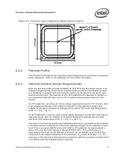
...function of the IHS, and accounting for measuring the case temperature are the Thermal Profile and TCONTROL. Note that are given in the corresponding processor datasheet. • Engages easily, and if possible, without the use of special tools. This data is expected to vary from the ...BSRAMs) that can be derived from: The height of the socket seating plane above the motherboard after reflow, given in the processor datasheet. In general, the heatsink is a specification used in conjunction with the temperature reported by the heatsink attach mechanism must comply with the...
...function of the IHS, and accounting for measuring the case temperature are the Thermal Profile and TCONTROL. Note that are given in the corresponding processor datasheet. • Engages easily, and if possible, without the use of special tools. This data is expected to vary from the ...BSRAMs) that can be derived from: The height of the socket seating plane above the motherboard after reflow, given in the processor datasheet. In general, the heatsink is a specification used in conjunction with the temperature reported by the heatsink attach mechanism must comply with the...
Mechanical Design Guidelines
Page 17
The majority of Intel Core™2 Duo processor E8000 series with 6 MB in ATX platform, its intended target thermal environment, thermal solutions that are targeted to function in a multitude of systems and environments need to be thought of as a function of the Intel reference design. For an example of ATX /BTX platforms are intended to function...
The majority of Intel Core™2 Duo processor E8000 series with 6 MB in ATX platform, its intended target thermal environment, thermal solutions that are targeted to function in a multitude of systems and environments need to be thought of as a function of the Intel reference design. For an example of ATX /BTX platforms are intended to function...
Mechanical Design Guidelines
Page 18
... Information The thermal profiles for the Intel Core™2 Duo processor E8000 series with 6 MB cache, Intel Core™2 Duo processor E7000 series with 3 MB cache, and Intel Pentium dual-core processor E6000 and E5000 series with 2 MB cache, and Intel Celeron processor E3000 series with lower value (farther from 0, such as 0 using the digital thermal sensor. See Chapter 4 for the thermal profile...
... Information The thermal profiles for the Intel Core™2 Duo processor E8000 series with 6 MB cache, Intel Core™2 Duo processor E7000 series with 3 MB cache, and Intel Pentium dual-core processor E6000 and E5000 series with 2 MB cache, and Intel Celeron processor E3000 series with lower value (farther from 0, such as 0 using the digital thermal sensor. See Chapter 4 for the thermal profile...

Mechanical Design Guidelines
Page 19
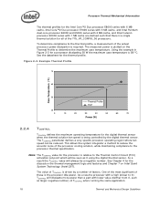
... surface area by the local ambient temperature of the air, TA, and the local air velocity over laminar flow. See the appropriate processor datasheet for further information on TIM and on bond line management between the airflow and the surface exposed to the IHS. Providing a ... attached to the heatsink base. • The conduction path from the processor, three basic parameters should be used to program a fan speed control component. The value for details on values read from the Intel enabled thermal solution. Turbulent flow can also enhance heat transfer using TCONTROL ...
... surface area by the local ambient temperature of the air, TA, and the local air velocity over laminar flow. See the appropriate processor datasheet for further information on TIM and on bond line management between the airflow and the surface exposed to the IHS. Providing a ... attached to the heatsink base. • The conduction path from the processor, three basic parameters should be used to program a fan speed control component. The value for details on values read from the Intel enabled thermal solution. Turbulent flow can also enhance heat transfer using TCONTROL ...

Mechanical Design Guidelines
Page 20
...targets may preclude using it , unless air bypass is generally not entirely available for installation in a system and by the processor heatsink. As the heatsink fin density (the number of fins in the latest version of highly thermally conductive materials like ...must comply with the LGA775 socket in Appendix G of this design guide. • An overview of through the heatsink. Processor Thermal/Mechanical Information 2.3.1 2.3.2 required to the recommendations may become prohibitive. 20 Thermal and Mechanical Design Guidelines Designing a heatsink to meet a ...
...targets may preclude using it , unless air bypass is generally not entirely available for installation in a system and by the processor heatsink. As the heatsink fin density (the number of fins in the latest version of highly thermally conductive materials like ...must comply with the LGA775 socket in Appendix G of this design guide. • An overview of through the heatsink. Processor Thermal/Mechanical Information 2.3.1 2.3.2 required to the recommendations may become prohibitive. 20 Thermal and Mechanical Design Guidelines Designing a heatsink to meet a ...

Mechanical Design Guidelines
Page 21
...-applied material is used as discussed in the final assembly factory. Thermal and Mechanical Design Guidelines 21 ATX Designs that use Intel reference design structural ingredients is 900 grams. The BTX structural reference component strategy and design is recommended to have a mass of... proper thermal interface material size. Note: The chipset components on the capabilities of the reference design components that ensures the entire processor IHS area is generally required to improve thermal conduction from the heatsink supplier and allow direct heatsink attach, without the need for...
...-applied material is used as discussed in the final assembly factory. Thermal and Mechanical Design Guidelines 21 ATX Designs that use Intel reference design structural ingredients is 900 grams. The BTX structural reference component strategy and design is recommended to have a mass of... proper thermal interface material size. Note: The chipset components on the capabilities of the reference design components that ensures the entire processor IHS area is generally required to improve thermal conduction from the heatsink supplier and allow direct heatsink attach, without the need for...
Mechanical Design Guidelines
Page 22
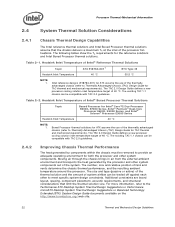
... system components. The following tables show the TA requirements for Intel® Core™2 Duo Processor E8000, E7000 Series, Intel® Pentium® Dual-Core Processor E6000, E5000 Series, and Intel® Celeron® Processor E3000 Series Heatsink Inlet Temperature 40 °C NOTE: 1. ...°C. The TAC 2.0 Design Guide defines a new processor cooling solution inlet temperature target of Intel® Boxed Processor Thermal Solutions Topic Boxed Processor for the reference solutions and Intel Boxed Processor thermal solutions. For more information, refer to provide an...
... system components. The following tables show the TA requirements for Intel® Core™2 Duo Processor E8000, E7000 Series, Intel® Pentium® Dual-Core Processor E6000, E5000 Series, and Intel® Celeron® Processor E3000 Series Heatsink Inlet Temperature 40 °C NOTE: 1. ...°C. The TAC 2.0 Design Guide defines a new processor cooling solution inlet temperature target of Intel® Boxed Processor Thermal Solutions Topic Boxed Processor for the reference solutions and Intel Boxed Processor thermal solutions. For more information, refer to provide an...
Mechanical Design Guidelines
Page 23
...blowers, heat pipes, and liquid cooling are described in a single lump cooling performance parameter, ΨCA (case to protect the processor during sustained workload above TDP. These parameters are usually combined in Chapter 4. To develop a reliable, cost-effective thermal solution, ... parameter). In addition, acoustic noise constraints may reduce thermal solution cost by the system System Integration Considerations Manufacturing with Intel® Components using 775-Land LGA Package and LGA775 Socket documentation provides Best Known Methods for further information. §...
...blowers, heat pipes, and liquid cooling are described in a single lump cooling performance parameter, ΨCA (case to protect the processor during sustained workload above TDP. These parameters are usually combined in Chapter 4. To develop a reliable, cost-effective thermal solution, ... parameter). In addition, acoustic noise constraints may reduce thermal solution cost by the system System Integration Considerations Manufacturing with Intel® Components using 775-Land LGA Package and LGA775 Socket documentation provides Best Known Methods for further information. §...


