Product Specification
Page 5
Contents 1 Product Description 1.1 Power Connector Terminology Change 9 1.2 Overview ...10 1.2.1 Feature Summary 10 1.2.2 Manufacturing Options 11 1.2.3 Board Layout 12 1.2.4 Block Diagram 14 1.3 Online Support ...15 1.4 Processor ...15 1.5 System Memory ...16 1.5.1 Memory Configurations 17 1.6 Intel® 945P Chipset...21 1.6.1 USB ...21 1.6.2 IDE Support 22 1.6.3 Real-Time Clock, CMOS SRAM, and Battery 23 1.7 PCI Express* Connectors 23...
Contents 1 Product Description 1.1 Power Connector Terminology Change 9 1.2 Overview ...10 1.2.1 Feature Summary 10 1.2.2 Manufacturing Options 11 1.2.3 Board Layout 12 1.2.4 Block Diagram 14 1.3 Online Support ...15 1.4 Processor ...15 1.5 System Memory ...16 1.5.1 Memory Configurations 17 1.6 Intel® 945P Chipset...21 1.6.1 USB ...21 1.6.2 IDE Support 22 1.6.3 Real-Time Clock, CMOS SRAM, and Battery 23 1.7 PCI Express* Connectors 23...

Product Specification
Page 7
... 18 6. Thermal Sensors and Fan Connectors 31 14. Detailed System Memory Address Map 40 16. Component-side Connectors 48 18. Processor Heatsink for IEEE 1394a Connectors 55 21. LAN Connector LED States 29 7. Dual Channel (Interleaved) Mode Configuration with Four DIMMs 19...with Two DIMMs 18 5. Back Panel Connectors 47 17. Connection Diagram for Omni-directional Airflow 61 25. I/O Shield Dimensions 58 24. Board Components ...12 2. Single Channel (Asymmetric) Mode Configuration with Three DIMMs 20 9. Location of Pressing the Power Switch 32 8. Power States...
... 18 6. Thermal Sensors and Fan Connectors 31 14. Detailed System Memory Address Map 40 16. Component-side Connectors 48 18. Processor Heatsink for IEEE 1394a Connectors 55 21. LAN Connector LED States 29 7. Dual Channel (Interleaved) Mode Configuration with Four DIMMs 19...with Two DIMMs 18 5. Back Panel Connectors 47 17. Connection Diagram for Omni-directional Airflow 61 25. I/O Shield Dimensions 58 24. Board Components ...12 2. Single Channel (Asymmetric) Mode Configuration with Three DIMMs 20 9. Location of Pressing the Power Switch 32 8. Power States...

Product Specification
Page 8
... ...65 36. Supervisor and User Password Functions 75 41. Port 80h POST Code Ranges 78 44. Intel Desktop Board D945PAW Technical Product Specification 10. PCI Configuration Space Map 43 14. Chassis Intrusion Connector 50 20. Processor Fan Connector 50 22. Processor Core Power Connector 51 25. Safety Regulations ...65 35. Product Certification Markings 68 37. BIOS...
... ...65 36. Supervisor and User Password Functions 75 41. Port 80h POST Code Ranges 78 44. Intel Desktop Board D945PAW Technical Product Specification 10. PCI Configuration Space Map 43 14. Chassis Intrusion Connector 50 20. Processor Fan Connector 50 22. Processor Core Power Connector 51 25. Safety Regulations ...65 35. Product Certification Markings 68 37. BIOS...

Product Specification
Page 9
...Description What This Chapter Contains 1.1 Power Connector Terminology Change 9 1.2 Overview ...10 1.3 Online Support ...15 1.4 Processor ...15 1.5 System Memory ...16 1.6 Intel® 945P Chipset...21 1.7 PCI Express* Connectors 23 1.8 IEEE-1394a Connectors (Optional 24 1.9 Legacy I/O ...Power Connector Terminology Change Technical Product Specifications for ATX and microATX desktop boards referred to the 2 x 2 power connector as the Processor Core Power connector. With the arrival of BTX form factor desktop boards, this connector will henceforth be referred to http://www.formfactors...
...Description What This Chapter Contains 1.1 Power Connector Terminology Change 9 1.2 Overview ...10 1.3 Online Support ...15 1.4 Processor ...15 1.5 System Memory ...16 1.6 Intel® 945P Chipset...21 1.7 PCI Express* Connectors 23 1.8 IEEE-1394a Connectors (Optional 24 1.9 Legacy I/O ...Power Connector Terminology Change Technical Product Specifications for ATX and microATX desktop boards referred to the 2 x 2 power connector as the Processor Core Power connector. With the arrival of BTX form factor desktop boards, this connector will henceforth be referred to http://www.formfactors...

Product Specification
Page 10
...Video microBTX Form Factor (10.40 inches by 10.50 inches [264.16 millimeters by 266.70 millimeters]) Support for an Intel® Pentium® 4 processor in an LGA775 socket with a 1066, 800, or 533 MHz system bus • Four 240-pin DDR2 SDRAM Dual ...2 on PCI, RS-232, front panel, PS/2 devices, and USB ports continued 10 Intel Desktop Board D945PAW Technical Product Specification 1.2 Overview 1.2.1 Feature Summary Table 1 summarizes the major features of LAN subsystem options. • Intel® BIOS (resident in the SPI Flash device) • Support for Advanced Configuration and...
...Video microBTX Form Factor (10.40 inches by 10.50 inches [264.16 millimeters by 266.70 millimeters]) Support for an Intel® Pentium® 4 processor in an LGA775 socket with a 1066, 800, or 533 MHz system bus • Four 240-pin DDR2 SDRAM Dual ...2 on PCI, RS-232, front panel, PS/2 devices, and USB ports continued 10 Intel Desktop Board D945PAW Technical Product Specification 1.2 Overview 1.2.1 Feature Summary Table 1 summarizes the major features of LAN subsystem options. • Intel® BIOS (resident in the SPI Flash device) • Support for Advanced Configuration and...

Product Specification
Page 13
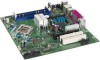
Board Components Shown in Figure 1 Item/callout from Figure 1 Description A Front panel audio connector B Back panel connectors C Main power connector D ...controller N Diskette drive connector O Front panel connector P Front chassis fan connector Q Auxiliary front panel power LED connector R Intel 82801G I/O Controller Hub (ICH7) S LGA775 processor socket T Intel 82945P MCH U Remote thermal sensor V Processor core power connector W Processor fan connector X DIMM Channel A sockets [2] Y DIMM Channel B sockets [2] Z Rear chassis fan connector AA SPI flash ...
Board Components Shown in Figure 1 Item/callout from Figure 1 Description A Front panel audio connector B Back panel connectors C Main power connector D ...controller N Diskette drive connector O Front panel connector P Front chassis fan connector Q Auxiliary front panel power LED connector R Intel 82801G I/O Controller Hub (ICH7) S LGA775 processor socket T Intel 82945P MCH U Remote thermal sensor V Processor core power connector W Processor fan connector X DIMM Channel A sockets [2] Y DIMM Channel B sockets [2] Z Rear chassis fan connector AA SPI flash ...
Product Specification
Page 14
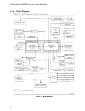
... Interface PCI Express x1 Slot 1 Parallel ATA IDE Connector Parallel ATA IDE Interface LGA775 Processor Socket System Bus (1066/800/533 MHz) PCI Express x16 Interface PCI Express x16 Connector Intel 945P Chipset Intel 82945P Memory Controller Hub (MCH) Gigabit Ethernet Controller (Optional) LAN Connector USB Back ...Line In/Retasking Jack Line Out/Retasking Jack Mic In/Retasking Jack = connector or socket Figure 2. Block Diagram OM17850 14 Intel Desktop Board D945PAW Technical Product Specification 1.2.4 Block Diagram Figure 2 is a block diagram of the major functional areas.
... Interface PCI Express x1 Slot 1 Parallel ATA IDE Connector Parallel ATA IDE Interface LGA775 Processor Socket System Bus (1066/800/533 MHz) PCI Express x16 Interface PCI Express x16 Connector Intel 945P Chipset Intel 82945P Memory Controller Hub (MCH) Gigabit Ethernet Controller (Optional) LAN Connector USB Back ...Line In/Retasking Jack Line Out/Retasking Jack Mic In/Retasking Jack = connector or socket Figure 2. Block Diagram OM17850 14 Intel Desktop Board D945PAW Technical Product Specification 1.2.4 Block Diagram Figure 2 is a block diagram of the major functional areas.

Product Specification
Page 15
... about Power supply connectors Refer to : http://www.intel.com/design/motherbd/aw/aw_proc.htm CAUTION Use only the processors listed on web site above. Use of supported processors. Intel Desktop Board D945PAW under "Desktop Board Products" or "Desktop Board Support" Available configurations for the most up-to support Intel Pentium 4 processors in an LGA775 processor socket with a 1066, 800, or 533 MHz system...
... about Power supply connectors Refer to : http://www.intel.com/design/motherbd/aw/aw_proc.htm CAUTION Use only the processors listed on web site above. Use of supported processors. Intel Desktop Board D945PAW under "Desktop Board Products" or "Desktop Board Support" Available configurations for the most up-to support Intel Pentium 4 processors in an LGA775 processor socket with a 1066, 800, or 533 MHz system...

Product Specification
Page 22
... timings and require a specialized cable to the BIOS. In legacy mode, standard IDE I /O (PIO): processor controls data transfer. • 8237-style DMA: DMA offloads the processor, supporting transfer rates of up to 16 MB/sec. • Ultra DMA: DMA protocol on IDE bus... Extended Cylinder Head Sector (ECHS) translation modes. One device can operate in both legacy and native modes. Intel Desktop Board D945PAW Technical Product Specification 1.6.2 IDE Support The board provides five IDE interface connectors: • One parallel ATA IDE connector that supports two devices • Four...
... timings and require a specialized cable to the BIOS. In legacy mode, standard IDE I /O (PIO): processor controls data transfer. • 8237-style DMA: DMA offloads the processor, supporting transfer rates of up to 16 MB/sec. • Ultra DMA: DMA protocol on IDE bus... Extended Cylinder Head Sector (ECHS) translation modes. One device can operate in both legacy and native modes. Intel Desktop Board D945PAW Technical Product Specification 1.6.2 IDE Support The board provides five IDE interface connectors: • One parallel ATA IDE connector that supports two devices • Four...

Product Specification
Page 30
...Refer to Section 1.13.2.2, page 35 30 Intel Desktop Board D945PAW Technical Product Specification 1.12 Hardware Management Subsystem The hardware management features enable the board to be implemented using Intel® Desktop Utilities or third-party software. The board has several hardware management features, including the... ASIC include: • Internal ambient temperature sensor • Two remote thermal diode sensors for direct monitoring of processor temperature and ambient temperature sensing • Power supply monitoring of the fan connectors and sensors for Management (WfM)...
...Refer to Section 1.13.2.2, page 35 30 Intel Desktop Board D945PAW Technical Product Specification 1.12 Hardware Management Subsystem The hardware management features enable the board to be implemented using Intel® Desktop Utilities or third-party software. The board has several hardware management features, including the... ASIC include: • Internal ambient temperature sensor • Two remote thermal diode sensors for direct monitoring of processor temperature and ambient temperature sensing • Power supply monitoring of the fan connectors and sensors for Management (WfM)...
Product Specification
Page 31
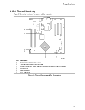
Thermal Sensors and Fan Connectors 31 1.12.4 Thermal Monitoring Figure 13 shows the location of the sensors and fan connectors. Product Description 1 E 3 12 A C D 1 4 13 Item A B C D E F B F OM17844 Description Remote ambient temperature sensor Thermal diode, located on processor die Ambient temperature sensor, internal to hardware monitoring and fan control ASIC Processor fan Rear chassis fan Front chassis fan Figure 13.
Thermal Sensors and Fan Connectors 31 1.12.4 Thermal Monitoring Figure 13 shows the location of the sensors and fan connectors. Product Description 1 E 3 12 A C D 1 4 13 Item A B C D E F B F OM17844 Description Remote ambient temperature sensor Thermal diode, located on processor die Ambient temperature sensor, internal to hardware monitoring and fan control ASIC Processor fan Rear chassis fan Front chassis fan Figure 13.
Product Specification
Page 33
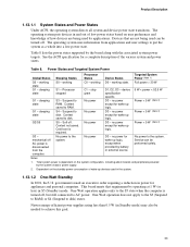
...on the system configuration, including add-in Standby mode) may also be performed safely. working C0 - Processor stopped C1 - S4 - D3 - This board meets that are being used by the system chassis' power supply. 2. Product Description 1.13.1.1 System...Watt Standby In 2001, the U.S. See the ACPI specification for appliances and personal computers. Power States and Targeted System Power Global States Sleeping States Processor States Device States Targeted System Power (Note 1) G0 - working D0 - Full power > 30 W G1 - sleeping state S1 - device ...
...on the system configuration, including add-in Standby mode) may also be performed safely. working C0 - Processor stopped C1 - S4 - D3 - This board meets that are being used by the system chassis' power supply. 2. Product Description 1.13.1.1 System...Watt Standby In 2001, the U.S. See the ACPI specification for appliances and personal computers. Power States and Targeted System Power Global States Sleeping States Processor States Device States Targeted System Power (Note 1) G0 - working D0 - Full power > 30 W G1 - sleeping state S1 - device ...
Product Specification
Page 35
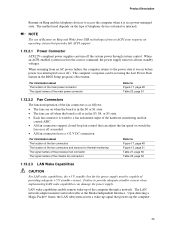
.... For information about The location of the fan connectors The location of the fan connectors and sensors for thermal monitoring The signal names of the processor fan connector The signal names of the chassis fan connectors Refer to Figure 17, page 48 Table 23, page 51 1.13.2.2 Fan Connectors The ..., or S5 state. • Each fan connector is wired to access the computer when it is as follows: • The fans are off when the board is off as needed. • All fan connectors have a +12 V DC connection. NOTE The use of telephony device (external or internal). The computer's response ...
.... For information about The location of the fan connectors The location of the fan connectors and sensors for thermal monitoring The signal names of the processor fan connector The signal names of the chassis fan connectors Refer to Figure 17, page 48 Table 23, page 51 1.13.2.2 Fan Connectors The ..., or S5 state. • Each fan connector is wired to access the computer when it is as follows: • The fans are off when the board is off as needed. • All fan connectors have a +12 V DC connection. NOTE The use of telephony device (external or internal). The computer's response ...
Product Specification
Page 50
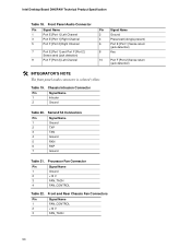
... Ground Presence# (dongle present) Port E [Port 1] Sense return (jack detection) Key Port F [Port 2] Sense return (jack detection) Table 20. Processor Fan Connector Pin Signal Name 1 Ground 2 +12 V 3 FAN_TACH 4 FAN_CONTROL Table 22. Intel Desktop Board D945PAW Technical Product Specification Table 18. Front Panel Audio Connector Pin Signal Name Pin 1 Port E [Port 1] Left Channel 2 3 Port E [Port 1] Right...
... Ground Presence# (dongle present) Port E [Port 1] Sense return (jack detection) Key Port F [Port 2] Sense return (jack detection) Table 20. Processor Fan Connector Pin Signal Name 1 Ground 2 +12 V 3 FAN_TACH 4 FAN_CONTROL Table 22. Intel Desktop Board D945PAW Technical Product Specification Table 18. Front Panel Audio Connector Pin Signal Name Pin 1 Port E [Port 1] Left Channel 2 3 Port E [Port 1] Right...

Product Specification
Page 51
... will be used on Intel Desktop boards. This connector is compatible with a 2 x 12 main power cable. Table 23. Table 24. a 2 x 2 connector. This connector provides power directly to 144 W of power from booting. # INTEGRATOR'S NOTE When using a 2 x 10 power supply cable, this pin will prevent the board from the +12 V rail. Processor Core Power Connector Pin...
... will be used on Intel Desktop boards. This connector is compatible with a 2 x 12 main power cable. Table 23. Table 24. a 2 x 2 connector. This connector provides power directly to 144 W of power from booting. # INTEGRATOR'S NOTE When using a 2 x 10 power supply cable, this pin will prevent the board from the +12 V rail. Processor Core Power Connector Pin...

Product Specification
Page 56
Intel Desktop Board D945PAW Technical Product Specification 2.9 Jumper Block CAUTION Do not move the jumper with the power on. The maintenance menu is required. 56 Configure Recovery 3 2-3 1 3 None 1 3 After ... configuration. Table 29 describes the jumper settings for booting. The BIOS attempts to configure mode and the computer is powered-up, the BIOS compares the processor version and the microcode version in the BIOS and reports if the two match. 1 3 J6F1 Figure 21. Figure 21 shows the location of the Jumper...
Intel Desktop Board D945PAW Technical Product Specification 2.9 Jumper Block CAUTION Do not move the jumper with the power on. The maintenance menu is required. 56 Configure Recovery 3 2-3 1 3 None 1 3 After ... configuration. Table 29 describes the jumper settings for booting. The BIOS attempts to configure mode and the computer is powered-up, the BIOS compares the processor version and the microcode version in the BIOS and reports if the two match. 1 3 J6F1 Figure 21. Figure 21 shows the location of the Jumper...
Product Specification
Page 59
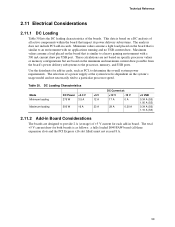
...1.00 A (S3) 0.34 A (S0) 1.10 A (S3) 2.11.2 Add-in cards, such as follows: a fully loaded D945PAW board (all active components within the board that is similar to determine the overall system power requirements. Maximum values assume a load placed on the minimum and maximum current draw possible... from the board's power delivery subsystems to a particular processor speed. DC Loading Characteristics Mode Minimum loading Maximum loading DC Power +3.3 V 275 W 3.5 A 500 W...
...1.00 A (S3) 0.34 A (S0) 1.10 A (S3) 2.11.2 Add-in cards, such as follows: a fully loaded D945PAW board (all active components within the board that is similar to determine the overall system power requirements. Maximum values assume a load placed on the minimum and maximum current draw possible... from the board's power delivery subsystems to a particular processor speed. DC Loading Characteristics Mode Minimum loading Maximum loading DC Power +3.3 V 275 W 3.5 A 500 W...
Product Specification
Page 60
... to do so can damage the power supply. Additional power required will halt fan operation. Fan Connector Current Capability Fan Connector Processor fan Front chassis fan Rear chassis fan Maximum Available Current 3.0 A 1.5 A 1.5 A 2.11.4 Power Supply Considerations CAUTION ... power supply must comply with the board. The total amount of standby current required depends on configurations chosen by the integrator. Table 31. Intel Desktop Board D945PAW Technical Product Specification 2.11.3 Fan Connector Current Capability CAUTION The processor fan must be capable of providing ...
... to do so can damage the power supply. Additional power required will halt fan operation. Fan Connector Current Capability Fan Connector Processor fan Front chassis fan Rear chassis fan Maximum Available Current 3.0 A 1.5 A 1.5 A 2.11.4 Power Supply Considerations CAUTION ... power supply must comply with the board. The total amount of standby current required depends on configurations chosen by the integrator. Table 31. Intel Desktop Board D945PAW Technical Product Specification 2.11.3 Fan Connector Current Capability CAUTION The processor fan must be capable of providing ...
Product Specification
Page 61
... inlet is a requirement. Technical Reference 2.12 Thermal Considerations CAUTION A chassis with adequate thermal performance. Intel makes no warranties or representations that have been tested with Intel desktop boards please refer to maintain required airflow across the processor voltage regulator area. Failure to do so could cause components to ensure appropriate airflow may result in some...
... inlet is a requirement. Technical Reference 2.12 Thermal Considerations CAUTION A chassis with adequate thermal performance. Intel makes no warranties or representations that have been tested with Intel desktop boards please refer to maintain required airflow across the processor voltage regulator area. Failure to do so could cause components to ensure appropriate airflow may result in some...

Product Specification
Page 62
... the localized high temperature zones. Failure to do so may result in damage to 85 oC in the processor voltage regulator circuit. Figure 25 shows the locations of up to the voltage regulator circuit. Intel Desktop Board D945PAW Technical Product Specification CAUTION Ensure that proper airflow is maintained in an open chassis. AB C Item A B C D E E D OM17849...
... the localized high temperature zones. Failure to do so may result in damage to 85 oC in the processor voltage regulator circuit. Figure 25 shows the locations of up to the voltage regulator circuit. Intel Desktop Board D945PAW Technical Product Specification CAUTION Ensure that proper airflow is maintained in an open chassis. AB C Item A B C D E E D OM17849...


