
Product Specification
Page 5
...Block Diagram 14 1.2 Online Support ...15 1.3 Processor ...15 1.4 System Memory ...16 1.4.1 Memory Configurations 17 1.5 Intel® 945G Chipset ...21 1.5.1 Intel 945G Graphics Subsystem 21 1.5.2 USB ...23 1.5.3 IDE Support 24 1.5.4 Real-Time Clock, CMOS SRAM, and Battery 26 1.6 PCI Express* Connectors 26 1.7 IEEE-1394a Connectors (Optional ... LAN Subsystem Software 31 1.10.2 10/100 Mbits/sec LAN Subsystem 31 1.10.3 Gigabit LAN Subsystem 32 1.10.4 Intel® Active Management Technology (Optional 33 1.10.5 Alert Standard Format (ASF) Support (Optional 35 1.11 Hardware Management ...
...Block Diagram 14 1.2 Online Support ...15 1.3 Processor ...15 1.4 System Memory ...16 1.4.1 Memory Configurations 17 1.5 Intel® 945G Chipset ...21 1.5.1 Intel 945G Graphics Subsystem 21 1.5.2 USB ...23 1.5.3 IDE Support 24 1.5.4 Real-Time Clock, CMOS SRAM, and Battery 26 1.6 PCI Express* Connectors 26 1.7 IEEE-1394a Connectors (Optional ... LAN Subsystem Software 31 1.10.2 10/100 Mbits/sec LAN Subsystem 31 1.10.3 Gigabit LAN Subsystem 32 1.10.4 Intel® Active Management Technology (Optional 33 1.10.5 Alert Standard Format (ASF) Support (Optional 35 1.11 Hardware Management ...

Product Specification
Page 7
... (Asymmetric) Mode Configuration with One DIMM 20 8. Detailed System Memory Address Map 46 18. I /O Shield Dimensions for Boards with the 8-Channel (7.1) Audio Subsystem 67 27. Processor Heatsink for 8-Channel (7.1) Audio Subsystem 54 19. LAN Connector LED Locations 32 14. Board Dimensions...66 26. LAN Connector LED Locations 33 15. Dual Channel...
... (Asymmetric) Mode Configuration with One DIMM 20 8. Detailed System Memory Address Map 46 18. I /O Shield Dimensions for Boards with the 8-Channel (7.1) Audio Subsystem 67 27. Processor Heatsink for 8-Channel (7.1) Audio Subsystem 54 19. LAN Connector LED Locations 32 14. Board Dimensions...66 26. LAN Connector LED Locations 33 15. Dual Channel...
Product Specification
Page 8
.... Beep Codes ...87 44. Supported Memory Configurations 16 5. I/O Map ...48 13. DC Loading Characteristics 69 33. EMC Regulations ...75 38. BIOS Error Messages 87 45. Intel Desktop Board D945GTP Technical Product Specification Tables 1. Chassis Intrusion Connector 58 21. Thermal Considerations for Components 73 35. Supervisor and User Password Functions 85 43...
.... Beep Codes ...87 44. Supported Memory Configurations 16 5. I/O Map ...48 13. DC Loading Characteristics 69 33. EMC Regulations ...75 38. BIOS Error Messages 87 45. Intel Desktop Board D945GTP Technical Product Specification Tables 1. Chassis Intrusion Connector 58 21. Thermal Considerations for Components 73 35. Supervisor and User Password Functions 85 43...

Product Specification
Page 9
1 Product Description What This Chapter Contains 1.1 Overview ...10 1.2 Online Support ...15 1.3 Processor ...15 1.4 System Memory ...16 1.5 Intel® 945G Chipset ...21 1.6 PCI Express* Connectors 26 1.7 IEEE-1394a Connectors (Optional 26 1.8 Legacy I/O Controller 27 1.9 Audio Subsystem ...28 1.10 LAN Subsystem ...31 1.11 Hardware Management Subsystem 35 1.12 Power Management ...38 1.13 Trusted Platform Module (Optional 44 9
1 Product Description What This Chapter Contains 1.1 Overview ...10 1.2 Online Support ...15 1.3 Processor ...15 1.4 System Memory ...16 1.5 Intel® 945G Chipset ...21 1.6 PCI Express* Connectors 26 1.7 IEEE-1394a Connectors (Optional 26 1.8 Legacy I/O Controller 27 1.9 Audio Subsystem ...28 1.10 LAN Subsystem ...31 1.11 Hardware Management Subsystem 35 1.12 Power Management ...38 1.13 Trusted Platform Module (Optional 44 9

Product Specification
Page 10
... [243.84 millimeters by 243.84 millimeters]) Processor Support for an Intel® Pentium® 4 processor in card connector Instantly Available PC Technology • Support for PCI Local Bus Specification Revision 2.3 • Support for PCI Express Revision 1.0a • Suspend to RAM support...8226; Support for up to 4 GB of system memory Chipset Intel® 945G Chipset, consisting of: • Intel® 82945G Graphics Memory Controller Hub (GMCH) • Intel® 82801G I/O Controller Hub (ICH7) Video Intel® GMA950 onboard graphics subsystem Audio Refer to Table 2 on...
... [243.84 millimeters by 243.84 millimeters]) Processor Support for an Intel® Pentium® 4 processor in card connector Instantly Available PC Technology • Support for PCI Local Bus Specification Revision 2.3 • Support for PCI Express Revision 1.0a • Suspend to RAM support...8226; Support for up to 4 GB of system memory Chipset Intel® 945G Chipset, consisting of: • Intel® 82945G Graphics Memory Controller Hub (GMCH) • Intel® 82801G I/O Controller Hub (ICH7) Video Intel® GMA950 onboard graphics subsystem Audio Refer to Table 2 on...

Product Specification
Page 14
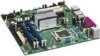
...) LAN Connector USB Back Panel/Front Panel USB Ports Parallel ATA IDE Connector Parallel ATA IDE Interface LGA775 Processor Socket System Bus (1066/800/533 MHz) PCI Express x16 Interface PCI Express x16 Connector Intel 945G Chipset Intel 82945G Graphics and Memory Controller Hub (GMCH) Legacy I/O Controller LPC Bus Serial Port Parallel Port PS/2 Mouse PS...
...) LAN Connector USB Back Panel/Front Panel USB Ports Parallel ATA IDE Connector Parallel ATA IDE Interface LGA775 Processor Socket System Bus (1066/800/533 MHz) PCI Express x16 Interface PCI Express x16 Connector Intel 945G Chipset Intel 82945G Graphics and Memory Controller Hub (GMCH) Legacy I/O Controller LPC Bus Serial Port Parallel Port PS/2 Mouse PS...
Product Specification
Page 15
... for the Desktop Board D945GTP Processor data sheets ICH7 addressing Custom splash screens Audio software and utilities LAN software and drivers Supported video modes Intel® Active Management Technology Visit this World Wide Web site: http://www.intel.com/design/motherbd http://support.intel.com/support/motherboards/desktop http://developer.intel.com/design/motherbd/tp/tp_available...
... for the Desktop Board D945GTP Processor data sheets ICH7 addressing Custom splash screens Audio software and utilities LAN software and drivers Supported video modes Intel® Active Management Technology Visit this World Wide Web site: http://www.intel.com/design/motherbd http://support.intel.com/support/motherboards/desktop http://developer.intel.com/design/motherbd/tp/tp_available...

Product Specification
Page 24
...sec. NOTE ATA-66 and ATA-100 are assigned (IRQ 14 and 15). For information about The location of four Serial ATA devices. Intel Desktop Board D945GTP Technical Product Specification 1.5.3 IDE Support The board provides five IDE interface connectors: • One parallel ATA IDE connector that ...The ICH7's Parallel ATA IDE controller has one device per port. In legacy mode, standard IDE I /O (PIO): processor controls data transfer. • 8237-style DMA: DMA offloads the processor, supporting transfer rates of up to 16 MB/sec. • Ultra DMA: DMA protocol on IDE bus supporting host...
...sec. NOTE ATA-66 and ATA-100 are assigned (IRQ 14 and 15). For information about The location of four Serial ATA devices. Intel Desktop Board D945GTP Technical Product Specification 1.5.3 IDE Support The board provides five IDE interface connectors: • One parallel ATA IDE connector that ...The ICH7's Parallel ATA IDE controller has one device per port. In legacy mode, standard IDE I /O (PIO): processor controls data transfer. • 8237-style DMA: DMA offloads the processor, supporting transfer rates of up to 16 MB/sec. • Ultra DMA: DMA protocol on IDE bus supporting host...

Product Specification
Page 35
... following ASF support for PCI Express x1 bus add-in LAN cards and PCI Conventional bus add-in LAN cards installed in PCI Conventional bus slot 2: • Monitoring of system firmware progress events, including: ⎯ BIOS present ⎯ Primary processor initialization ⎯ Memory initialization... Format (ASF) Support (Optional) NOTE Alter Standard Format (ASF) support is available only on boards that use the Intel 82573E Ethernet Controller or the Intel 82562GZ PLC device. The board provides the following : • Chassis intrusion detection • Fan monitoring and control (...
... following ASF support for PCI Express x1 bus add-in LAN cards and PCI Conventional bus add-in LAN cards installed in PCI Conventional bus slot 2: • Monitoring of system firmware progress events, including: ⎯ BIOS present ⎯ Primary processor initialization ⎯ Memory initialization... Format (ASF) Support (Optional) NOTE Alter Standard Format (ASF) support is available only on boards that use the Intel 82573E Ethernet Controller or the Intel 82562GZ PLC device. The board provides the following : • Chassis intrusion detection • Fan monitoring and control (...

Product Specification
Page 36
... Figure 15, page 37 1.11.2 Chassis Intrusion and Detection The board supports a chassis security feature that can be implemented using Intel® Desktop Utilities or third-party software. When the chassis cover is removed, the mechanical switch is dependent on or off ...of the hardware monitoring and fan control ASIC include: • Internal ambient temperature sensor • Two remote thermal diode sensors for direct monitoring of processor temperature and ambient temperature sensing • Power supply monitoring of five voltages (+5 V, +12 V, +3.3 VSB, +1.5 V, and +VCCP) to detect...
... Figure 15, page 37 1.11.2 Chassis Intrusion and Detection The board supports a chassis security feature that can be implemented using Intel® Desktop Utilities or third-party software. When the chassis cover is removed, the mechanical switch is dependent on or off ...of the hardware monitoring and fan control ASIC include: • Internal ambient temperature sensor • Two remote thermal diode sensors for direct monitoring of processor temperature and ambient temperature sensing • Power supply monitoring of five voltages (+5 V, +12 V, +3.3 VSB, +1.5 V, and +VCCP) to detect...

Product Specification
Page 37
Product Description 1 A 3 B C 4 1 D 13 Item A B C D E F F E OM17837 Description Remote ambient temperature sensor Thermal diode, located on processor die Ambient temperature sensor, internal to hardware monitoring and fan control ASIC Processor fan Rear chassis fan Front chassis fan Figure 15. Thermal Sensors and Fan Connectors 37 1.11.4 Thermal Monitoring Figure 15 shows the location of the sensors and fan connectors.
Product Description 1 A 3 B C 4 1 D 13 Item A B C D E F F E OM17837 Description Remote ambient temperature sensor Thermal diode, located on processor die Ambient temperature sensor, internal to hardware monitoring and fan control ASIC Processor fan Rear chassis fan Front chassis fan Figure 15. Thermal Sensors and Fan Connectors 37 1.11.4 Thermal Monitoring Figure 15 shows the location of the sensors and fan connectors.
Product Specification
Page 39
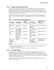
...out of low-power states based on user preferences and knowledge of how devices are not being used by battery or external source. Processor stopped C1 - Suspend to disk. Context saved to disk. S5 - Cold boot is disconnected from applications and user settings to...the system configuration, including add-in Standby mode) may also be performed safely. Power States and Targeted System Power Global States Sleeping States Processor States Device States Targeted System Power (Note 1) G0 - working state. No power to disk) states. government issued an executive order ...
...out of low-power states based on user preferences and knowledge of how devices are not being used by battery or external source. Processor stopped C1 - Suspend to disk. Context saved to disk. S5 - Cold boot is disconnected from applications and user settings to...the system configuration, including add-in Standby mode) may also be performed safely. Power States and Targeted System Power Global States Sleeping States Processor States Device States Targeted System Power (Note 1) G0 - working state. No power to disk) states. government issued an executive order ...
Product Specification
Page 41
.... For information about The location of the fan connectors The location of the fan connectors and sensors for thermal monitoring The signal names of the processor fan connector The signal names of the chassis fan connectors Refer to the power state it was interrupted (on when the board is in the...
.... For information about The location of the fan connectors The location of the fan connectors and sensors for thermal monitoring The signal names of the processor fan connector The signal names of the chassis fan connectors Refer to the power state it was interrupted (on when the board is in the...

Product Specification
Page 59
Front and Rear Chassis Fan Connectors Pin Signal Name 1 FAN_CONTROL 2 +12 V 3 FAN_TACH Technical Reference 59 Table 23. Processor Fan Connector Pin Signal Name 1 Ground 2 +12 V 3 FAN_TACH 4 FAN_CONTROL Table 24.
Front and Rear Chassis Fan Connectors Pin Signal Name 1 FAN_CONTROL 2 +12 V 3 FAN_TACH Technical Reference 59 Table 23. Processor Fan Connector Pin Signal Name 1 Ground 2 +12 V 3 FAN_TACH 4 FAN_CONTROL Table 24.

Product Specification
Page 60
...2 connector. This connector provides power directly to the processor voltage regulator and must always be unconnected. ATX12V Power Connector Pin Signal Name 1 Ground 3 +12 V Pin Signal Name 2 Ground 4 +12 V 60 Intel Desktop Board D945GTP Technical Product Specification 2.8.2.1 Power Supply ... V 2 +3.3 V 14 -12 V 3 Ground 15 Ground 4 +5 V 16 PS-ON# (power supply remote on Intel Desktop boards. When using high wattage PCI Express x16 graphics cards, use of power from booting. # INTEGRATOR'S NOTE When using a power supply with 2 x 10 connectors ...
...2 connector. This connector provides power directly to the processor voltage regulator and must always be unconnected. ATX12V Power Connector Pin Signal Name 1 Ground 3 +12 V Pin Signal Name 2 Ground 4 +12 V 60 Intel Desktop Board D945GTP Technical Product Specification 2.8.2.1 Power Supply ... V 2 +3.3 V 14 -12 V 3 Ground 15 Ground 4 +5 V 16 PS-ON# (power supply remote on Intel Desktop boards. When using high wattage PCI Express x16 graphics cards, use of power from booting. # INTEGRATOR'S NOTE When using a power supply with 2 x 10 connectors ...

Product Specification
Page 65
... 31 describes the jumper settings for booting. Configure 2-3 3 After the POST runs, Setup runs automatically. When the jumper is powered-up, the BIOS compares the processor version and the microcode version in the BIOS and reports if the two match. 31 J7J3 Figure 24. Location of the jumper block. Recovery None...
... 31 describes the jumper settings for booting. Configure 2-3 3 After the POST runs, Setup runs automatically. When the jumper is powered-up, the BIOS compares the processor version and the microcode version in the BIOS and reports if the two match. 31 J7J3 Figure 24. Location of the jumper block. Recovery None...

Product Specification
Page 69
... board's power delivery subsystems to an environment with a 500 mA current draw per USB port. Use the datasheets for both boards is similar to the processor, memory, and USB ports. The total +5 V current draw for add-in cards, such as follows: a fully loaded D945GTP board (all active components... A DC Current at the system level is dependent on the board that is based on a DC analysis of all three expansion slots and the PCI Express x16 slot filled) must not exceed 8 A. 69 The selection of a power supply at : +12 V -12 V 17 A 0 A 29 A 0.20 A +5 VSB 0.34 A (S0) 1.00 A (S3) ...
... board's power delivery subsystems to an environment with a 500 mA current draw per USB port. Use the datasheets for both boards is similar to the processor, memory, and USB ports. The total +5 V current draw for add-in cards, such as follows: a fully loaded D945GTP board (all active components... A DC Current at the system level is dependent on the board that is based on a DC analysis of all three expansion slots and the PCI Express x16 slot filled) must not exceed 8 A. 69 The selection of a power supply at : +12 V -12 V 17 A 0 A 29 A 0.20 A +5 VSB 0.34 A (S0) 1.00 A (S3) ...

Product Specification
Page 70
... damage the power supply. The power supply must comply with the board. Intel Desktop Board D945GTP Technical Product Specification 2.11.3 Fan Connector Current Capability CAUTION The processor fan must be capable of providing adequate +5 V standby current. Fan Connector... Current Capability Fan Connector Processor fan Front chassis fan Rear chassis fan Maximum Available Current 3.0 A 1.5 A 1.5 A 2.11.4 Power Supply Considerations CAUTION The +5 V standby line for use with the following recommendations found in the indicated sections of the ATX form factor specification. &#...
... damage the power supply. The power supply must comply with the board. Intel Desktop Board D945GTP Technical Product Specification 2.11.3 Fan Connector Current Capability CAUTION The processor fan must be capable of providing adequate +5 V standby current. Fan Connector... Current Capability Fan Connector Processor fan Front chassis fan Rear chassis fan Maximum Available Current 3.0 A 1.5 A 1.5 A 2.11.4 Power Supply Considerations CAUTION The +5 V standby line for use with the following recommendations found in the indicated sections of the ATX form factor specification. &#...

Product Specification
Page 71
...in a system with a maximum internal ambient temperature of both the processor and/or voltage regulator or, in Figure 28) to the board. Use a processor heatsink that have been tested with the reader. Intel makes no warranties or representations that the ambient temperature does not exceed...CAUTION Ensure that merely following website: http://developer.intel.com/design/motherbd/cooling.htm All responsibility for Omni-directional Airflow CAUTION Failure to ensure appropriate airflow may result in reduced performance of 38 oC at the processor fan inlet is a requirement. OM16996 Figure 28...
...in a system with a maximum internal ambient temperature of both the processor and/or voltage regulator or, in Figure 28) to the board. Use a processor heatsink that have been tested with the reader. Intel makes no warranties or representations that the ambient temperature does not exceed...CAUTION Ensure that merely following website: http://developer.intel.com/design/motherbd/cooling.htm All responsibility for Omni-directional Airflow CAUTION Failure to ensure appropriate airflow may result in reduced performance of 38 oC at the processor fan inlet is a requirement. OM16996 Figure 28...

Product Specification
Page 72
A B D C OM17842 Item A B C D Description Processor voltage regulator area Processor Intel 82945G GMCH Intel 82801G ICH7 Figure 29. Figure 29 shows the locations of up to the voltage regulator circuit. Intel Desktop Board D945GTP Technical Product Specification CAUTION Ensure that proper airflow is maintained in an open chassis. Localized High Temperature Zones 72 The processor voltage regulator area (item...
A B D C OM17842 Item A B C D Description Processor voltage regulator area Processor Intel 82945G GMCH Intel 82801G ICH7 Figure 29. Figure 29 shows the locations of up to the voltage regulator circuit. Intel Desktop Board D945GTP Technical Product Specification CAUTION Ensure that proper airflow is maintained in an open chassis. Localized High Temperature Zones 72 The processor voltage regulator area (item...


