Product Specification
Page 6
... BIOS Flash Memory Organization 66 3.3 Resource Configuration 66 3.3.1 PCI Autoconfiguration 66 3.3.2 PCI IDE Support 66 3.4 System Management BIOS (SMBIOS 67 3.5 Legacy USB Support...67 3.6 BIOS Updates ...68 3.6.1 Language Support 68 3.6.2 Custom Splash Screen 68 3.7 Boot Options ...69 3.7.1 CD-ROM Boot 69 3.7.2 Network Boot 69 3.7.3 Booting Without Attached Devices 69 3.7.4 Changing the Default Boot Device During POST 69 3.8 Fast Booting Systems with Intel® Rapid BIOS Boot 70 3.8.1 Peripheral Selection and Configuration 70 3.8.2 Intel Rapid BIOS Boot 70 3.9 BIOS Security...
... BIOS Flash Memory Organization 66 3.3 Resource Configuration 66 3.3.1 PCI Autoconfiguration 66 3.3.2 PCI IDE Support 66 3.4 System Management BIOS (SMBIOS 67 3.5 Legacy USB Support...67 3.6 BIOS Updates ...68 3.6.1 Language Support 68 3.6.2 Custom Splash Screen 68 3.7 Boot Options ...69 3.7.1 CD-ROM Boot 69 3.7.2 Network Boot 69 3.7.3 Booting Without Attached Devices 69 3.7.4 Changing the Default Boot Device During POST 69 3.8 Fast Booting Systems with Intel® Rapid BIOS Boot 70 3.8.1 Peripheral Selection and Configuration 70 3.8.2 Intel Rapid BIOS Boot 70 3.9 BIOS Security...

Product Specification
Page 7
... Shown in Figure 1 13 4. Supported Memory Configurations 16 5. Power States and Targeted System Power 32 8. Board Components ...12 2. LAN Connector LED Locations 26 9. Board Dimensions...53 18. Front Panel Audio Connector 46 vii Single Channel (Asymmetric) Mode Configuration with Two DIMMs 18 5. PCI Configuration Space Map 39 13. Connection Diagram for IEEE 1394a Connector 51 16. Contents 4 Error Messages and Beep Codes 4.1 BIOS Error Messages 73 4.2 Port 80h POST Codes 75 4.3 Bus Initialization Checkpoints 79 4.4 Speaker ...80 4.5 BIOS Beep Codes...80 Figures 1.
... Shown in Figure 1 13 4. Supported Memory Configurations 16 5. Power States and Targeted System Power 32 8. Board Components ...12 2. LAN Connector LED Locations 26 9. Board Dimensions...53 18. Front Panel Audio Connector 46 vii Single Channel (Asymmetric) Mode Configuration with Two DIMMs 18 5. PCI Configuration Space Map 39 13. Connection Diagram for IEEE 1394a Connector 51 16. Contents 4 Error Messages and Beep Codes 4.1 BIOS Error Messages 73 4.2 Port 80h POST Codes 75 4.3 Bus Initialization Checkpoints 79 4.4 Speaker ...80 4.5 BIOS Beep Codes...80 Figures 1.

Product Specification
Page 8
... 64 36. BIOS Setup Program Function Keys 66 38. BIOS Error Messages 73 41. Bus Initialization Checkpoints 79 45. Auxiliary Front Panel Power/Sleep LED Connector 48 25. Front Panel Connector 48 26. Boot Device Menu Options 69 39. BIOS Setup Configuration Jumper Settings 52 29. EMC Regulations ...61 35. Runtime Code Uncompressed in F000 Shadow RAM 76 44. Intel Desktop Board D910GLDW Technical Product Specification 18. Processor Fan Connector 46 20. Beep Codes ...80 viii Front Chassis Fan and Rear Chassis Fan Connectors 46 19. Main Power Connector 47 23...
... 64 36. BIOS Setup Program Function Keys 66 38. BIOS Error Messages 73 41. Bus Initialization Checkpoints 79 45. Auxiliary Front Panel Power/Sleep LED Connector 48 25. Front Panel Connector 48 26. Boot Device Menu Options 69 39. BIOS Setup Configuration Jumper Settings 52 29. EMC Regulations ...61 35. Runtime Code Uncompressed in F000 Shadow RAM 76 44. Intel Desktop Board D910GLDW Technical Product Specification 18. Processor Fan Connector 46 20. Beep Codes ...80 viii Front Chassis Fan and Rear Chassis Fan Connectors 46 19. Main Power Connector 47 23...

Product Specification
Page 9
... What This Chapter Contains 1.1 PCI Bus Terminology Change 9 1.2 Overview ...10 1.3 Online Support ...15 1.4 Processor ...15 1.5 System Memory ...15 1.6 Intel® 910GL Chipset 19 1.7 PCI Express Connector 22 1.8 I/O Controller...23 1.9 Audio Subsystem ...24 1.10 LAN Subsystem (Optional 26 1.11 Hardware Management Subsystem 28 1.12 Power Management ...30 1.1 PCI Bus Terminology Change Previous generations of Intel Desktop Boards adds a new technology for add-in card connector referred to as PCI. This generation of Intel® Desktop Boards used an add-in cards: PCI Express*.
... What This Chapter Contains 1.1 PCI Bus Terminology Change 9 1.2 Overview ...10 1.3 Online Support ...15 1.4 Processor ...15 1.5 System Memory ...15 1.6 Intel® 910GL Chipset 19 1.7 PCI Express Connector 22 1.8 I/O Controller...23 1.9 Audio Subsystem ...24 1.10 LAN Subsystem (Optional 26 1.11 Hardware Management Subsystem 28 1.12 Power Management ...30 1.1 PCI Bus Terminology Change Previous generations of Intel Desktop Boards adds a new technology for add-in card connector referred to as PCI. This generation of Intel® Desktop Boards used an add-in cards: PCI Express*.

Product Specification
Page 10
... ATA IDE interface with UDMA 33, ATA-66/100 support • One diskette drive interface • PS/2* keyboard and mouse ports • 4 Mbit FWH • Intel® Rapid BIOS Boot • Support for Advanced Configuration and Power Interface (ACPI), Plug and Play, and SMBIOS • Support for PCI Local Bus Specification Revision 2.2 • Support for PCI Express Revision 1.0a • Suspend to RAM support • Wake on PCI, RS-232, front panel, PS/2 devices, and USB ports continued...
... ATA IDE interface with UDMA 33, ATA-66/100 support • One diskette drive interface • PS/2* keyboard and mouse ports • 4 Mbit FWH • Intel® Rapid BIOS Boot • Support for Advanced Configuration and Power Interface (ACPI), Plug and Play, and SMBIOS • Support for PCI Local Bus Specification Revision 2.2 • Support for PCI Express Revision 1.0a • Suspend to RAM support • Wake on PCI, RS-232, front panel, PS/2 devices, and USB ports continued...
Product Specification
Page 14
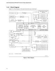
Intel Desktop Board D910GLDW Technical Product Specification 1.2.4 Block Diagram Figure 2 is a block diagram of the major functional areas of the board. PCI Express x1 Slot 1 PCI Express x1 Interface Parallel ATA IDE Connector LGA775 Processor Socket Parallel ATA IDE Interface System Bus (533 MHz) USB Back Panel/Front Panel USB Ports LPC Bus I/O Controller LPC Bus Serial Ports Parallel Port PS/2 Mouse PS/2 Keyboard Diskette Drive Connector DMI Interconnect High Definition Audio Link LAN Connect Interface Intel 82910GL Graphics and Memory Controller Hub (GMCH) VGA Port Channel A...
Intel Desktop Board D910GLDW Technical Product Specification 1.2.4 Block Diagram Figure 2 is a block diagram of the major functional areas of the board. PCI Express x1 Slot 1 PCI Express x1 Interface Parallel ATA IDE Connector LGA775 Processor Socket Parallel ATA IDE Interface System Bus (533 MHz) USB Back Panel/Front Panel USB Ports LPC Bus I/O Controller LPC Bus Serial Ports Parallel Port PS/2 Mouse PS/2 Keyboard Diskette Drive Connector DMI Interconnect High Definition Audio Link LAN Connect Interface Intel 82910GL Graphics and Memory Controller Hub (GMCH) VGA Port Channel A...
Product Specification
Page 16
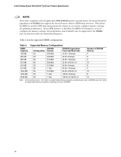
Table 4 lists the supported DIMM configurations. Intel Desktop Board D910GLDW Technical Product Specification NOTE To be fully compliant with all applicable DDR SDRAM memory specifications, the board should be impacted or the DIMMs may not function under the determined frequency. Supported Memory Configurations DIMM Capacity SDRAM Configuration Density SDRAM Organization Front-side/Back-side Number of SDRAM Devices 128 MB SS 256 Mbit 16 M x 16/empty 4 256 MB...
Table 4 lists the supported DIMM configurations. Intel Desktop Board D910GLDW Technical Product Specification NOTE To be fully compliant with all applicable DDR SDRAM memory specifications, the board should be impacted or the DIMMs may not function under the determined frequency. Supported Memory Configurations DIMM Capacity SDRAM Configuration Density SDRAM Organization Front-side/Back-side Number of SDRAM Devices 128 MB SS 256 Mbit 16 M x 16/empty 4 256 MB...

Product Specification
Page 20
... IDE connector that supports two devices • Four serial ATA IDE connectors that meets the requirements for all ports. NOTE The use of this would be allocated to the audio connectors • Four ports are implemented with legacy applications. Intel Desktop Board D910GLDW Technical Product Specification 1.6.1.1 Dynamic Video Memory Technology (DVMT) DVMT enables enhanced graphics and memory performance through Direct AGP, and highly efficient memory utilization. Up to 128 MB can be when using VGA graphics under DOS. Use shielded cable that support...
... IDE connector that supports two devices • Four serial ATA IDE connectors that meets the requirements for all ports. NOTE The use of this would be allocated to the audio connectors • Four ports are implemented with legacy applications. Intel Desktop Board D910GLDW Technical Product Specification 1.6.1.1 Dynamic Video Memory Technology (DVMT) DVMT enables enhanced graphics and memory performance through Direct AGP, and highly efficient memory utilization. Up to 128 MB can be when using VGA graphics under DOS. Use shielded cable that support...

Product Specification
Page 21
...'s Serial ATA controller offers four independent Serial ATA ports with a theoretical maximum transfer rate of 150 MB/s per channel. hard disk drive) For information about The location of the Parallel ATA IDE connector Refer to the BIOS. For compatibility, the underlying Serial ATA functionality is the preferred mode for configurations using the transfer modes. Native mode is transparent to device connections, unlike Parallel ATA IDE which supports a master/slave configuration and two devices per port. The BIOS supports...
...'s Serial ATA controller offers four independent Serial ATA ports with a theoretical maximum transfer rate of 150 MB/s per channel. hard disk drive) For information about The location of the Parallel ATA IDE connector Refer to the BIOS. For compatibility, the underlying Serial ATA functionality is the preferred mode for configurations using the transfer modes. Native mode is transparent to device connections, unlike Parallel ATA IDE which supports a master/slave configuration and two devices per port. The BIOS supports...
Product Specification
Page 22
... underlying PCI Express architecture is plugged in the PCI Power Management Specification Rev. 1.1 22 For more information, see: http://www.serialata.org/ For information about The location of three years. The x1 interface supports simultaneous transfer speeds up to Figure 12, page 44 1.6.4 Real-Time Clock, CMOS SRAM, and Battery A coin-cell battery (CR2032) powers the real-time clock and CMOS memory. Intel Desktop Board D910GLDW Technical Product Specification NOTE Many Serial ATA drives use...
... underlying PCI Express architecture is plugged in the PCI Power Management Specification Rev. 1.1 22 For more information, see: http://www.serialata.org/ For information about The location of three years. The x1 interface supports simultaneous transfer speeds up to Figure 12, page 44 1.6.4 Real-Time Clock, CMOS SRAM, and Battery A coin-cell battery (CR2032) powers the real-time clock and CMOS memory. Intel Desktop Board D910GLDW Technical Product Specification NOTE Many Serial ATA drives use...
Product Specification
Page 30
... processor fan speed control remain enabled (default BIOS setting) when using Intel® Desktop Utilities, LANDesk* software, or thirdparty software. Disabling the chassis fan speed control results in the closed position. 1.12 Power Management Power management is attached to any controlled chassis fan header. Intel Desktop Board D910GLDW Technical Product Specification 1.11.3 Fan Monitoring Fan monitoring can be disabled independently through Advanced Configuration and Power Interface (ACPI) • Hardware support: ⎯ Power connector ⎯ Fan connectors ⎯ LAN wake...
... processor fan speed control remain enabled (default BIOS setting) when using Intel® Desktop Utilities, LANDesk* software, or thirdparty software. Disabling the chassis fan speed control results in the closed position. 1.12 Power Management Power management is attached to any controlled chassis fan header. Intel Desktop Board D910GLDW Technical Product Specification 1.11.3 Fan Monitoring Fan monitoring can be disabled independently through Advanced Configuration and Power Interface (ACPI) • Hardware support: ⎯ Power connector ⎯ Fan connectors ⎯ LAN wake...

Product Specification
Page 42
... computer, the power cable, and the external devices themselves. Intel Desktop Board D910GLDW Technical Product Specification 2.8 Connectors CAUTION Only the following connectors have overcurrent protection: back panel USB, front panel USB, and PS/2. C F I /O connectors (see page 44) 2.8.1 Back Panel Connectors Figure 11 shows the location of the back panel connectors. Back Panel Connectors OM17314 Table 15 lists the back panel connectors identified in the load presented by the external devices could cause damage to the computer's chassis. This...
... computer, the power cable, and the external devices themselves. Intel Desktop Board D910GLDW Technical Product Specification 2.8 Connectors CAUTION Only the following connectors have overcurrent protection: back panel USB, front panel USB, and PS/2. C F I /O connectors (see page 44) 2.8.1 Back Panel Connectors Figure 11 shows the location of the back panel connectors. Back Panel Connectors OM17314 Table 15 lists the back panel connectors identified in the load presented by the external devices could cause damage to the computer's chassis. This...

Product Specification
Page 65
... ...65 3.2 BIOS Flash Memory Organization 66 3.3 Resource Configuration 66 3.4 System Management BIOS (SMBIOS 67 3.5 Legacy USB Support...67 3.6 BIOS Updates ...68 3.7 Boot Options ...69 3.8 Fast Booting Systems with Intel® Rapid BIOS Boot 70 3.9 BIOS Security Features 71 3.1 Introduction The board uses an Intel/AMI BIOS that is shown below. Maintenance Main Advanced Security Power Boot Exit NOTE The maintenance menu is displayed only when the Desktop Board is accessed by pressing the key after the Power-On Self-Test (POST) memory test...
... ...65 3.2 BIOS Flash Memory Organization 66 3.3 Resource Configuration 66 3.4 System Management BIOS (SMBIOS 67 3.5 Legacy USB Support...67 3.6 BIOS Updates ...68 3.7 Boot Options ...69 3.8 Fast Booting Systems with Intel® Rapid BIOS Boot 70 3.9 BIOS Security Features 71 3.1 Introduction The board uses an Intel/AMI BIOS that is shown below. Maintenance Main Advanced Security Power Boot Exit NOTE The maintenance menu is displayed only when the Desktop Board is accessed by pressing the key after the Power-On Self-Test (POST) memory test...

Product Specification
Page 66
... up the PCI IDE connector with independent I /O space, and other system resources. Intel Desktop Board D910GLDW Technical Product Specification Table 36 lists the BIOS Setup program menu features. BIOS Setup Program Menu Bar Maintenance Main Advanced Security Clears passwords and displays processor information Displays processor and memory configuration Configures advanced features available through the chipset Sets passwords and security features Power Boot Configures power management features and power supply controls Selects boot options Exit Saves or discards changes to ATA...
... up the PCI IDE connector with independent I /O space, and other system resources. Intel Desktop Board D910GLDW Technical Product Specification Table 36 lists the BIOS Setup program menu features. BIOS Setup Program Menu Bar Maintenance Main Advanced Security Clears passwords and displays processor information Displays processor and memory configuration Configures advanced features available through the chipset Sets passwords and security features Power Boot Configures power management features and power supply controls Selects boot options Exit Saves or discards changes to ATA...

Product Specification
Page 67
... specifying manual configuration in a managed network. The BIOS stores and reports the following items are not yet available. By default, Legacy USB support is set to the computer, legacy support is disabled. 2. When you to use a USB keyboard to an ATAPI CD-ROM drive. 3.4 System Management BIOS (SMBIOS) SMBIOS is used even when the operating system's USB drivers are required: • An ATA-66/100 peripheral device • An ATA-66/100 compatible cable...
... specifying manual configuration in a managed network. The BIOS stores and reports the following items are not yet available. By default, Legacy USB support is set to the computer, legacy support is disabled. 2. When you to use a USB keyboard to an ATAPI CD-ROM drive. 3.4 System Management BIOS (SMBIOS) SMBIOS is used even when the operating system's USB drivers are required: • An ATA-66/100 peripheral device • An ATA-66/100 compatible cable...

Product Specification
Page 70
...; Using an optimized BIOS, such as the Intel Rapid BIOS 3.8.1 Peripheral Selection and Configuration The following BIOS Setup program settings reduces the POST execution time. This feature bypasses memory count and the search for a diskette drive. Monitors and hard disk drives with minimum initialization times can also contribute to boot more quickly. 3.8.2 Intel Rapid BIOS Boot Use of the BIOS Setup program). 70 In the Boot Menu: • Set the hard disk drive as logo displays, screen repaints, or mode changes in POST...
...; Using an optimized BIOS, such as the Intel Rapid BIOS 3.8.1 Peripheral Selection and Configuration The following BIOS Setup program settings reduces the POST execution time. This feature bypasses memory count and the search for a diskette drive. Monitors and hard disk drives with minimum initialization times can also contribute to boot more quickly. 3.8.2 Intel Rapid BIOS Boot Use of the BIOS Setup program). 70 In the Boot Menu: • Set the hard disk drive as logo displays, screen repaints, or mode changes in POST...

Product Specification
Page 74
Keyboard Error Error in onboard memory at an unknown address. Make sure keyboard is cleared. The system Jumper should be updated. Pressed CMOS is ignored and NVRAM is connected properly. User must enter Setup. 74 KB/Interface Error Keyboard interface test failed. If no memory was removed then memory may be bad. Memory Size Changed Memory size has changed since the last boot. Off Board Parity Error A parity error occurred on an off-board card. Intel Desktop Board D910GLDW Technical Product Specification Table 40. If no memory was...
Keyboard Error Error in onboard memory at an unknown address. Make sure keyboard is cleared. The system Jumper should be updated. Pressed CMOS is ignored and NVRAM is connected properly. User must enter Setup. 74 KB/Interface Error Keyboard interface test failed. If no memory was removed then memory may be bad. Memory Size Changed Memory size has changed since the last boot. Off Board Parity Error A parity error occurred on an off-board card. Intel Desktop Board D910GLDW Technical Product Specification Table 40. If no memory was...

Product Specification
Page 75
... error occurred. Error Messages and Beep Codes 4.2 Port 80h POST Codes During the POST, the BIOS generates diagnostic progress codes (POST-codes) to boot sector code. If the POST fails, execution stops and the last POST code generated is Disabled. Find Main BIOS module in card, often called a POST card. Booting from floppy and ATAPI device failed. Table 41. Initialize floppy drive. If reading of POST Operation Onboard Floppy Controller (if any) is in F000 Shadow RAM. Give two beeps. Displaying the POST-codes requires a PCI bus add-in ROM...
... error occurred. Error Messages and Beep Codes 4.2 Port 80h POST Codes During the POST, the BIOS generates diagnostic progress codes (POST-codes) to boot sector code. If the POST fails, execution stops and the last POST code generated is Disabled. Find Main BIOS module in card, often called a POST card. Booting from floppy and ATAPI device failed. Table 41. Initialize floppy drive. If reading of POST Operation Onboard Floppy Controller (if any) is in F000 Shadow RAM. Give two beeps. Displaying the POST-codes requires a PCI bus add-in ROM...

Product Specification
Page 76
... Alternate Display memory R/W test passed. To display the Hit message. continued 76 Runtime Code Uncompressed in every boot" is set . To check soft reset/power-on. 05 BIOS stack set or key is toggling. To issue the BAT command to be done next. 0C KB controller I/B free. Make BIOS code segment writeable. 24 To do any setup before optional video ROM check. 2C To look for any . 06 POST code to...
... Alternate Display memory R/W test passed. To display the Hit message. continued 76 Runtime Code Uncompressed in every boot" is set . To check soft reset/power-on. 05 BIOS stack set or key is toggling. To issue the BAT command to be done next. 0C KB controller I/B free. Make BIOS code segment writeable. 24 To do any setup before optional video ROM check. 2C To look for any . 06 POST code to...

Product Specification
Page 80
... short tones) during POST if the video configuration fails (a faulty video card or no card installed) or if an external ROM module does not properly checksum to Figure 1, page 12 4.5 BIOS Beep Codes Whenever a recoverable error occurs during POST. The BIOS also issues a beep code (one long tone followed by a series of the onboard speaker Refer to zero. Table 47. Beep Codes Beep 1 3 6 7 8 Description CPU error Memory error System failure System failure Video error 80 The speaker provides audible error code (beep code) information during POST, the BIOS displays an error...
... short tones) during POST if the video configuration fails (a faulty video card or no card installed) or if an external ROM module does not properly checksum to Figure 1, page 12 4.5 BIOS Beep Codes Whenever a recoverable error occurs during POST. The BIOS also issues a beep code (one long tone followed by a series of the onboard speaker Refer to zero. Table 47. Beep Codes Beep 1 3 6 7 8 Description CPU error Memory error System failure System failure Video error 80 The speaker provides audible error code (beep code) information during POST, the BIOS displays an error...


