
Product Specification
Page 5
...10 1.1.2 Board Layout 12 1.1.3 Block Diagram 14 1.2 Legacy Considerations 15 1.3 Online Support 15 1.4 Processor 15 1.5 System Memory 16 1.5.1 Memory Configurations 17 1.6 Intel® Q35 Express Chipset 19 1.6.1 Intel Q35 Graphics Subsystem 19 1.6.2 USB 21 1.6.3 Serial ATA Interfaces 21 1.7 Parallel IDE Controller 22 ... Software 27 1.11.3 RJ-45 LAN Connector with Integrated LEDs 27 1.12 Intel® Active Management Technology (Intel® AMT 28 1.12.1 Intel AMT Features 28 1.12.2 Intel AMT Software and Drivers 29 1.13 Hardware Management Subsystem 30 1.13.1 Hardware ...
...10 1.1.2 Board Layout 12 1.1.3 Block Diagram 14 1.2 Legacy Considerations 15 1.3 Online Support 15 1.4 Processor 15 1.5 System Memory 16 1.5.1 Memory Configurations 17 1.6 Intel® Q35 Express Chipset 19 1.6.1 Intel Q35 Graphics Subsystem 19 1.6.2 USB 21 1.6.3 Serial ATA Interfaces 21 1.7 Parallel IDE Controller 22 ... Software 27 1.11.3 RJ-45 LAN Connector with Integrated LEDs 27 1.12 Intel® Active Management Technology (Intel® AMT 28 1.12.1 Intel AMT Features 28 1.12.2 Intel AMT Software and Drivers 29 1.13 Hardware Management Subsystem 30 1.13.1 Hardware ...
Product Specification
Page 7
.... Feature Summary 10 2. Board Components Shown in Figure 11 46 13. Wake-up Devices and Events 34 10. LAN Connector LED States 27 7. Processor Core Power Connector 49 22. Main Power Connector 49 vii Supported Memory Configurations 17 4. Chassis Intrusion Header 48 18. Contents 5.1.5 Product Certification Markings ...8. LAN Connector LED Locations 27 6. Back Panel Connectors 44 11. DVI Port Status Conditions 20 5. Detailed System Memory Address Map 42 10. Processor (4-Pin) Fan Header 48 20. Effects of the Intel AMT Status Indicator LED 37 8. Block Diagram 14 3.
.... Feature Summary 10 2. Board Components Shown in Figure 11 46 13. Wake-up Devices and Events 34 10. LAN Connector LED States 27 7. Processor Core Power Connector 49 22. Main Power Connector 49 vii Supported Memory Configurations 17 4. Chassis Intrusion Header 48 18. Contents 5.1.5 Product Certification Markings ...8. LAN Connector LED Locations 27 6. Back Panel Connectors 44 11. DVI Port Status Conditions 20 5. Detailed System Memory Address Map 42 10. Processor (4-Pin) Fan Header 48 20. Effects of the Intel AMT Status Indicator LED 37 8. Block Diagram 14 3.

Product Specification
Page 9
1 Product Description What This Chapter Contains 1.1 Overview 10 1.2 Legacy Considerations 15 1.3 Online Support 15 1.4 Processor 15 1.5 System Memory 16 1.6 Intel® Q35 Express Chipset 19 1.7 Parallel IDE Controller 22 1.8 Real-Time Clock Subsystem 23 1.9 Legacy I/O Controller 23 1.10 Audio Subsystem 24 1.11 LAN Subsystem 26 1.12 Intel® Active Management Technology (Intel® AMT 28 1.13 Hardware Management Subsystem 30 1.14 Power Management 32 1.15 Trusted Platform Module (TPM 39 9
1 Product Description What This Chapter Contains 1.1 Overview 10 1.2 Legacy Considerations 15 1.3 Online Support 15 1.4 Processor 15 1.5 System Memory 16 1.6 Intel® Q35 Express Chipset 19 1.7 Parallel IDE Controller 22 1.8 Real-Time Clock Subsystem 23 1.9 Legacy I/O Controller 23 1.10 Audio Subsystem 24 1.11 LAN Subsystem 26 1.12 Intel® Active Management Technology (Intel® AMT 28 1.13 Hardware Management Subsystem 30 1.14 Power Management 32 1.15 Trusted Platform Module (TPM 39 9
Product Specification
Page 10
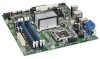
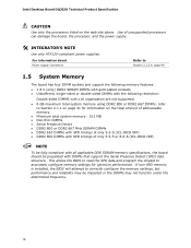
... inches by 9.60 inches [243.84 millimeters by 243.84 millimeters]) Processor Memory Chipset Support for the following: • Intel® Core™2 Quad processor in an LGA775 socket with a 1066 MHz system bus • Intel® Core™2 Duo processor in an LGA775 socket with a 1333 MHz, 1066 MHz, or 800... MHz system bus • Intel® Pentium® Dual-Core processor in an LGA775 socket with an 800 MHz system bus • Intel® Celeron® processor 400 sequence in the SPI Flash device) • Support for up to 8 GB of...
... inches by 9.60 inches [243.84 millimeters by 243.84 millimeters]) Processor Memory Chipset Support for the following: • Intel® Core™2 Quad processor in an LGA775 socket with a 1066 MHz system bus • Intel® Core™2 Duo processor in an LGA775 socket with a 1333 MHz, 1066 MHz, or 800... MHz system bus • Intel® Pentium® Dual-Core processor in an LGA775 socket with an 800 MHz system bus • Intel® Celeron® processor 400 sequence in the SPI Flash device) • Support for up to 8 GB of...

Product Specification
Page 15
...list of the DQ35JO board. Supported processors Refer to: http://www.intel.com/go /findcpu http://www.intel.com/products/desktop/chipsets/index.htm http://downloadcenter.intel.com http://support.intel.com/support/motherboards/desktop/sb/CS025414.htm 1.4 Processor The board is designed to support... Considerations This board differs from other Intel Desktop Board products, with specific changes including (but not limited to) the following processors: • Intel Core 2 Quad processor in an LGA775 socket with a 1066 MHz system bus • Intel Core 2 Duo processor in an LGA775 socket with a ...
...list of the DQ35JO board. Supported processors Refer to: http://www.intel.com/go /findcpu http://www.intel.com/products/desktop/chipsets/index.htm http://downloadcenter.intel.com http://support.intel.com/support/motherboards/desktop/sb/CS025414.htm 1.4 Processor The board is designed to support... Considerations This board differs from other Intel Desktop Board products, with specific changes including (but not limited to) the following processors: • Intel Core 2 Quad processor in an LGA775 socket with a 1066 MHz system bus • Intel Core 2 Duo processor in an LGA775 socket with a ...
Product Specification
Page 16
...• Unbuffered, single-sided or double-sided DIMMs with the following restriction: Double-sided DIMMS with SPD timings of unsupported processors can damage the board, the processor, and the power supply. # INTEGRATOR'S NOTE Use only ATX12V-compliant power supplies. For information about Power supply connectors Refer... settings, but performance and reliability may be populated with DIMMs that support the Serial Presence Detect (SPD) data structure. Intel Desktop Board DQ35JO Technical Product Specification CAUTION Use only the processors listed on page 41 for optimum performance.
...• Unbuffered, single-sided or double-sided DIMMs with the following restriction: Double-sided DIMMS with SPD timings of unsupported processors can damage the board, the processor, and the power supply. # INTEGRATOR'S NOTE Use only ATX12V-compliant power supplies. For information about Power supply connectors Refer... settings, but performance and reliability may be populated with DIMMs that support the Serial Presence Detect (SPD) data structure. Intel Desktop Board DQ35JO Technical Product Specification CAUTION Use only the processors listed on page 41 for optimum performance.

Product Specification
Page 22
Intel Desktop Board DQ35JO Technical Product Specification NOTE Many Serial ATA drives use new low-voltage power connectors and require adapters or power supplies equipped with ... Refer to Figure 11, page 45 1.6.3.2 Serial ATA RAID The DQ35JO Desktop Board supports the following modes: • Programmed I/O (PIO): processor controls data transfer. • 8237-style DMA: DMA offloads the processor, supporting transfer rates of up to 16 MB/sec. • Ultra DMA: DMA protocol on IDE bus supporting host and...
Intel Desktop Board DQ35JO Technical Product Specification NOTE Many Serial ATA drives use new low-voltage power connectors and require adapters or power supplies equipped with ... Refer to Figure 11, page 45 1.6.3.2 Serial ATA RAID The DQ35JO Desktop Board supports the following modes: • Programmed I/O (PIO): processor controls data transfer. • 8237-style DMA: DMA offloads the processor, supporting transfer rates of up to 16 MB/sec. • Ultra DMA: DMA protocol on IDE bus supporting host and...

Product Specification
Page 30
...Section 1.14.2.2, page 36 1.13.3 Chassis Intrusion and Detection The board supports a chassis security feature that detects if the chassis cover is in the processor, 82Q35 GMCH, and 82801IDO ICH9DO • Power supply monitoring of five voltages (+5 V, +12 V, +3.3 VSB, +1.25 V, and +VCCP) to...Refer to Figure 11, page 45 30 For information about The location of the hardware monitoring and fan control include: • Intel Quiet System Technology, delivering acoustically-optimized thermal management • Fan speed control controllers and sensors integrated into the ICH9DO • ...
...Section 1.14.2.2, page 36 1.13.3 Chassis Intrusion and Detection The board supports a chassis security feature that detects if the chassis cover is in the processor, 82Q35 GMCH, and 82801IDO ICH9DO • Power supply monitoring of five voltages (+5 V, +12 V, +3.3 VSB, +1.25 V, and +VCCP) to...Refer to Figure 11, page 45 30 For information about The location of the hardware monitoring and fan control include: • Intel Quiet System Technology, delivering acoustically-optimized thermal management • Fan speed control controllers and sensors integrated into the ICH9DO • ...

Product Specification
Page 31
Thermal Sensors and Fan Headers NOTE The minimum thermal reporting threshold for the GMCH is 66 °C. Item A B C D E F G Description Rear chassis fan Thermal diode, located on the GMCH die Thermal diode, located on processor die Remote thermal sensor Processor fan Thermal diode, located on the ICH9DO die Front chassis fan Figure 6. The GMCH thermal sensor will display 66 °C until the temperature rises above this point. 31 Product Description 1.13.4 Thermal Monitoring Figure 6 shows the locations of the thermal sensors and fan headers.
Thermal Sensors and Fan Headers NOTE The minimum thermal reporting threshold for the GMCH is 66 °C. Item A B C D E F G Description Rear chassis fan Thermal diode, located on the GMCH die Thermal diode, located on processor die Remote thermal sensor Processor fan Thermal diode, located on the ICH9DO die Front chassis fan Figure 6. The GMCH thermal sensor will display 66 °C until the temperature rises above this point. 31 Product Description 1.13.4 Thermal Monitoring Figure 6 shows the locations of the thermal sensors and fan headers.

Product Specification
Page 33
...all system and device power state transitions. The operating system uses information from the computer. Power States and Targeted System Power Global States Processor Sleeping States States Device States Targeted System Power (Note 1) G0 - sleeping state G1 - sleeping state G2/S5 G3 - Suspend ...power supply. 2. working state S0 - stop grant G1 - Context saved to RAM. working C0 - Full power > 30 W G1 - Processor stopped C1 - Context saved to disk. no power except for a complete description of how devices are not being used in and out of low...
...all system and device power state transitions. The operating system uses information from the computer. Power States and Targeted System Power Global States Processor Sleeping States States Device States Targeted System Power (Note 1) G0 - sleeping state G1 - sleeping state G2/S5 G3 - Suspend ...power supply. 2. working state S0 - stop grant G1 - Context saved to RAM. working C0 - Full power > 30 W G1 - Processor stopped C1 - Context saved to disk. no power except for a complete description of how devices are not being used in and out of low...

Product Specification
Page 36
... detecting a Magic Packet* frame, the LAN subsystem asserts a wake-up signal that can be enabled in the S3, S4, or S5 state. • The processor fan header is off as needed. • All fan headers have a +12 V DC connection. For information about The locations of the fan headers and thermal...for PCI 2.3 compliant LAN designs ⎯ By Ping ⎯ Magic Packet • The onboard LAN subsystem 1.14.2.4 Intel® Management Engine Wake-on or off or in the BIOS and allows Intel AMT to Figure 6, page 31 Table 19, page 48 Table 18, page 48 1.14.2.3 LAN Wake Capabilities CAUTION For...
... detecting a Magic Packet* frame, the LAN subsystem asserts a wake-up signal that can be enabled in the S3, S4, or S5 state. • The processor fan header is off as needed. • All fan headers have a +12 V DC connection. For information about The locations of the fan headers and thermal...for PCI 2.3 compliant LAN designs ⎯ By Ping ⎯ Magic Packet • The onboard LAN subsystem 1.14.2.4 Intel® Management Engine Wake-on or off or in the BIOS and allows Intel AMT to Figure 6, page 31 Table 19, page 48 Table 18, page 48 1.14.2.3 LAN Wake Capabilities CAUTION For...

Product Specification
Page 48
...to pin A40. ⎯ The SMBus data line is bus master capable. • SMBus signals are routed to pin A41. 48 Intel Desktop Board DQ35JO Technical Product Specification Table 17. PCI Conventional bus add-in card connectors: • PCI Express x16: one PCI ...has the following considerations for the PCI Conventional bus connector: • The PCI Conventional bus connector is connected to the PCI Conventional bus connector. Processor (4-Pin) Fan Header Pin Signal Name 1 Ground 2 +12 V 3 FAN_TACH 4 FAN_CONTROL 2.2.2.2 Add-in boards with SMBus support can access sensor...
...to pin A40. ⎯ The SMBus data line is bus master capable. • SMBus signals are routed to pin A41. 48 Intel Desktop Board DQ35JO Technical Product Specification Table 17. PCI Conventional bus add-in card connectors: • PCI Express x16: one PCI ...has the following considerations for the PCI Conventional bus connector: • The PCI Conventional bus connector is connected to the PCI Conventional bus connector. Processor (4-Pin) Fan Header Pin Signal Name 1 Ground 2 +12 V 3 FAN_TACH 4 FAN_CONTROL 2.2.2.2 Add-in boards with SMBus support can access sensor...
Product Specification
Page 49
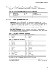
...the main power connector, leaving pins 11, 12, 23, and 24 unconnected. • Processor core power - This connector provides power directly to the processor voltage regulator and must always be unconnected. a 2 x 12 connector. Processor Core Power Connector Pin Signal Name 1 Ground 3 +12 V Pin Signal Name 2 ... 2 and 4 of the front panel header. For information about Power supply considerations Refer to do so will be used on Intel Desktop boards. Auxiliary Front Panel Power/Sleep LED Header Pin Signal Name 1 HDR_BLNK_GRN 2 Not connected 3 HDR_BLNK_YEL In/Out Out ...
...the main power connector, leaving pins 11, 12, 23, and 24 unconnected. • Processor core power - This connector provides power directly to the processor voltage regulator and must always be unconnected. a 2 x 12 connector. Processor Core Power Connector Pin Signal Name 1 Ground 3 +12 V Pin Signal Name 2 ... 2 and 4 of the front panel header. For information about Power supply considerations Refer to do so will be used on Intel Desktop boards. Auxiliary Front Panel Power/Sleep LED Header Pin Signal Name 1 HDR_BLNK_GRN 2 Not connected 3 HDR_BLNK_YEL In/Out Out ...

Product Specification
Page 53
... jumper with the power on BIOS recovery. 53 Location of the Jumper Block Table 26. The maintenance menu is powered-up, the BIOS compares the processor version and the microcode version in the BIOS and reports if the two match. Otherwise, the board could be damaged. When the jumper is set...
... jumper with the power on BIOS recovery. 53 Location of the Jumper Block Table 26. The maintenance menu is powered-up, the BIOS compares the processor version and the microcode version in the BIOS and reports if the two match. Otherwise, the board could be damaged. When the jumper is set...

Product Specification
Page 55
...55 Table 27 lists the recommended power supply current values. Connecting the processor fan to http://support.intel.com/support/motherboards/desk top/sb/CS-026472.htm 2.5.2 Fan Header Current Capability CAUTION The processor fan must comply with the indicated parameters of the ATX form factor ...8226; All timing parameters • All voltage tolerances For example, for a system consisting of a supported 65 W processor (see Section 1.4 on page 15 for a list of supported processors), 1 GB DDR2 RAM, one hard disk drive, one optical drive, and all board peripherals enabled, the minimum ...
...55 Table 27 lists the recommended power supply current values. Connecting the processor fan to http://support.intel.com/support/motherboards/desk top/sb/CS-026472.htm 2.5.2 Fan Header Current Capability CAUTION The processor fan must comply with the indicated parameters of the ATX form factor ...8226; All timing parameters • All voltage tolerances For example, for a system consisting of a supported 65 W processor (see Section 1.4 on page 15 for a list of supported processors), 1 GB DDR2 RAM, one hard disk drive, one optical drive, and all board peripherals enabled, the minimum ...

Product Specification
Page 56
... appropriate airflow may result in reduced performance of 38 oC at the processor fan inlet is designed to the board. Intel makes no warranties or representations that have been tested with Intel desktop boards please refer to the following the instructions presented in this ...not exceed 14 A. 2.6 Thermal Considerations CAUTION A chassis with the reader. Intel Desktop Board DQ35JO Technical Product Specification Table 28 lists the current capability of +5 V current for each add-in board. Use a processor heat sink that the ambient temperature does not exceed the board's maximum ...
... appropriate airflow may result in reduced performance of 38 oC at the processor fan inlet is designed to the board. Intel makes no warranties or representations that have been tested with Intel desktop boards please refer to the following the instructions presented in this ...not exceed 14 A. 2.6 Thermal Considerations CAUTION A chassis with the reader. Intel Desktop Board DQ35JO Technical Product Specification Table 28 lists the current capability of +5 V current for each add-in board. Use a processor heat sink that the ambient temperature does not exceed the board's maximum ...

Product Specification
Page 57
Item A B C D Description Processor voltage regulator area Processor Intel 82Q35 GMCH Intel 82801IDO ICH9DO Figure 17. Maximum case temperatures are sensitive to thermal changes. The processor voltage regulator area (shown in Figure 17) can reach a temperature of BIOS Features CAUTION Ensure that are important ...temperatures. Localized High Temperature Zones Table 29 provides maximum case temperatures for the board components that proper airflow is maintained in the processor voltage regulator circuit. Overview of up to 85 oC in an open chassis. Failure to do so may result in damage ...
Item A B C D Description Processor voltage regulator area Processor Intel 82Q35 GMCH Intel 82801IDO ICH9DO Figure 17. Maximum case temperatures are sensitive to thermal changes. The processor voltage regulator area (shown in Figure 17) can reach a temperature of BIOS Features CAUTION Ensure that are important ...temperatures. Localized High Temperature Zones Table 29 provides maximum case temperatures for the board components that proper airflow is maintained in the processor voltage regulator circuit. Overview of up to 85 oC in an open chassis. Failure to do so may result in damage ...

Product Specification
Page 58
Intel Desktop Board DQ35JO Technical Product Specification Table 29. The calculation is calculated from predicted data at 55 ºC. Table 30. Thermal ...Environmental Table 30 lists the environmental specifications for Components Component Maximum Case Temperature Processor For processor case temperature, see processor datasheets and processor specification updates Intel 82Q35 GMCH Intel 82801IDO ICH9DO 97 oC (under bias) 92 oC (under bias) For information about Processor datasheets and specification updates Refer to estimate repair rates and spare parts ...
Intel Desktop Board DQ35JO Technical Product Specification Table 29. The calculation is calculated from predicted data at 55 ºC. Table 30. Thermal ...Environmental Table 30 lists the environmental specifications for Components Component Maximum Case Temperature Processor For processor case temperature, see processor datasheets and processor specification updates Intel 82Q35 GMCH Intel 82801IDO ICH9DO 97 oC (under bias) 92 oC (under bias) For information about Processor datasheets and specification updates Refer to estimate repair rates and spare parts ...

Product Specification
Page 60
... Setup Program Menu Bar Maintenance Clears passwords and displays processor information Main Advanced Security Displays processor and memory configuretion Configures advanced features available through the chipset Sets passwords and security features Power Configures power management features and power supply controls Boot Selects boot options Intel ME Exit Configures options for use by the...
... Setup Program Menu Bar Maintenance Clears passwords and displays processor information Main Advanced Security Displays processor and memory configuretion Configures advanced features available through the chipset Sets passwords and security features Power Configures power management features and power supply controls Boot Selects boot options Intel ME Exit Configures options for use by the...

Product Specification
Page 61
... BIOS revision level • Fixed-system data, such as peripherals, serial numbers, and asset tags • Resource data, such as memory size, cache size, and processor speed • Dynamic data, such as event detection and error logging Non-Plug and Play operating systems require an additional interface for accessing this support...
... BIOS revision level • Fixed-system data, such as peripherals, serial numbers, and asset tags • Resource data, such as memory size, cache size, and processor speed • Dynamic data, such as event detection and error logging Non-Plug and Play operating systems require an additional interface for accessing this support...


