
Product Specification
Page 5
...10 1.1.2 Board Layout 12 1.1.3 Block Diagram 14 1.2 Legacy Considerations 15 1.3 Online Support 15 1.4 Processor 15 1.5 System Memory 16 1.5.1 Memory Configurations 17 1.6 Intel® Q35 Express Chipset 19 1.6.1 Intel Q35 Graphics Subsystem 19 1.6.2 USB 21 1.6.3 Serial ATA Interfaces 21 1.7 Parallel IDE Controller 22 ... Software 27 1.11.3 RJ-45 LAN Connector with Integrated LEDs 27 1.12 Intel® Active Management Technology (Intel® AMT 28 1.12.1 Intel AMT Features 28 1.12.2 Intel AMT Software and Drivers 29 1.13 Hardware Management Subsystem 30 1.13.1 Hardware ...
...10 1.1.2 Board Layout 12 1.1.3 Block Diagram 14 1.2 Legacy Considerations 15 1.3 Online Support 15 1.4 Processor 15 1.5 System Memory 16 1.5.1 Memory Configurations 17 1.6 Intel® Q35 Express Chipset 19 1.6.1 Intel Q35 Graphics Subsystem 19 1.6.2 USB 21 1.6.3 Serial ATA Interfaces 21 1.7 Parallel IDE Controller 22 ... Software 27 1.11.3 RJ-45 LAN Connector with Integrated LEDs 27 1.12 Intel® Active Management Technology (Intel® AMT 28 1.12.1 Intel AMT Features 28 1.12.2 Intel AMT Software and Drivers 29 1.13 Hardware Management Subsystem 30 1.13.1 Hardware ...
Product Specification
Page 7
... 25 5. Connection Diagram for Front Panel USB Headers 52 14. Board Components Shown in Figure 11 46 13. Effects of the Intel AMT Status Indicator LED 37 8. Power States and Targeted System Power 33 9. Serial ATA Connectors 47 16. Front and Rear Chassis ... Markings (Board Level 80 5.2 Battery Disposal Information 81 Figures 1. Feature Summary 10 2. Processor (4-Pin) Fan Header 48 20. Back Panel Connectors 44 11. Wake-up Devices and Events 34 10. Processor Core Power Connector 49 22. Component-side Connectors and Headers Shown in Figure 1 13 ...
... 25 5. Connection Diagram for Front Panel USB Headers 52 14. Board Components Shown in Figure 11 46 13. Effects of the Intel AMT Status Indicator LED 37 8. Power States and Targeted System Power 33 9. Serial ATA Connectors 47 16. Front and Rear Chassis ... Markings (Board Level 80 5.2 Battery Disposal Information 81 Figures 1. Feature Summary 10 2. Processor (4-Pin) Fan Header 48 20. Back Panel Connectors 44 11. Wake-up Devices and Events 34 10. Processor Core Power Connector 49 22. Component-side Connectors and Headers Shown in Figure 1 13 ...

Product Specification
Page 9
1 Product Description What This Chapter Contains 1.1 Overview 10 1.2 Legacy Considerations 15 1.3 Online Support 15 1.4 Processor 15 1.5 System Memory 16 1.6 Intel® Q35 Express Chipset 19 1.7 Parallel IDE Controller 22 1.8 Real-Time Clock Subsystem 23 1.9 Legacy I/O Controller 23 1.10 Audio Subsystem 24 1.11 LAN Subsystem 26 1.12 Intel® Active Management Technology (Intel® AMT 28 1.13 Hardware Management Subsystem 30 1.14 Power Management 32 1.15 Trusted Platform Module (TPM 39 9
1 Product Description What This Chapter Contains 1.1 Overview 10 1.2 Legacy Considerations 15 1.3 Online Support 15 1.4 Processor 15 1.5 System Memory 16 1.6 Intel® Q35 Express Chipset 19 1.7 Parallel IDE Controller 22 1.8 Real-Time Clock Subsystem 23 1.9 Legacy I/O Controller 23 1.10 Audio Subsystem 24 1.11 LAN Subsystem 26 1.12 Intel® Active Management Technology (Intel® AMT 28 1.13 Hardware Management Subsystem 30 1.14 Power Management 32 1.15 Trusted Platform Module (TPM 39 9
Product Specification
Page 10
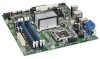
... by 9.60 inches [243.84 millimeters by 243.84 millimeters]) Processor Memory Chipset Support for the following: • Intel® Core™2 Quad processor in an LGA775 socket with a 1066 MHz system bus • Intel® Core™2 Duo processor in an LGA775 socket with a 1333 MHz, 1066 MHz, or... 800 MHz system bus • Intel® Pentium® Dual-Core processor in an LGA775 socket with an 800 MHz system bus • Intel® Celeron® processor 400 sequence in the SPI Flash device) • Support for Advanced Configuration and Power...
... by 9.60 inches [243.84 millimeters by 243.84 millimeters]) Processor Memory Chipset Support for the following: • Intel® Core™2 Quad processor in an LGA775 socket with a 1066 MHz system bus • Intel® Core™2 Duo processor in an LGA775 socket with a 1333 MHz, 1066 MHz, or... 800 MHz system bus • Intel® Pentium® Dual-Core processor in an LGA775 socket with an 800 MHz system bus • Intel® Celeron® processor 400 sequence in the SPI Flash device) • Support for Advanced Configuration and Power...

Product Specification
Page 15
..., or 800 MHz system bus • Intel Pentium Dual-Core processor in an LGA775 socket with an 800 MHz system bus • Intel Celeron processor 400 sequence in an LGA775 socket with a maximum wattage of supported processors. Intel® Desktop Board DQ35JO Desktop Board Support Available... configurations for the Desktop Board DQ35JO Supported processors Chipset information BIOS and driver updates...
..., or 800 MHz system bus • Intel Pentium Dual-Core processor in an LGA775 socket with an 800 MHz system bus • Intel Celeron processor 400 sequence in an LGA775 socket with a maximum wattage of supported processors. Intel® Desktop Board DQ35JO Desktop Board Support Available... configurations for the Desktop Board DQ35JO Supported processors Chipset information BIOS and driver updates...
Product Specification
Page 16
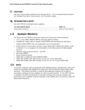
...following restriction: Double-sided DIMMS with DIMMs that support the Serial Presence Detect (SPD) data structure. Intel Desktop Board DQ35JO Technical Product Specification CAUTION Use only the processors listed on the total amount of addressable memory. • Minimum total system memory: 512 MB •... DIMMs with SPD timings of only 5-5-5 (tCL-tRCD-tRP) • DDR2 800 DIMMs with SPD timings of unsupported processors can damage the board, the processor, and the power supply. # INTEGRATOR'S NOTE Use only ATX12V-compliant power supplies. refer to correctly configure the memory ...
...following restriction: Double-sided DIMMS with DIMMs that support the Serial Presence Detect (SPD) data structure. Intel Desktop Board DQ35JO Technical Product Specification CAUTION Use only the processors listed on the total amount of addressable memory. • Minimum total system memory: 512 MB •... DIMMs with SPD timings of only 5-5-5 (tCL-tRCD-tRP) • DDR2 800 DIMMs with SPD timings of unsupported processors can damage the board, the processor, and the power supply. # INTEGRATOR'S NOTE Use only ATX12V-compliant power supplies. refer to correctly configure the memory ...

Product Specification
Page 22
...bus supporting host and target throttling and transfer rates of the Parallel ATA IDE connector Refer to Figure 11, page 45 22 Intel Desktop Board DQ35JO Technical Product Specification NOTE Many Serial ATA drives use new low-voltage power connectors and require adapters or power ... page 45 1.6.3.2 Serial ATA RAID The DQ35JO Desktop Board supports the following modes: • Programmed I/O (PIO): processor controls data transfer. • 8237-style DMA: DMA offloads the processor, supporting transfer rates of up to 16 MB/sec. • Ultra DMA: DMA protocol on IDE bus supporting ...
...bus supporting host and target throttling and transfer rates of the Parallel ATA IDE connector Refer to Figure 11, page 45 22 Intel Desktop Board DQ35JO Technical Product Specification NOTE Many Serial ATA drives use new low-voltage power connectors and require adapters or power ... page 45 1.6.3.2 Serial ATA RAID The DQ35JO Desktop Board supports the following modes: • Programmed I/O (PIO): processor controls data transfer. • 8237-style DMA: DMA offloads the processor, supporting transfer rates of up to 16 MB/sec. • Ultra DMA: DMA protocol on IDE bus supporting ...

Product Specification
Page 30
...the fans on the chassis that detects if the chassis cover is in the processor, 82Q35 GMCH, and 82801IDO ICH9DO • Power supply monitoring of the hardware monitoring and fan control include: • Intel Quiet System Technology, delivering acoustically-optimized thermal management • Fan speed control ... header Refer to Figure 11, page 45 30 When the chassis cover is removed, the mechanical switch is removed. Intel Desktop Board DQ35JO Technical Product Specification 1.13 Hardware Management Subsystem The hardware management features enable the board to be implemented using...
...the fans on the chassis that detects if the chassis cover is in the processor, 82Q35 GMCH, and 82801IDO ICH9DO • Power supply monitoring of the hardware monitoring and fan control include: • Intel Quiet System Technology, delivering acoustically-optimized thermal management • Fan speed control ... header Refer to Figure 11, page 45 30 When the chassis cover is removed, the mechanical switch is removed. Intel Desktop Board DQ35JO Technical Product Specification 1.13 Hardware Management Subsystem The hardware management features enable the board to be implemented using...

Product Specification
Page 31
The GMCH thermal sensor will display 66 °C until the temperature rises above this point. 31 Product Description 1.13.4 Thermal Monitoring Figure 6 shows the locations of the thermal sensors and fan headers. Item A B C D E F G Description Rear chassis fan Thermal diode, located on the GMCH die Thermal diode, located on processor die Remote thermal sensor Processor fan Thermal diode, located on the ICH9DO die Front chassis fan Figure 6. Thermal Sensors and Fan Headers NOTE The minimum thermal reporting threshold for the GMCH is 66 °C.
The GMCH thermal sensor will display 66 °C until the temperature rises above this point. 31 Product Description 1.13.4 Thermal Monitoring Figure 6 shows the locations of the thermal sensors and fan headers. Item A B C D E F G Description Rear chassis fan Thermal diode, located on the GMCH die Thermal diode, located on processor die Remote thermal sensor Processor fan Thermal diode, located on the ICH9DO die Front chassis fan Figure 6. Thermal Sensors and Fan Headers NOTE The minimum thermal reporting threshold for the GMCH is 66 °C.

Product Specification
Page 33
... States States Device States Targeted System Power (Note 1) G0 - working state S0 - Processor stopped C1 - AC power is disconnected from applications and user settings to put the system as a whole into a low-power state. Context not saved. no ...
... States States Device States Targeted System Power (Note 1) G0 - working state S0 - Processor stopped C1 - AC power is disconnected from applications and user settings to put the system as a whole into a low-power state. Context not saved. no ...

Product Specification
Page 36
...Management Engine Wake-on-LAN The board supports waking the Intel® Management Engine over the network. Failure to provide adequate standby current when implementing LAN wake capabilities can be enabled in the S3, S4, or S5 state. • The processor fan header is off as follows: • The ...fans are on the LAN implementation, the board supports LAN wake capabilities with ACPI in a low power state until a management console alert requests Intel AMT functionality. 36 The LAN subsystem PCI bus ...
...Management Engine Wake-on-LAN The board supports waking the Intel® Management Engine over the network. Failure to provide adequate standby current when implementing LAN wake capabilities can be enabled in the S3, S4, or S5 state. • The processor fan header is off as follows: • The ...fans are on the LAN implementation, the board supports LAN wake capabilities with ACPI in a low power state until a management console alert requests Intel AMT functionality. 36 The LAN subsystem PCI bus ...

Product Specification
Page 48
.... ⎯ The SMBus data line is bus master capable. • SMBus signals are routed to pin A41. 48 Intel Desktop Board DQ35JO Technical Product Specification Table 17. Note the following add-in card connector. Processor (4-Pin) Fan Header Pin Signal Name 1 Ground 2 +12 V 3 FAN_TACH 4 FAN_CONTROL 2.2.2.2 Add-in Card Connectors The board has...
.... ⎯ The SMBus data line is bus master capable. • SMBus signals are routed to pin A41. 48 Intel Desktop Board DQ35JO Technical Product Specification Table 17. Note the following add-in card connector. Processor (4-Pin) Fan Header Pin Signal Name 1 Ground 2 +12 V 3 FAN_TACH 4 FAN_CONTROL 2.2.2.2 Add-in Card Connectors The board has...
Product Specification
Page 49
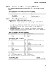
...of the main power connector, leaving pins 11, 12, 23, and 24 unconnected. • Processor core power - This connector provides power directly to the processor voltage regulator and must always be unconnected. Failure to Section 2.5.1on page 55 49 Main Power... x 10 connectors previously used . a 2 x 12 connector. For information about Power supply considerations Refer to do so will be used on Intel Desktop boards. a 2 x 2 connector. Processor Core Power Connector Pin Signal Name 1 Ground 3 +12 V Pin Signal Name 2 Ground 4 +12 V Table 22. Overview of BIOS ...
...of the main power connector, leaving pins 11, 12, 23, and 24 unconnected. • Processor core power - This connector provides power directly to the processor voltage regulator and must always be unconnected. Failure to Section 2.5.1on page 55 49 Main Power... x 10 connectors previously used . a 2 x 12 connector. For information about Power supply considerations Refer to do so will be used on Intel Desktop boards. a 2 x 2 connector. Processor Core Power Connector Pin Signal Name 1 Ground 3 +12 V Pin Signal Name 2 Ground 4 +12 V Table 22. Overview of BIOS ...

Product Specification
Page 53
... move the jumper with the power on BIOS recovery. 53 Location of the jumper block. The maintenance menu is powered-up, the BIOS compares the processor version and the microcode version in the BIOS and reports if the two match. Figure 15 shows the location of the Jumper Block Table 26...
... move the jumper with the power on BIOS recovery. 53 Location of the jumper block. The maintenance menu is powered-up, the BIOS compares the processor version and the microcode version in the BIOS and reports if the two match. Figure 15 shows the location of the Jumper Block Table 26...

Product Specification
Page 55
...of the +5 VSB line • All timing parameters • All voltage tolerances For example, for a system consisting of a supported 65 W processor (see Section 1.4 on page 15 for a list of standby current required depends on configurations chosen by the integrator. Recommended Power Supply Current Values... power supply Refer to http://support.intel.com/support/motherboards/desk top/sb/CS-026472.htm 2.5.2 Fan Header Current Capability CAUTION The processor fan must be connected to the processor fan header, not to a chassis fan header. Connecting the processor fan to a chassis fan header ...
...of the +5 VSB line • All timing parameters • All voltage tolerances For example, for a system consisting of a supported 65 W processor (see Section 1.4 on page 15 for a list of standby current required depends on configurations chosen by the integrator. Recommended Power Supply Current Values... power supply Refer to http://support.intel.com/support/motherboards/desk top/sb/CS-026472.htm 2.5.2 Fan Header Current Capability CAUTION The processor fan must be connected to the processor fan header, not to a chassis fan header. Connecting the processor fan to a chassis fan header ...

Product Specification
Page 56
... current draw for add-in boards for determining the adequacy of 38 oC at the processor fan inlet is designed to exceed their maximum case temperature and malfunction. Intel Desktop Board DQ35JO Technical Product Specification Table 28 lists the current capability of both the... performance. CAUTION Ensure that provides omni-directional airflow to maintain required airflow across the processor voltage regulator area. For a list of chassis that merely following website: http://developer.intel.com/design/motherbd/cooling.htm All responsibility for a fully loaded board (all three ...
... current draw for add-in boards for determining the adequacy of 38 oC at the processor fan inlet is designed to exceed their maximum case temperature and malfunction. Intel Desktop Board DQ35JO Technical Product Specification Table 28 lists the current capability of both the... performance. CAUTION Ensure that provides omni-directional airflow to maintain required airflow across the processor voltage regulator area. For a list of chassis that merely following website: http://developer.intel.com/design/motherbd/cooling.htm All responsibility for a fully loaded board (all three ...

Product Specification
Page 57
... of up to 85 oC in damage to the voltage regulator circuit. Maximum case temperatures are sensitive to thermal changes. Item A B C D Description Processor voltage regulator area Processor Intel 82Q35 GMCH Intel 82801IDO ICH9DO Figure 17. The operating temperature, current load, or operating frequency could affect case temperatures. Overview of BIOS Features CAUTION Ensure that...
... of up to 85 oC in damage to the voltage regulator circuit. Maximum case temperatures are sensitive to thermal changes. Item A B C D Description Processor voltage regulator area Processor Intel 82Q35 GMCH Intel 82801IDO ICH9DO Figure 17. The operating temperature, current load, or operating frequency could affect case temperatures. Overview of BIOS Features CAUTION Ensure that...

Product Specification
Page 58
...specifications for Components Component Maximum Case Temperature Processor For processor case temperature, see processor datasheets and processor specification updates Intel 82Q35 GMCH Intel 82801IDO ICH9DO 97 oC (under bias) 92 oC (under bias) For information about Processor datasheets and specification updates Refer to Section...40 °C to +70 °C Operating 0 °C to estimate repair rates and spare parts requirements. Intel Desktop Board DQ35JO Technical Product Specification Table 29. The MTBF prediction is calculated using component and subassembly random failure ...
...specifications for Components Component Maximum Case Temperature Processor For processor case temperature, see processor datasheets and processor specification updates Intel 82Q35 GMCH Intel 82801IDO ICH9DO 97 oC (under bias) 92 oC (under bias) For information about Processor datasheets and specification updates Refer to Section...40 °C to +70 °C Operating 0 °C to estimate repair rates and spare parts requirements. Intel Desktop Board DQ35JO Technical Product Specification Table 29. The MTBF prediction is calculated using component and subassembly random failure ...

Product Specification
Page 60
... or selects the submenu Load the default configuration values for the Intel Management Engine and Intel Active Management Technology Saves or discards changes to configure the system. BIOS Setup Program Menu Bar Maintenance Clears passwords and displays processor information Main Advanced Security Displays processor and memory configuretion Configures advanced features available through the chipset...
... or selects the submenu Load the default configuration values for the Intel Management Engine and Intel Active Management Technology Saves or discards changes to configure the system. BIOS Setup Program Menu Bar Maintenance Clears passwords and displays processor information Main Advanced Security Displays processor and memory configuretion Configures advanced features available through the chipset...

Product Specification
Page 61
... BIOS revision level • Fixed-system data, such as peripherals, serial numbers, and asset tags • Resource data, such as memory size, cache size, and processor speed • Dynamic data, such as an ATAPI master device. To take advantage of SMBIOS is a Desktop Management Interface (DMI) compliant method for obtaining the...
... BIOS revision level • Fixed-system data, such as peripherals, serial numbers, and asset tags • Resource data, such as memory size, cache size, and processor speed • Dynamic data, such as an ATAPI master device. To take advantage of SMBIOS is a Desktop Management Interface (DMI) compliant method for obtaining the...


