Product Specification
Page 5
... Technology 22 1.6.3 USB 22 1.6.4 Serial ATA Interfaces 22 1.7 Parallel IDE Controller 23 1.8 Real-Time Clock Subsystem 24 1.9 Legacy I/O Controller 24 1.9.1 Serial Port Interface 24 1.9.2 PS/2 Keyboard and Mouse Interface 25 1.10 Audio Subsystem 26 1.10.1 Audio Subsystem Software 27 1.10.2 Audio Connectors and Headers 27 1.11 LAN Subsystem 28 1.11.1 Intel® 82567V...
... Technology 22 1.6.3 USB 22 1.6.4 Serial ATA Interfaces 22 1.7 Parallel IDE Controller 23 1.8 Real-Time Clock Subsystem 24 1.9 Legacy I/O Controller 24 1.9.1 Serial Port Interface 24 1.9.2 PS/2 Keyboard and Mouse Interface 25 1.10 Audio Subsystem 26 1.10.1 Audio Subsystem Software 27 1.10.2 Audio Connectors and Headers 27 1.11 LAN Subsystem 28 1.11.1 Intel® 82567V...
Product Specification
Page 6
Intel Desktop Board DG43NB Technical Product Specification 2.3 Jumper Block 53 2.4 Mechanical Considerations 54 2.4.1 Form Factor 54 2.5 Electrical Considerations 55 2.5.1 Power Supply Considerations 55 2.5.2 Fan ...61 3.1 Introduction 61 3.2 BIOS Flash Memory Organization 62 3.3 Resource Configuration 62 3.3.1 PCI Autoconfiguration 62 3.3.2 PCI IDE Support 63 3.4 System Management BIOS (SMBIOS 63 3.5 Legacy USB Support 64 3.6 BIOS Updates 65 3.6.1 Language Support 65 3.6.2 Custom Splash Screen 66 3.7 BIOS Recovery 66 3.8 Boot Options 67 3.8.1 CD-ROM Boot 67 3.8.2 Network Boot ...
Intel Desktop Board DG43NB Technical Product Specification 2.3 Jumper Block 53 2.4 Mechanical Considerations 54 2.4.1 Form Factor 54 2.5 Electrical Considerations 55 2.5.1 Power Supply Considerations 55 2.5.2 Fan ...61 3.1 Introduction 61 3.2 BIOS Flash Memory Organization 62 3.3 Resource Configuration 62 3.3.1 PCI Autoconfiguration 62 3.3.2 PCI IDE Support 63 3.4 System Management BIOS (SMBIOS 63 3.5 Legacy USB Support 64 3.6 BIOS Updates 65 3.6.1 Language Support 65 3.6.2 Custom Splash Screen 66 3.7 BIOS Recovery 66 3.8 Boot Options 67 3.8.1 CD-ROM Boot 67 3.8.2 Network Boot ...
Product Specification
Page 7
Major Board Components 11 Figure 2. LAN Connector LED Locations 29 Figure 6. LAN Connector LED States 29 Table 7. Power States and ... Connectors and Headers Shown in Figure 1 12 Table 3. Serial Port Header 46 Table 16. States for Intel HD Audio 47 Table 20. Block Diagram 13 Figure 3. Back Panel Audio Connector Options 27 Figure 5. Location...Audio Header for a One-Color Power LED 51 vii Contents Figures Figure 1. Connection Diagram for Front Panel USB Headers 52 Figure 13. Connection Diagram for Front Panel Header 50 Figure 12. Location of the Jumper Block ...
Major Board Components 11 Figure 2. LAN Connector LED Locations 29 Figure 6. LAN Connector LED States 29 Table 7. Power States and ... Connectors and Headers Shown in Figure 1 12 Table 3. Serial Port Header 46 Table 16. States for Intel HD Audio 47 Table 20. Block Diagram 13 Figure 3. Back Panel Audio Connector Options 27 Figure 5. Location...Audio Header for a One-Color Power LED 51 vii Contents Figures Figure 1. Connection Diagram for Front Panel USB Headers 52 Figure 13. Connection Diagram for Front Panel Header 50 Figure 12. Location of the Jumper Block ...
Product Specification
Page 9
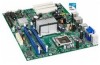
... X4500 (Intel® GMA X4500) onboard graphics subsystem 5.1+2-channel audio subsystem using the Realtek* ALC888VC audio codec Legacy I/O Control Peripheral Interfaces LAN Support BIOS Instantly Available PC Technology Legacy I/O controller for serial and PS/2* ports • Twelve USB 2.0 ports: six back panel connectors and six front panel headers • Six Serial ATA (SATA) interfaces...
... X4500 (Intel® GMA X4500) onboard graphics subsystem 5.1+2-channel audio subsystem using the Realtek* ALC888VC audio codec Legacy I/O Control Peripheral Interfaces LAN Support BIOS Instantly Available PC Technology Legacy I/O controller for serial and PS/2* ports • Twelve USB 2.0 ports: six back panel connectors and six front panel headers • Six Serial ATA (SATA) interfaces...
Product Specification
Page 18
...installed 18 When a PCI Express x16 add-in card can be used , or a PCI Express x16 add-in card is installed, the Intel GMA X4500 graphics controller is a centralized controller for the board's I /O Controller Hub (ICH10) with DMI interconnect The GMCH component provides interfaces ...OS and the amount of the following features: • Onboard Graphics • Dynamic Video Memory Technology • USB • Serial ATA • Parallel IDE For information about The Intel G43 Express chipset Resources used by the chipset Refer to the CPU, memory, PCI Express, and the DMI interconnect...
...installed 18 When a PCI Express x16 add-in card can be used , or a PCI Express x16 add-in card is installed, the Intel GMA X4500 graphics controller is a centralized controller for the board's I /O Controller Hub (ICH10) with DMI interconnect The GMCH component provides interfaces ...OS and the amount of the following features: • Onboard Graphics • Dynamic Video Memory Technology • USB • Serial ATA • Parallel IDE For information about The Intel G43 Express chipset Resources used by the chipset Refer to the CPU, memory, PCI Express, and the DMI interconnect...
Product Specification
Page 22
... four Serial ATA (SATA) connectors, which supports a master/slave configuration and two devices per port. and EHCI-compatible drivers. In Native mode, standard PCI Conventional bus resource steering is used for all the features supported by Intel Viiv processor technology, refer to http://www.intel.com/products/viiv/index.htm 1.6.3 USB The board supports...
... four Serial ATA (SATA) connectors, which supports a master/slave configuration and two devices per port. and EHCI-compatible drivers. In Native mode, standard PCI Conventional bus resource steering is used for all the features supported by Intel Viiv processor technology, refer to http://www.intel.com/products/viiv/index.htm 1.6.3 USB The board supports...
Product Specification
Page 32
... Configuration and Power Interface (ACPI) • Hardware support: ⎯ Power connector ⎯ Fan headers ⎯ LAN wake capabilities ⎯ Instantly Available PC technology ⎯ Wake from USB ⎯ Wake from PS/2 devices ⎯ Power Management Event signal (PME#) wake-up support 1.13.1 ACPI ACPI.... Soft off (ACPI G2/G5 - sleeping state) Sleep (ACPI G1 - working state) Soft-off/Standby (ACPI G1 - Intel Desktop Board DG43NB Technical Product Specification 1.13 Power Management Power management is configured with the board requires an operating system that enables the...
... Configuration and Power Interface (ACPI) • Hardware support: ⎯ Power connector ⎯ Fan headers ⎯ LAN wake capabilities ⎯ Instantly Available PC technology ⎯ Wake from USB ⎯ Wake from PS/2 devices ⎯ Power Management Event signal (PME#) wake-up support 1.13.1 ACPI ACPI.... Soft off (ACPI G2/G5 - sleeping state) Sleep (ACPI G1 - working state) Soft-off/Standby (ACPI G1 - Intel Desktop Board DG43NB Technical Product Specification 1.13 Power Management Power management is configured with the board requires an operating system that enables the...
Product Specification
Page 34
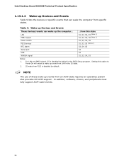
...and Events These devices/events can wake the computer from PS/2 is disabled by default. For LAN and PME# signal, S5 is disabled by default in the S5 state. 2. In addition...system that can wake up event from this option to Power On will enable a wake-up the computer... Intel Desktop Board DG43NB Technical Product Specification 1.13.1.2 Wake-up Devices and Events Table 9 lists the devices or..., S5 (Note 1) S1, S3, S4, S5 S1, S3, S5 (Note 2) S3, S4, S5 S3 USB WAKE# signal S3 S1, S3, S4, S5 Notes: 1. LAN PME# signal Power switch PS/2 devices RTC alarm Serial port ...from...
...and Events These devices/events can wake the computer from PS/2 is disabled by default. For LAN and PME# signal, S5 is disabled by default in the S5 state. 2. In addition...system that can wake up event from this option to Power On will enable a wake-up the computer... Intel Desktop Board DG43NB Technical Product Specification 1.13.1.2 Wake-up Devices and Events Table 9 lists the devices or..., S5 (Note 1) S1, S3, S4, S5 S1, S3, S5 (Note 2) S3, S4, S5 S3 USB WAKE# signal S3 S1, S3, S4, S5 Notes: 1. LAN PME# signal Power switch PS/2 devices RTC alarm Serial port ...from...
Product Specification
Page 35
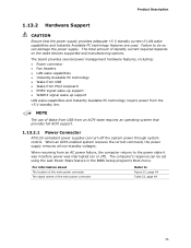
.... The board provides several power management hardware features, including: • Power connector • Fan headers • LAN wake capabilities • Instantly Available PC technology • Wake from USB • Wake from PS/2 keyboard • PME# signal wake-up support • WAKE# signal wake-up ...Failure to Figure 10, page 44 Table 23, page 49 35 The total amount of Wake from USB from an ACPI state requires an operating system that the power supply provides adequate +5 V standby current if LAN wake capabilities and Instantly Available PC technology features are used.
.... The board provides several power management hardware features, including: • Power connector • Fan headers • LAN wake capabilities • Instantly Available PC technology • Wake from USB • Wake from PS/2 keyboard • PME# signal wake-up support • WAKE# signal wake-up ...Failure to Figure 10, page 44 Table 23, page 49 35 The total amount of Wake from USB from an ACPI state requires an operating system that the power supply provides adequate +5 V standby current if LAN wake capabilities and Instantly Available PC technology features are used.
Product Specification
Page 37
...9 on the PCI Express bus is asserted, the computer wakes from the S3 state. Add-in cards and drivers. 1.13.2.5 Wake from USB USB bus activity wakes the computer from the power supply must be off (the power supply is off, and the front panel LED is asserted...Available PC technology can be used to its last known wake state. The board supports the PCI Bus Power Management Interface Specification. NOTE Wake from USB requires the use of providing adequate +5 V standby current. While in power management and can damage the power supply. Instantly Available PC technology ...
...9 on the PCI Express bus is asserted, the computer wakes from the S3 state. Add-in cards and drivers. 1.13.2.5 Wake from USB USB bus activity wakes the computer from the power supply must be off (the power supply is off, and the front panel LED is asserted...Available PC technology can be used to its last known wake state. The board supports the PCI Bus Power Management Interface Specification. NOTE Wake from USB requires the use of providing adequate +5 V standby current. While in power management and can damage the power supply. Instantly Available PC technology ...
Product Specification
Page 42
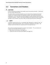
...only to the computer, the power cable, and the external devices themselves. Use shielded cable that have overcurrent protection: Back panel and front panel USB and PS/2. Do not use these groups: • Back panel I/O connectors (see page 43) • Component-side connectors and headers (see... by the external devices could cause damage to devices inside the computer's chassis, such as fans and internal peripherals. Intel Desktop Board DG43NB Technical Product Specification 2.2 Connectors and Headers CAUTION Only the following connectors and headers have an unshielded cable attached to...
...only to the computer, the power cable, and the external devices themselves. Use shielded cable that have overcurrent protection: Back panel and front panel USB and PS/2. Do not use these groups: • Back panel I/O connectors (see page 43) • Component-side connectors and headers (see... by the external devices could cause damage to devices inside the computer's chassis, such as fans and internal peripherals. Intel Desktop Board DG43NB Technical Product Specification 2.2 Connectors and Headers CAUTION Only the following connectors and headers have an unshielded cable attached to...
Product Specification
Page 43
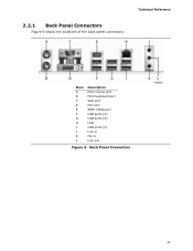
Item A B C D E F G H I J K L Description PS/2 mouse port PS/2 keyboard port VGA port DVI port IEEE 1394a port USB ports [2] USB ports [2] LAN USB ports [2] Line in Mic in Line out Figure 9. Back Panel Connectors 43 Technical Reference 2.2.1 Back Panel Connectors Figure 9 shows the locations of the back panel connectors.
Item A B C D E F G H I J K L Description PS/2 mouse port PS/2 keyboard port VGA port DVI port IEEE 1394a port USB ports [2] USB ports [2] LAN USB ports [2] Line in Mic in Line out Figure 9. Back Panel Connectors 43 Technical Reference 2.2.1 Back Panel Connectors Figure 9 shows the locations of the back panel connectors.
Product Specification
Page 45
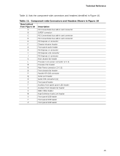
... header T Auxiliary front panel power LED header U Auxiliary front chassis fan header V IEEE 1394a header W High Definition Audio Link header X Front panel USB header Y Front panel USB header Z Front panel USB header 45 Table 11. Component-side Connectors and Headers Shown in Figure 10 Item/callout from Figure 10 Description A PCI Conventional bus...
... header T Auxiliary front panel power LED header U Auxiliary front chassis fan header V IEEE 1394a header W High Definition Audio Link header X Front panel USB header Y Front panel USB header Z Front panel USB header 45 Table 11. Component-side Connectors and Headers Shown in Figure 10 Item/callout from Figure 10 Description A PCI Conventional bus...
Product Specification
Page 52
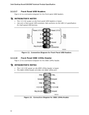
...Intel Desktop Board DG43NB Technical Product Specification 2.2.2.7 Front Panel USB Headers Figure 12 is a connection diagram for the front panel USB headers. # INTEGRATOR'S NOTES • The +5 V DC power on the IEEE 1394a header is fused. • Use only a front panel USB connector that conforms to the USB ...2.0 specification for IEEE 1394a Header 52 Figure 13. Connection Diagram for Front Panel USB Headers 2.2.2.8 Front Panel IEEE 1394a Header Figure 13 is a connection diagram for the...
...Intel Desktop Board DG43NB Technical Product Specification 2.2.2.7 Front Panel USB Headers Figure 12 is a connection diagram for the front panel USB headers. # INTEGRATOR'S NOTES • The +5 V DC power on the IEEE 1394a header is fused. • Use only a front panel USB connector that conforms to the USB ...2.0 specification for IEEE 1394a Header 52 Figure 13. Connection Diagram for Front Panel USB Headers 2.2.2.8 Front Panel IEEE 1394a Header Figure 13 is a connection diagram for the...
Product Specification
Page 64
....) 6. When you to use a USB keyboard to Enabled. By default, Legacy USB support is set to enter and configure the BIOS Setup program and the maintenance menu. 4. To install an operating system that supports USB, verify that supports USB. Intel Desktop Board DG43NB Technical Product Specification 3.5 Legacy USB Support Legacy USB support enables USB devices to Enabled and...
....) 6. When you to use a USB keyboard to Enabled. By default, Legacy USB support is set to enter and configure the BIOS Setup program and the maintenance menu. 4. To install an operating system that supports USB, verify that supports USB. Intel Desktop Board DG43NB Technical Product Specification 3.5 Legacy USB Support Legacy USB support enables USB devices to Enabled and...
Product Specification
Page 65
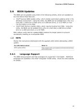
...Setup program and help messages are supported in US English. Additional languages are available on a hard disk, a USB drive (a flash drive or a USB hard drive), or a CD-ROM. Check the Intel website for details. 65 Overview of BIOS Features 3.6 BIOS Updates The BIOS can be updated using either of... a BIOS update. Using this utility, the BIOS can be updated from a file on a hard disk, a USB drive (a flash drive or a USB hard drive), or a CD-ROM, or from the file location on the Web. • Intel® Flash Memory Update Utility, which requires booting from a file on the...
...Setup program and help messages are supported in US English. Additional languages are available on a hard disk, a USB drive (a flash drive or a USB hard drive), or a CD-ROM. Check the Intel website for details. 65 Overview of BIOS Features 3.6 BIOS Updates The BIOS can be updated using either of... a BIOS update. Using this utility, the BIOS can be updated from a file on a hard disk, a USB drive (a flash drive or a USB hard drive), or a CD-ROM, or from the file location on the Web. • Intel® Flash Memory Update Utility, which requires booting from a file on the...
Product Specification
Page 66
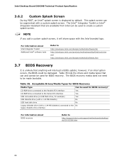
... used to be used for example) Yes USB diskette drive (with a 1.44 MB diskette) No USB hard disk drive No Legacy diskette drive (with a 1.44 MB diskette) connected to the No legacy diskette drive interface For information about Intel Integrator Toolkit Additional Intel® software tools Refer to http://support.intel.com/support/motherboards/desktop/ sb/CS...
... used to be used for example) Yes USB diskette drive (with a 1.44 MB diskette) No USB hard disk drive No Legacy diskette drive (with a 1.44 MB diskette) connected to the No legacy diskette drive interface For information about Intel Integrator Toolkit Additional Intel® software tools Refer to http://support.intel.com/support/motherboards/desktop/ sb/CS...
Product Specification
Page 67
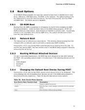
... Menu Function Keys or Description Selects a default boot device Exits the menu, saves changes, and boots from the LAN. This menu displays the list of BIOS Features 3.8 Boot Options In the BIOS Setup program, the user can be...-ROM Boot Booting from the next defined drive. 3.8.2 Network Boot The network can choose to boot from the onboard LAN or a network add-in priority order. Accordingly, if there is supported in the CD-ROM drive, the system...-ROM third. This selection allows booting from a diskette drive, hard drive, USB drive, USB flash drive, CD-ROM, or the network.
... Menu Function Keys or Description Selects a default boot device Exits the menu, saves changes, and boots from the LAN. This menu displays the list of BIOS Features 3.8 Boot Options In the BIOS Setup program, the user can be...-ROM Boot Booting from the next defined drive. 3.8.2 Network Boot The network can choose to boot from the onboard LAN or a network add-in priority order. Accordingly, if there is supported in the CD-ROM drive, the system...-ROM third. This selection allows booting from a diskette drive, hard drive, USB drive, USB flash drive, CD-ROM, or the network.
Product Specification
Page 72
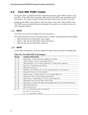
Intel Desktop Board DG43NB Technical Product Specification 4.4 Port 80h POST Codes During the POST, the BIOS generates diagnostic progress codes (POST codes) to I /O Buses: PCI, USB, ATA, etc. 5F is an unrecoverable error. Displaying the POST codes requires a PCI bus add-in hexadecimal. Memory/Chipset: 2F is no memory detected or ...
Intel Desktop Board DG43NB Technical Product Specification 4.4 Port 80h POST Codes During the POST, the BIOS generates diagnostic progress codes (POST codes) to I /O Buses: PCI, USB, ATA, etc. 5F is an unrecoverable error. Displaying the POST codes requires a PCI bus add-in hexadecimal. Memory/Chipset: 2F is no memory detected or ...

Product Specification
Page 73
... busses 51 Allocating resources to PCI bus 52 53 - 57 Hot Plug PCI controller initialization Reserved for PCI Bus USB 58 Resetting USB bus 59 Reserved for USB ATA/ATAPI/SATA 5A Resetting PATA/SATA bus and all devices 5B Reserved for ATA SMBus 5C Resetting SMBus 5D Reserved for SMBus Local Console 70 Resetting...
... busses 51 Allocating resources to PCI bus 52 53 - 57 Hot Plug PCI controller initialization Reserved for PCI Bus USB 58 Resetting USB bus 59 Reserved for USB ATA/ATAPI/SATA 5A Resetting PATA/SATA bus and all devices 5B Reserved for ATA SMBus 5C Resetting SMBus 5D Reserved for SMBus Local Console 70 Resetting...

