
Product Specification
Page 2
... materials and information does not provide any license, express or implied, by estoppel or otherwise, to only the standard Intel® Desktop Board DG33BU with BIOS identifier DPP3510A.86A. Copies of documents and other Intel literature, may make changes to the presented subject matter. Revision History Revision -001 Revision History First release of...
... materials and information does not provide any license, express or implied, by estoppel or otherwise, to only the standard Intel® Desktop Board DG33BU with BIOS identifier DPP3510A.86A. Copies of documents and other Intel literature, may make changes to the presented subject matter. Revision History Revision -001 Revision History First release of...

Product Specification
Page 3
...Board DG33BU and its components to the vendors, system integrators, and other engineers and technicians who need this level of the BIOS error messages, beep codes, and POST codes Regulatory compliance and battery disposal information Typographical Conventions This section contains information about ...may be useful to help you avoid damaging hardware or losing data. iii Intended Audience The TPS is specifically not intended for the Intel® Desktop Board DG33BU. Notes, Cautions, and Warnings NOTE Notes call attention to important information. # INTEGRATOR'S NOTES Integrator's notes ...
...Board DG33BU and its components to the vendors, system integrators, and other engineers and technicians who need this level of the BIOS error messages, beep codes, and POST codes Regulatory compliance and battery disposal information Typographical Conventions This section contains information about ...may be useful to help you avoid damaging hardware or losing data. iii Intended Audience The TPS is specifically not intended for the Intel® Desktop Board DG33BU. Notes, Cautions, and Warnings NOTE Notes call attention to important information. # INTEGRATOR'S NOTES Integrator's notes ...
Product Specification
Page 6
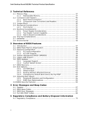
Intel Desktop Board DG33BU Technical Product Specification 2 Technical Reference 2.1 Memory Map 37 2.1.1 Addressable Memory 37 2.2 Connectors and Headers 40 2.2.1 Back Panel Connectors 41 2.2.2 Component-...the Default Boot Device During POST 63 3.9 Adjusting Boot Speed 64 3.9.1 Peripheral Selection and Configuration 64 3.9.2 BIOS Boot Optimizations 64 3.10 BIOS Security Features 65 4 Error Messages and Beep Codes 4.1 Speaker 67 4.2 BIOS Beep Codes 67 4.3 BIOS Error Messages 67 4.4 Port 80h POST Codes 68 5 Regulatory Compliance and Battery Disposal Information 5.1 Regulatory ...
Intel Desktop Board DG33BU Technical Product Specification 2 Technical Reference 2.1 Memory Map 37 2.1.1 Addressable Memory 37 2.2 Connectors and Headers 40 2.2.1 Back Panel Connectors 41 2.2.2 Component-...the Default Boot Device During POST 63 3.9 Adjusting Boot Speed 64 3.9.1 Peripheral Selection and Configuration 64 3.9.2 BIOS Boot Optimizations 64 3.10 BIOS Security Features 65 4 Error Messages and Beep Codes 4.1 Speaker 67 4.2 BIOS Beep Codes 67 4.3 BIOS Error Messages 67 4.4 Port 80h POST Codes 68 5 Regulatory Compliance and Battery Disposal Information 5.1 Regulatory ...
Product Specification
Page 8
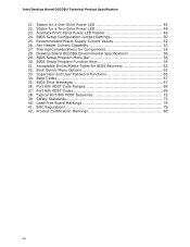
...for a Two-Color Power LED 48 23. Lead-Free Board Markings 78 41. States for BIOS Recovery 62 32. Boot Device Menu Options 63 33. Thermal Considerations for a One-Color Power LED 48 22. BIOS Error Messages 67 36. Typical Port 80h POST Sequence 72 39. Supervisor and User Password ...42. States for Components 55 28. Port 80h POST Codes 69 38. Safety Standards 73 40. Auxiliary Front Panel Power LED Header 48 24. BIOS Setup Program Menu Bar 58 30. Intel Desktop Board DG33BU Technical Product Specification 21. BIOS Setup Program Function Keys 58 31.
...for a Two-Color Power LED 48 23. Lead-Free Board Markings 78 41. States for BIOS Recovery 62 32. Boot Device Menu Options 63 33. Thermal Considerations for a One-Color Power LED 48 22. BIOS Error Messages 67 36. Typical Port 80h POST Sequence 72 39. Supervisor and User Password ...42. States for Components 55 28. Port 80h POST Codes 69 38. Safety Standards 73 40. Auxiliary Front Panel Power LED Header 48 24. BIOS Setup Program Menu Bar 58 30. Intel Desktop Board DG33BU Technical Product Specification 21. BIOS Setup Program Function Keys 58 31.
Product Specification
Page 10
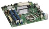
...; One serial port header (may require specialized chassis or cable for use) Gigabit (10/100/1000 Mbits/sec) LAN subsystem using the Intel® 82566DC Gigabit Ethernet Controller • Intel® BIOS (resident in the SPI Flash device) • Support for Advanced Configuration and Power Interface (ACPI), Plug and Play, and SMBIOS •...
...; One serial port header (may require specialized chassis or cable for use) Gigabit (10/100/1000 Mbits/sec) LAN subsystem using the Intel® 82566DC Gigabit Ethernet Controller • Intel® BIOS (resident in the SPI Flash device) • Support for Advanced Configuration and Power Interface (ACPI), Plug and Play, and SMBIOS •...
Product Specification
Page 15
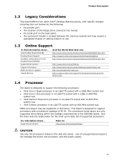
...Use of unsupported processors can damage the board, the processor, and the power supply. 15 See the Intel web site listed below for the Desktop Board DG33BU Supported processors Chipset information BIOS and driver updates Tested Memory Visit this World Wide Web site: http://www....intel.com/products/motherboard/DG33BU/index.htm http://support.intel.com/support/motherboards/desktop http://www.intel.com/products/motherboard/DG33BU/index.htm http://www.intel.com/go /findcpu ...
...Use of unsupported processors can damage the board, the processor, and the power supply. 15 See the Intel web site listed below for the Desktop Board DG33BU Supported processors Chipset information BIOS and driver updates Tested Memory Visit this World Wide Web site: http://www....intel.com/products/motherboard/DG33BU/index.htm http://support.intel.com/support/motherboards/desktop http://www.intel.com/products/motherboard/DG33BU/index.htm http://www.intel.com/go /findcpu ...
Product Specification
Page 16
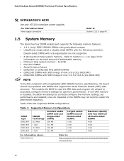
...or the DIMMs may be populated with x16 organization are not supported. • 8 GB maximum total system memory. This enables the BIOS to read the SPD data and program the chipset to Section 2.2.2.4, page 46 1.5 System Memory The board has four DIMM sockets and...-sided DIMMs with DIMMs that support the Serial Presence Detect (SPD) data structure. Refer to : http://support.intel.com/support/motherboards/desktop/sb/ CS-025414.htm 16 Intel Desktop Board DG33BU Technical Product Specification # INTEGRATOR'S NOTE Use only ATX12V-compliant power supplies. For information about ......
...or the DIMMs may be populated with x16 organization are not supported. • 8 GB maximum total system memory. This enables the BIOS to read the SPD data and program the chipset to Section 2.2.2.4, page 46 1.5 System Memory The board has four DIMM sockets and...-sided DIMMs with DIMMs that support the Serial Presence Detect (SPD) data structure. Refer to : http://support.intel.com/support/motherboards/desktop/sb/ CS-025414.htm 16 Intel Desktop Board DG33BU Technical Product Specification # INTEGRATOR'S NOTE Use only ATX12V-compliant power supplies. For information about ......
Product Specification
Page 20
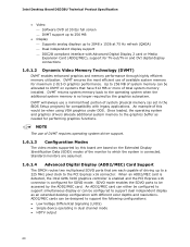
...can either be configured to support simultaneous display or can be configured to the graphics buffer as an extended desktop configuration with legacy applications. Intel Desktop Board DG33BU Technical Product Specification • Video ⎯ Software DVD at 75 Hz refresh (QXGA) ⎯ Dual independent display ...or Media Expansion Card (ADD2/MEC), support for TV-out/TV-in the BIOS Setup program) for compatibility with different color depths and resolutions. When an ADD2/MEC card is detected, the Intel GMA 3100 graphics controller is enabled and the PCI Express x16 connector is no...
...can either be configured to support simultaneous display or can be configured to the graphics buffer as an extended desktop configuration with legacy applications. Intel Desktop Board DG33BU Technical Product Specification • Video ⎯ Software DVD at 75 Hz refresh (QXGA) ⎯ Dual independent display ...or Media Expansion Card (ADD2/MEC), support for TV-out/TV-in the BIOS Setup program) for compatibility with different color depths and resolutions. When an ADD2/MEC card is detected, the Intel GMA 3100 graphics controller is enabled and the PCI Express x16 connector is no...

Product Specification
Page 22
... and write transfer rates up to 88 MB/sec. • ATA-133: DMA protocol on IDE bus allows host and target throttling. The BIOS supports Logical Block Addressing (LBA) and Extended Cylinder Head Sector (ECHS) translation modes. The drive reports the transfer rate and translation mode to ...MB/sec. • Ultra DMA: DMA protocol on IDE bus supporting host and target throttling and transfer rates of 100 MB/sec. Intel Desktop Board DG33BU Technical Product Specification NOTE Many Serial ATA drives use new low-voltage power connectors and require adapters or power supplies equipped with...
... and write transfer rates up to 88 MB/sec. • ATA-133: DMA protocol on IDE bus allows host and target throttling. The BIOS supports Logical Block Addressing (LBA) and Extended Cylinder Head Sector (ECHS) translation modes. The drive reports the transfer rate and translation mode to ...MB/sec. • Ultra DMA: DMA protocol on IDE bus supporting host and target throttling and transfer rates of 100 MB/sec. Intel Desktop Board DG33BU Technical Product Specification NOTE Many Serial ATA drives use new low-voltage power connectors and require adapters or power supplies equipped with...

Product Specification
Page 23
...location of the diskette drive connector Refer to ± 13 minutes/year at power-on. When the voltage drops below a certain level, the BIOS Setup program settings stored in , the standby current from the power supply extends the life of the board. Product Description 1.8 Real-Time Clock Subsystem... real-time clock and CMOS memory. The serial port supports data transfers at speeds up event interface • PCI power management support The BIOS Setup program provides configuration options for example, the date and time) might not be loaded into a wall socket, the battery has an ...
...location of the diskette drive connector Refer to ± 13 minutes/year at power-on. When the voltage drops below a certain level, the BIOS Setup program settings stored in , the standby current from the power supply extends the life of the board. Product Description 1.8 Real-Time Clock Subsystem... real-time clock and CMOS memory. The serial port supports data transfers at speeds up event interface • PCI power management support The BIOS Setup program provides configuration options for example, the date and time) might not be loaded into a wall socket, the battery has an ...

Product Specification
Page 32
... Devices and Events Table 8 lists the devices or specific events that provides full ACPI support. Currently Intel Desktop Boards meet the new requirements. LAN PME# signal ...from LAN in the BIOS Setup program. In addition, software, drivers, and peripherals must fully support ACPI wake events. 32...ENERGY STAR requirements and recommended configurations Refer to Power On will enable a wake-up event from this option to http://www.intel.com/go/energystar 1.13.1.3 Wake-up the computer... Wake-up Devices and Events These devices/events can wake the computer from specific states...
... Devices and Events Table 8 lists the devices or specific events that provides full ACPI support. Currently Intel Desktop Boards meet the new requirements. LAN PME# signal ...from LAN in the BIOS Setup program. In addition, software, drivers, and peripherals must fully support ACPI wake events. 32...ENERGY STAR requirements and recommended configurations Refer to Power On will enable a wake-up event from this option to http://www.intel.com/go/energystar 1.13.1.3 Wake-up the computer... Wake-up Devices and Events These devices/events can wake the computer from specific states...

Product Specification
Page 33
... use of the main power connector Refer to do so can be set using the Last Power State feature in before power was in the BIOS Setup program's Boot menu. When an ACPI-enabled system receives the correct command, the power supply removes all non-standby voltages. Product Description 1.13.2 Hardware...
... use of the main power connector Refer to do so can be set using the Last Power State feature in before power was in the BIOS Setup program's Boot menu. When an ACPI-enabled system receives the correct command, the power supply removes all non-standby voltages. Product Description 1.13.2 Hardware...

Product Specification
Page 35
While in BIOS). 1.13.2.8 WAKE# Signal Wake-up device or event, the system quickly returns to wake the computer. Table 8 on page 32 lists the devices and events ...
While in BIOS). 1.13.2.8 WAKE# Signal Wake-up device or event, the system quickly returns to wake the computer. Table 8 on page 32 lists the devices and events ...

Product Specification
Page 37
... Flash), and chipset overhead resides above the top of addressable system memory. These functions include the following: • BIOS/ SPI Flash (8 Mbits) • Local APIC (19 MB) • Digital Media Interface (40 MB) • Front side bus interrupts (17 MB) • PCI... is not possible to use all of the installed memory due to system address space being allocated for PCI Conventional bus add-in cards • Intel Management Engine support (6 MB) • Base graphics memory support (1 MB or 8 MB) 37 2 Technical Reference What This Chapter Contains 2.1 Memory Map 37 2.2 ...
... Flash), and chipset overhead resides above the top of addressable system memory. These functions include the following: • BIOS/ SPI Flash (8 Mbits) • Local APIC (19 MB) • Digital Media Interface (40 MB) • Front side bus interrupts (17 MB) • PCI... is not possible to use all of the installed memory due to system address space being allocated for PCI Conventional bus add-in cards • Intel Management Engine support (6 MB) • Base graphics memory support (1 MB or 8 MB) 37 2 Technical Reference What This Chapter Contains 2.1 Memory Map 37 2.2 ...
Product Specification
Page 38
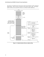
Intel Desktop Board DG33BU Technical Product Specification The amount of installed memory that can be used when there is no overlap...DRAM Range DOS Compatibility Memory Top of the system memory map. All installed system memory can be used will vary based on add-in Card BIOS and Buffer area (128 KB; 16 KB x 8) Standard PCI/ ISA Video Memory (SMM Memory) 128 KB DOS area (640 KB)...visible to the operating system) 1 MB 640 KB 0 MB 0FFFFFH 0F0000H 0EFFFFH 0E0000H 0DFFFFH 0C0000H 0BFFFFH 0A0000H 09FFFFH 00000H Upper BIOS area (64 KB) Lower BIOS area (64 KB; 16 KB x 4) Add-in cards and...
Intel Desktop Board DG33BU Technical Product Specification The amount of installed memory that can be used when there is no overlap...DRAM Range DOS Compatibility Memory Top of the system memory map. All installed system memory can be used will vary based on add-in Card BIOS and Buffer area (128 KB; 16 KB x 8) Standard PCI/ ISA Video Memory (SMM Memory) 128 KB DOS area (640 KB)...visible to the operating system) 1 MB 640 KB 0 MB 0FFFFFH 0F0000H 0EFFFFH 0E0000H 0DFFFFH 0C0000H 0BFFFFH 0A0000H 09FFFFH 00000H Upper BIOS area (64 KB) Lower BIOS area (64 KB; 16 KB x 4) Add-in cards and...

Product Specification
Page 39
... - 9FFFF 80000 - 9FBFF 00000 - 7FFFF Size 8191 MB 64 KB 64 KB 96 KB 160 KB 1 KB 127 KB 512 KB Description Extended memory Runtime BIOS Reserved Potential available high DOS memory (open to the PCI bus). Technical Reference Table 9 lists the system memory map. Video memory and...
... - 9FFFF 80000 - 9FBFF 00000 - 7FFFF Size 8191 MB 64 KB 64 KB 96 KB 160 KB 1 KB 127 KB 512 KB Description Extended memory Runtime BIOS Reserved Potential available high DOS memory (open to the PCI bus). Technical Reference Table 9 lists the system memory map. Video memory and...

Product Specification
Page 50
Intel Desktop Board DG33BU Technical Product Specification 2.3 Jumper Block CAUTION Do not move the jumper with the power on BIOS recovery. 50 Otherwise, the board could be damaged. Figure 13. The maintenance menu is powered-up, the BIOS compares the processor version and the microcode version in the BIOS...reports if the two match. Table 24 lists the jumper settings for booting. BIOS Setup Configuration Jumper Settings Function/Mode Jumper Setting Configuration Normal 1-2 The BIOS uses current configuration information and passwords for the three modes: normal, configure, and...
Intel Desktop Board DG33BU Technical Product Specification 2.3 Jumper Block CAUTION Do not move the jumper with the power on BIOS recovery. 50 Otherwise, the board could be damaged. Figure 13. The maintenance menu is powered-up, the BIOS compares the processor version and the microcode version in the BIOS...reports if the two match. Table 24 lists the jumper settings for booting. BIOS Setup Configuration Jumper Settings Function/Mode Jumper Setting Configuration Normal 1-2 The BIOS uses current configuration information and passwords for the three modes: normal, configure, and...
Product Specification
Page 57
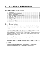
... Memory Organization 58 3.3 Resource Configuration 58 3.4 System Management BIOS (SMBIOS 59 3.5 Legacy USB Support 60 3.6 BIOS Updates 61 3.7 BIOS Recovery 62 3.8 Boot Options 63 3.9 Adjusting Boot Speed 64 3.10 BIOS Security Features 65 3.1 Introduction The board uses an Intel BIOS that is powered-up, the BIOS compares the CPU version and the microcode version in configure mode...
... Memory Organization 58 3.3 Resource Configuration 58 3.4 System Management BIOS (SMBIOS 59 3.5 Legacy USB Support 60 3.6 BIOS Updates 61 3.7 BIOS Recovery 62 3.8 Boot Options 63 3.9 Adjusting Boot Speed 64 3.10 BIOS Security Features 65 3.1 Introduction The board uses an Intel BIOS that is powered-up, the BIOS compares the CPU version and the microcode version in configure mode...
Product Specification
Page 58
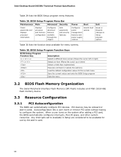
...discards changes to be onboard or add-in cards. Any interrupts set to Available in card. 58 Intel Desktop Board DG33BU Technical Product Specification Table 29 lists the BIOS Setup program menu features. Table 30. Autoconfiguration lets a user insert or remove PCI cards without ... Setup program options Table 30 lists the function keys available for the current menu Save the current values and exits the BIOS Setup program Exits the menu 3.2 BIOS Flash Memory Organization The Serial Peripheral Interface Flash Memory (SPI Flash) includes an 8 Mbit (1024 KB) flash memory ...
...discards changes to be onboard or add-in cards. Any interrupts set to Available in card. 58 Intel Desktop Board DG33BU Technical Product Specification Table 29 lists the BIOS Setup program menu features. Table 30. Autoconfiguration lets a user insert or remove PCI cards without ... Setup program options Table 30 lists the function keys available for the current menu Save the current values and exits the BIOS Setup program Exits the menu 3.2 BIOS Flash Memory Organization The Serial Peripheral Interface Flash Memory (SPI Flash) includes an 8 Mbit (1024 KB) flash memory ...
Product Specification
Page 59
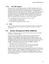
...information. You can obtain the system types, capabilities, operational status, and installation dates for obtaining the SMBIOS information. The BIOS enables applications such as event detection and error logging Non-Plug and Play operating systems require an additional interface for system ...Desktop Management Interface (DMI) compliant method for Logical Block Addressing (LBA) and to an ATAPI CD-ROM drive. 3.4 System Management BIOS (SMBIOS) SMBIOS is the Management Information Format (MIF) database, which contains information about the computing system and its components. The ...
...information. You can obtain the system types, capabilities, operational status, and installation dates for obtaining the SMBIOS information. The BIOS enables applications such as event detection and error logging Non-Plug and Play operating systems require an additional interface for system ...Desktop Management Interface (DMI) compliant method for Logical Block Addressing (LBA) and to an ATAPI CD-ROM drive. 3.4 System Management BIOS (SMBIOS) SMBIOS is the Management Information Format (MIF) database, which contains information about the computing system and its components. The ...


