
Product Specification
Page 5
Contents 1 Product Description 1.1 Overview ...10 1.1.1 Feature Summary 10 1.1.2 Manufacturing Options 11 1.1.3 Board Layout 12 1.1.4 Block Diagram 14 1.2 Online Support ...15 1.3 Processor ...15 1.4 System Memory ...16 1.5 ATI Radeon* Xpress 200 Chipset 17 1.5.1 Graphics Subsystem 17 1.5.2 Firmware Hub (FWH 17 1.5.3 USB ...17 1.5.4 IDE Support 18 1.5.5 Real-Time Clock, ...
Contents 1 Product Description 1.1 Overview ...10 1.1.1 Feature Summary 10 1.1.2 Manufacturing Options 11 1.1.3 Board Layout 12 1.1.4 Block Diagram 14 1.2 Online Support ...15 1.3 Processor ...15 1.4 System Memory ...16 1.5 ATI Radeon* Xpress 200 Chipset 17 1.5.1 Graphics Subsystem 17 1.5.2 Firmware Hub (FWH 17 1.5.3 USB ...17 1.5.4 IDE Support 18 1.5.5 Real-Time Clock, ...

Product Specification
Page 7
.... Back Panel Connectors 43 7. Connection Diagram for a Two-Color Power LED 49 28. Location of Pressing the Power Switch 30 7. Processor Heatsink for High Definition Audio Subsystem...... 27 4. Localized High Temperature Zones 57 Tables 1. DMA Channels ...38 11. PCI Interrupt Routing Map...11 3. PCI Configuration Space Map 41 14. I /O Map ...39 12. System Memory Map 37 10. Chassis Intrusion Connector 46 19. Processor Fan Connector 46 21. Wake-up Devices and Events 31 9. Feature Summary ...10 2. Location of the Standby Power Indicator LED 35 6. Connection...
.... Back Panel Connectors 43 7. Connection Diagram for a Two-Color Power LED 49 28. Location of Pressing the Power Switch 30 7. Processor Heatsink for High Definition Audio Subsystem...... 27 4. Localized High Temperature Zones 57 Tables 1. DMA Channels ...38 11. PCI Interrupt Routing Map...11 3. PCI Configuration Space Map 41 14. I /O Map ...39 12. System Memory Map 37 10. Chassis Intrusion Connector 46 19. Processor Fan Connector 46 21. Wake-up Devices and Events 31 9. Feature Summary ...10 2. Location of the Standby Power Indicator LED 35 6. Connection...

Product Specification
Page 9
1 Product Description What This Chapter Contains 1.1 Overview ...10 1.2 Online Support ...15 1.3 Processor ...15 1.4 System Memory ...16 1.5 ATI Radeon* Xpress 200 Chipset 17 1.6 PCI Express* Connectors 24 1.7 Legacy I/O Controller 24 1.8 High Definition Audio Subsystem 26 1.9 LAN Subsystem ...28 1.10 Hardware Management Subsystem 29 1.11 Power Management ...29 9
1 Product Description What This Chapter Contains 1.1 Overview ...10 1.2 Online Support ...15 1.3 Processor ...15 1.4 System Memory ...16 1.5 ATI Radeon* Xpress 200 Chipset 17 1.6 PCI Express* Connectors 24 1.7 Legacy I/O Controller 24 1.8 High Definition Audio Subsystem 26 1.9 LAN Subsystem ...28 1.10 Hardware Management Subsystem 29 1.11 Power Management ...29 9

Product Specification
Page 10
... (9.60 inches by 8.60 inches [243.84 millimeters by 218.44 millimeters]) Support for the following: • Intel® Pentium® D processor in an LGA775 socket with an 800 or 533 MHz system bus • Intel® Pentium® 4 processor in an LGA775 socket with an 800 or 533 MHz system bus •...; Intel® Celeron® D processor in an LGA775 socket with a 533 MHz system bus • Two 240-pin DDR2 SDRAM Dual Inline ...
... (9.60 inches by 8.60 inches [243.84 millimeters by 218.44 millimeters]) Support for the following: • Intel® Pentium® D processor in an LGA775 socket with an 800 or 533 MHz system bus • Intel® Pentium® 4 processor in an LGA775 socket with an 800 or 533 MHz system bus •...; Intel® Celeron® D processor in an LGA775 socket with a 533 MHz system bus • Two 240-pin DDR2 SDRAM Dual Inline ...

Product Specification
Page 13
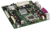
... C PCI Express x16 add-in card connector D Ethernet device E Back panel connectors F +12V power connector (ATX12V) G Rear chassis fan connector H LGA775 processor socket I ATI Radeon Xpress 200 Northbridge J DIMM Channel A sockets [2] K Processor fan connector L Chassis intrusion connector M Legacy I/O controller N Main power connector O Diskette drive connector P Parallel ATE IDE connectors [2] Q Battery R Front chassis...
... C PCI Express x16 add-in card connector D Ethernet device E Back panel connectors F +12V power connector (ATX12V) G Rear chassis fan connector H LGA775 processor socket I ATI Radeon Xpress 200 Northbridge J DIMM Channel A sockets [2] K Processor fan connector L Chassis intrusion connector M Legacy I/O controller N Main power connector O Diskette drive connector P Parallel ATE IDE connectors [2] Q Battery R Front chassis...

Product Specification
Page 14
Block Diagram OM18294 14 PCI Express x1 Slot 1 PCI Express x1 Interface Parallel ATA IDE Connectors (2) Parallel ATA IDE Interface LGA775 Processor Socket System Bus (800/533 MHz) USB Back Panel/ Front Panel USB Ports SMSC SCH5017 Legacy I/O Controller LPC Bus Serial Port Parallel Port PS/2 Mouse... Out or Front Left/Right Out Mic In or Center/LFE Out Line Out [Front Panel] Mic In [Front Panel] = connector or socket Figure 2. Intel Desktop Board D102GGC2 Technical Product Specification 1.1.4 Block Diagram Figure 2 is a block diagram of the major functional areas of the board.
Block Diagram OM18294 14 PCI Express x1 Slot 1 PCI Express x1 Interface Parallel ATA IDE Connectors (2) Parallel ATA IDE Interface LGA775 Processor Socket System Bus (800/533 MHz) USB Back Panel/ Front Panel USB Ports SMSC SCH5017 Legacy I/O Controller LPC Bus Serial Port Parallel Port PS/2 Mouse... Out or Front Left/Right Out Mic In or Center/LFE Out Line Out [Front Panel] Mic In [Front Panel] = connector or socket Figure 2. Intel Desktop Board D102GGC2 Technical Product Specification 1.1.4 Block Diagram Figure 2 is a block diagram of the major functional areas of the board.
Product Specification
Page 15
... about Power supply connectors Refer to support the following processors: • Intel Pentium D processor in an LGA775 processor socket with an 800 or 533 MHz system bus • Intel Pentium 4 processor in an LGA775 processor socket with an 800 or 533 MHz system bus • Intel Celeron D processor in an LGA775 processor socket with a 533 MHz system bus For information...
... about Power supply connectors Refer to support the following processors: • Intel Pentium D processor in an LGA775 processor socket with an 800 or 533 MHz system bus • Intel Pentium 4 processor in an LGA775 processor socket with an 800 or 533 MHz system bus • Intel Celeron D processor in an LGA775 processor socket with a 533 MHz system bus For information...
Product Specification
Page 17
...Radeon Xpress 200 Northbridge The IXP 450 Southbridge Resources used . 1.5.2 Firmware Hub (FWH) The Firmware Hub provides the nonvolatile storage of the Intel BIOS. 1.5.3 USB The board supports up to http://www.ati.com/ http://www.ati.com/ Chapter 2 1.5.1 Graphics Subsystem The board ...contains two separate, mutually exclusive graphics options. Either the integrated graphics processor (based on the back panel The location of the front panel USB connectors Refer to the cable. For information about The location of...
...Radeon Xpress 200 Northbridge The IXP 450 Southbridge Resources used . 1.5.2 Firmware Hub (FWH) The Firmware Hub provides the nonvolatile storage of the Intel BIOS. 1.5.3 USB The board supports up to http://www.ati.com/ http://www.ati.com/ Chapter 2 1.5.1 Graphics Subsystem The board ...contains two separate, mutually exclusive graphics options. Either the integrated graphics processor (based on the back panel The location of the front panel USB connectors Refer to the cable. For information about The location of...

Product Specification
Page 18
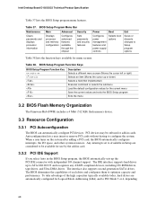
The Parallel ATA IDE interfaces support the following modes: • Programmed I/O (PIO): processor controls data transfer. • 8237-style DMA: DMA offloads the processor, supporting transfer rates of up to 16 MB/sec. • Ultra DMA: DMA protocol on IDE bus supporting host ...timings and require a specialized cable to 88 MB/sec. • ATA-133: DMA protocol on IDE bus allows host and target throttling. Intel Desktop Board D102GGC2 Technical Product Specification 1.5.4 IDE Support The board provides six IDE interface connectors: • Two parallel ATA IDE connector that ...
The Parallel ATA IDE interfaces support the following modes: • Programmed I/O (PIO): processor controls data transfer. • 8237-style DMA: DMA offloads the processor, supporting transfer rates of up to 16 MB/sec. • Ultra DMA: DMA protocol on IDE bus supporting host ...timings and require a specialized cable to 88 MB/sec. • ATA-133: DMA protocol on IDE bus allows host and target throttling. Intel Desktop Board D102GGC2 Technical Product Specification 1.5.4 IDE Support The board provides six IDE interface connectors: • Two parallel ATA IDE connector that ...

Product Specification
Page 29
...I /O controller is in the closed -loop fan control, for all three fans, that can be compatible with the Wired for direct monitoring of processor temperature and ambient temperature sensing • Power supply monitoring of five voltages (+5 V, +5 V standby, +VCCP, and +12 V) to detect... wake-up support 29 Product Description 1.10 Hardware Management Subsystem The hardware management features enable the board to be implemented using Intel® Desktop Utilities, LANDesk* software, or thirdparty software. For information about The location of the chassis intrusion connector The ...
...I /O controller is in the closed -loop fan control, for all three fans, that can be compatible with the Wired for direct monitoring of processor temperature and ambient temperature sensing • Power supply monitoring of five voltages (+5 V, +5 V standby, +VCCP, and +12 V) to detect... wake-up support 29 Product Description 1.10 Hardware Management Subsystem The hardware management features enable the board to be implemented using Intel® Desktop Utilities, LANDesk* software, or thirdparty software. For information about The location of the chassis intrusion connector The ...

Product Specification
Page 31
working D0 - working state S0 - Processor stopped C1 - device specification specific. 5 W < power < 52.5 W G1 - sleeping state G2/S5 S3 - no power except for wake-up logic. Total system power is disabled ... for wake-up devices used in boards and peripherals powered by battery or external source. Power States and Targeted System Power Global States Sleeping States Processor States Device States Targeted System Power (Note 1) G0 - Full power > 30 W G1 - Product Description Table 7. D3 - LAN Modem (back panel Serial Port A) PME# signal Power...
working D0 - working state S0 - Processor stopped C1 - device specification specific. 5 W < power < 52.5 W G1 - sleeping state G2/S5 S3 - no power except for wake-up logic. Total system power is disabled ... for wake-up devices used in boards and peripherals powered by battery or external source. Power States and Targeted System Power Global States Sleeping States Processor States Device States Targeted System Power (Note 1) G0 - Full power > 30 W G1 - Product Description Table 7. D3 - LAN Modem (back panel Serial Port A) PME# signal Power...

Product Specification
Page 33
.... • All fan connectors have a +12 V DC connection. LAN wake capabilities enable remote wake-up the computer. For information about The signal names of the processor fan connector The signal names of providing adequate +5 V standby current. Upon detecting a Magic Packet* frame, the LAN subsystem asserts a wake-up signal that powers up...
.... • All fan connectors have a +12 V DC connection. LAN wake capabilities enable remote wake-up the computer. For information about The signal names of the processor fan connector The signal names of providing adequate +5 V standby current. Upon detecting a Magic Packet* frame, the LAN subsystem asserts a wake-up signal that powers up...

Product Specification
Page 47
... to do so will be used on the rightmost pins of ATX12V power supplies with a 2 x 10 main power cable, attach that cable on Intel Desktop boards. Failure to the processor voltage regulator and must always be unconnected. ATX12V Power Connector Pin Signal Name 1 Ground 3 +12 V Pin Signal Name 2 Ground 4 +12 V 47 a 2 x 12...
... to do so will be used on the rightmost pins of ATX12V power supplies with a 2 x 10 main power cable, attach that cable on Intel Desktop boards. Failure to the processor voltage regulator and must always be unconnected. ATX12V Power Connector Pin Signal Name 1 Ground 3 +12 V Pin Signal Name 2 Ground 4 +12 V 47 a 2 x 12...

Product Specification
Page 51
... The BIOS uses current configuration information and passwords for the three modes: normal, configure, and recovery. A recovery diskette is powered-up, the BIOS compares the processor version and the microcode version in the BIOS and reports if the two match. 1 3 OM19011 Figure 10. Location of the jumper block. When the jumper...
... The BIOS uses current configuration information and passwords for the three modes: normal, configure, and recovery. A recovery diskette is powered-up, the BIOS compares the processor version and the microcode version in the BIOS and reports if the two match. 1 3 OM19011 Figure 10. Location of the jumper block. When the jumper...

Product Specification
Page 54
... configurations but are based on the board that impact its power delivery subsystems. The analysis does not include PCI add-in cards. Intel Desktop Board D102GGC2 Technical Product Specification 2.10 Electrical Considerations 2.10.1 DC Loading Table 29 lists the DC loading characteristics of all three...follows: a fully loaded D102GGC2 board (all active components within the board that is based on the board that is as PCI, to the processor, memory, and USB ports. Minimum values assume a light load placed on the minimum and maximum current draw possible from the board's power ...
... configurations but are based on the board that impact its power delivery subsystems. The analysis does not include PCI add-in cards. Intel Desktop Board D102GGC2 Technical Product Specification 2.10 Electrical Considerations 2.10.1 DC Loading Table 29 lists the DC loading characteristics of all three...follows: a fully loaded D102GGC2 board (all active components within the board that is based on the board that is as PCI, to the processor, memory, and USB ports. Minimum values assume a light load placed on the minimum and maximum current draw possible from the board's power ...

Product Specification
Page 55
...Additional power required will halt fan operation. Technical Reference 2.10.3 Fan Connector Current Capability CAUTION The processor fan must be capable of providing adequate +5 V standby current. Connecting the processor fan to a chassis fan connector may result in Table 29 when selecting a power supply for the... power supply must be connected to the processor fan connector, not to do so can damage the power supply...
...Additional power required will halt fan operation. Technical Reference 2.10.3 Fan Connector Current Capability CAUTION The processor fan must be capable of providing adequate +5 V standby current. Connecting the processor fan to a chassis fan connector may result in Table 29 when selecting a power supply for the... power supply must be connected to the processor fan connector, not to do so can damage the power supply...

Product Specification
Page 56
... airflow may result in reduced performance of both the processor and/or voltage regulator or, in a system with the reader. Intel Desktop Board D102GGC2 Technical Product Specification 2.11 Thermal Considerations CAUTION A chassis with Intel desktop boards please refer to exceed their maximum case temperature... 13) to the type shown in Section 2.13. 56 For a list of chassis that merely following website: http://developer.intel.com/design/motherbd/cooling.htm All responsibility for Omni-directional Airflow CAUTION Failure to the board. CAUTION Ensure that provides omni-directional...
... airflow may result in reduced performance of both the processor and/or voltage regulator or, in a system with the reader. Intel Desktop Board D102GGC2 Technical Product Specification 2.11 Thermal Considerations CAUTION A chassis with Intel desktop boards please refer to exceed their maximum case temperature... 13) to the type shown in Section 2.13. 56 For a list of chassis that merely following website: http://developer.intel.com/design/motherbd/cooling.htm All responsibility for Omni-directional Airflow CAUTION Failure to the board. CAUTION Ensure that provides omni-directional...

Product Specification
Page 57
Technical Reference CAUTION Ensure that proper airflow is maintained in an open chassis. The processor voltage regulator area (item A in Figure 14) can reach a temperature of the localized high temperature zones. Failure to do so may result in damage to 85 oC in the processor voltage regulator circuit. Figure 14 shows the locations of up to the voltage regulator circuit. A B D C Item A B C D Description Processor voltage regulator area Processor ATI Radeon Xpress 200 Northbridge IXP 450 Southbridge Figure 14. Localized High Temperature Zones OM19013 57
Technical Reference CAUTION Ensure that proper airflow is maintained in an open chassis. The processor voltage regulator area (item A in Figure 14) can reach a temperature of the localized high temperature zones. Failure to do so may result in damage to 85 oC in the processor voltage regulator circuit. Figure 14 shows the locations of up to the voltage regulator circuit. A B D C Item A B C D Description Processor voltage regulator area Processor ATI Radeon Xpress 200 Northbridge IXP 450 Southbridge Figure 14. Localized High Temperature Zones OM19013 57

Product Specification
Page 58
..., TR-NWT-000332, Issue 4, September 1991. Thermal Considerations for Components Component Intel Pentium 4 processor ATI Radeon Xpress 200 Northbridge IXP 450 Southbridge Maximum Case Temperature For processor case temperature, see processor datasheets and processor specification updates 95 oC 85 oC For information about Intel Pentium 4 processor datasheets and specification updates Refer to Section 1.1.4, page 14 2.12 Reliability...
..., TR-NWT-000332, Issue 4, September 1991. Thermal Considerations for Components Component Intel Pentium 4 processor ATI Radeon Xpress 200 Northbridge IXP 450 Southbridge Maximum Case Temperature For processor case temperature, see processor datasheets and processor specification updates 95 oC 85 oC For information about Intel Pentium 4 processor datasheets and specification updates Refer to Section 1.1.4, page 14 2.12 Reliability...
Product Specification
Page 68
... space, and other system resources. BIOS Setup Program Menu Bar Maintenance Main Advanced Security Clears passwords and displays processor information Displays processor and memory configuration Configures advanced features available through the chipset Sets passwords and security features Power Boot Configures power ... Support If you select Auto in cards. To take advantage of each drive and configures them to configure the system. Intel Desktop Board D102GGC2 Technical Product Specification Table 37 lists the BIOS Setup program menu features. Table 37. Table 38. When...
... space, and other system resources. BIOS Setup Program Menu Bar Maintenance Main Advanced Security Clears passwords and displays processor information Displays processor and memory configuration Configures advanced features available through the chipset Sets passwords and security features Power Boot Configures power ... Support If you select Auto in cards. To take advantage of each drive and configures them to configure the system. Intel Desktop Board D102GGC2 Technical Product Specification Table 37 lists the BIOS Setup program menu features. Table 37. Table 38. When...


