

Instruction Manual
Page 5
TABLE OF CONTENTS FOREWORD i EXPLICIT DEFINITIONS i FEATURES i IMPORTANT i PRECAUTIONS ii FCC INFORMATION iii SUPPLIED ACCESSORIES iii TABLE OF CONTENTS iv-vi QUICK REFERENCE GUIDE I-XI N Installation I N Your first contact VIII N Repeater operation X N Programming memory channels XI 1 PANEL DESCRIPTION 1-10 N Main unit 1 N Front panel 2 N Function display 4 N Microphone (HM-133 7 N ...
TABLE OF CONTENTS FOREWORD i EXPLICIT DEFINITIONS i FEATURES i IMPORTANT i PRECAUTIONS ii FCC INFORMATION iii SUPPLIED ACCESSORIES iii TABLE OF CONTENTS iv-vi QUICK REFERENCE GUIDE I-XI N Installation I N Your first contact VIII N Repeater operation X N Programming memory channels XI 1 PANEL DESCRIPTION 1-10 N Main unit 1 N Front panel 2 N Function display 4 N Microphone (HM-133 7 N ...
Instruction Manual
Page 8
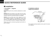
... main unit's top cover, particularly around the internal speaker grill. Please note that the controller may erase the contents of magnetic storage devices. QUICK REFERENCE GUIDE Installation D Precaution -
... main unit's top cover, particularly around the internal speaker grill. Please note that the controller may erase the contents of magnetic storage devices. QUICK REFERENCE GUIDE Installation D Precaution -
Instruction Manual
Page 9
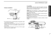
... bodily injury. NEVER place the transceiver or remote controller where normal operation of the transceiver and does not interfere with driving. QUICK REFERENCE QUICK REFERENCE GUIDE • Remote installation Controller Main unit D Location Select a location which can be used for installation. • Optional OPC-440 MICROPHONE CABLE (5.0 m; 16.4 ft) and OPC...
... bodily injury. NEVER place the transceiver or remote controller where normal operation of the transceiver and does not interfere with driving. QUICK REFERENCE QUICK REFERENCE GUIDE • Remote installation Controller Main unit D Location Select a location which can be used for installation. • Optional OPC-440 MICROPHONE CABLE (5.0 m; 16.4 ft) and OPC...
Instruction Manual
Page 10
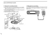
..., nuts and washers through the mounting bracket and tighten. approx. 2-3 mm (1⁄8″) when using self-tapping screws 25° Mounting nut III QUICK REFERENCE GUIDE D Using the mounting bracket q Drill 4 holes where the mounting bracket is available on the main unit front panel.
..., nuts and washers through the mounting bracket and tighten. approx. 2-3 mm (1⁄8″) when using self-tapping screws 25° Mounting nut III QUICK REFERENCE GUIDE D Using the mounting bracket q Drill 4 holes where the mounting bracket is available on the main unit front panel.

Instruction Manual
Page 11
... q Release latch w e Main unit CAUTION: NEVER short the terminals of the arrow until the controller is locked and makes a 'click' sound. QUICK REFERENCE QUICK REFERENCE GUIDE D Controller's attachment/detachment You can be separated from the main unit as a remote controller. IV Connect the controller and the main unit using with the...
... q Release latch w e Main unit CAUTION: NEVER short the terminals of the arrow until the controller is locked and makes a 'click' sound. QUICK REFERENCE QUICK REFERENCE GUIDE D Controller's attachment/detachment You can be separated from the main unit as a remote controller. IV Connect the controller and the main unit using with the...

Instruction Manual
Page 12
... surface using with magnets) CAUTION: NEVER use any other than the supplied screws (FH M2.6 × 8 mm) for attaching the remote controller bracket. QUICK REFERENCE GUIDE D Remote installation The supplied remote controller bracket is used for maximum visibility of the function display.
... surface using with magnets) CAUTION: NEVER use any other than the supplied screws (FH M2.6 × 8 mm) for attaching the remote controller bracket. QUICK REFERENCE GUIDE D Remote installation The supplied remote controller bracket is used for maximum visibility of the function display.

Instruction Manual
Page 13
... DC power supply is grounded. • CONNECTING TO A DC POWER SUPPLY to prevent a short circuit. • CONNECTING TO A DC POWER SOURCE Grommet ID-880H D DC power supply connection Use a 13.8 V DC power supply with at least 15 A capacity. Solder _+ _ black + red See p. 165 ...fuse holders. _ black Fuses 20 A 12 V battery Supplied DC power cable 12 V NOTE: Crimp Use terminals for fuse replacement. QUICK REFERENCE GUIDE QUICK REFERENCE D Battery connection ±R WARNING NEVER remove the fuse holders from the DC power cable. ±NEVER connect the transceiver directly to...
... DC power supply is grounded. • CONNECTING TO A DC POWER SUPPLY to prevent a short circuit. • CONNECTING TO A DC POWER SOURCE Grommet ID-880H D DC power supply connection Use a 13.8 V DC power supply with at least 15 A capacity. Solder _+ _ black + red See p. 165 ...fuse holders. _ black Fuses 20 A 12 V battery Supplied DC power cable 12 V NOTE: Crimp Use terminals for fuse replacement. QUICK REFERENCE GUIDE QUICK REFERENCE D Battery connection ±R WARNING NEVER remove the fuse holders from the DC power cable. ±NEVER connect the transceiver directly to...

Instruction Manual
Page 14
... on and solder it in ) NOTE: There are many publications covering proper antennas and their installation. w Strip the cable as shown at left. QUICK REFERENCE GUIDE D Antenna installation • Antenna location To obtain maximum performance from the transceiver, select a high-quality antenna and mount it . It is not necessary to use...
... on and solder it in ) NOTE: There are many publications covering proper antennas and their installation. w Strip the cable as shown at left. QUICK REFERENCE GUIDE D Antenna installation • Antenna location To obtain maximum performance from the transceiver, select a high-quality antenna and mount it . It is not necessary to use...
Instruction Manual
Page 15
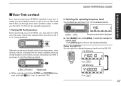
...] Partial reset ± While pushing and holding [S.MW] and [VFO/MHz] keys, push and hold [ ] for 1 sec. Selecting the operating frequency band The ID-880H can select the desired frequency band from the HM-133. • 144 MHz band Push • 400 MHz band Push VIII QUICK REFERENCE QUICK REFERENCE... GUIDE Your first contact Now that you have purchased a brand new transceiver, some settings may want to make your car or shack, you ...
...] Partial reset ± While pushing and holding [S.MW] and [VFO/MHz] keys, push and hold [ ] for 1 sec. Selecting the operating frequency band The ID-880H can select the desired frequency band from the HM-133. • 144 MHz band Push • 400 MHz band Push VIII QUICK REFERENCE QUICK REFERENCE... GUIDE Your first contact Now that you have purchased a brand new transceiver, some settings may want to make your car or shack, you ...
Instruction Manual
Page 16
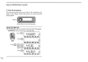
Using the HM-133 You can directly enter the frequency with the HM-133 keypad. [EXAMPLE]: Setting frequency to use. QUICK REFERENCE GUIDE 3. Push Push Push Push IX Page 15 will allow you to dial in the frequency you on how to set the tuning speed. [DIAL] Rotate [DIAL] to tune the frequency. Tune the frequency The tuning dial will instruct you want to 145.3625 MHz.
Using the HM-133 You can directly enter the frequency with the HM-133 keypad. [EXAMPLE]: Setting frequency to use. QUICK REFERENCE GUIDE 3. Push Push Push Push IX Page 15 will allow you to dial in the frequency you on how to set the tuning speed. [DIAL] Rotate [DIAL] to tune the frequency. Tune the frequency The tuning dial will instruct you want to 145.3625 MHz.

Instruction Manual
Page 17
... rotate [DIAL] to select minus duplex or plus duplex selection, push [FUNC] then [DUP- 7(TONE)] to turn the repeater tone ON. QUICK REFERENCE QUICK REFERENCE GUIDE Repeater operation 1.
... rotate [DIAL] to select minus duplex or plus duplex selection, push [FUNC] then [DUP- 7(TONE)] to turn the repeater tone ON. QUICK REFERENCE QUICK REFERENCE GUIDE Repeater operation 1.

Instruction Manual
Page 18
QUICK REFERENCE GUIDE Programming memory channels The ID-880H has a total of 1052 memory channels (including 25 pairs scan edges and 2 call channels) for 1 sec. r Push [FUNC] then push and hold [MW](S.MW) for 1 ...
QUICK REFERENCE GUIDE Programming memory channels The ID-880H has a total of 1052 memory channels (including 25 pairs scan edges and 2 call channels) for 1 sec. r Push [FUNC] then push and hold [MW](S.MW) for 1 ...
Instruction Manual
Page 22
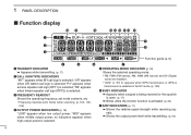
.... • Frequency decimal point blinks while scanning. (p. 102, 105, 106) r OUTPUT POWER INDICATORS (p. 18) "LOW" appears when low output power; 1 PANEL DESCRIPTION Function display !8 !7 !6 !5 !4 !3 !2 !1 !0 q o w i e Function guide (p. 6) r t y q TRANSMIT INDICATOR ± Appears while transmitting. (p. 17) w CALL SIGN TYPE INDICATORS "MY"" appears when MY call sign is selected; "UR" appears when UR station call...
.... • Frequency decimal point blinks while scanning. (p. 102, 105, 106) r OUTPUT POWER INDICATORS (p. 18) "LOW" appears when low output power; 1 PANEL DESCRIPTION Function display !8 !7 !6 !5 !4 !3 !2 !1 !0 q o w i e Function guide (p. 6) r t y q TRANSMIT INDICATOR ± Appears while transmitting. (p. 17) w CALL SIGN TYPE INDICATORS "MY"" appears when MY call sign is selected; "UR" appears when UR station call...

Instruction Manual
Page 24
...select the lower layer. (p. 116) r ENTER KEY [ ](MONI) ± During programming state for call signs, repeater list, etc., push to set condition guide indication, [BAND] key is also used instead of functions. q CLEAR KEY [CLR](DR) ± During programming state for call signs, repeater list, memory name...pgs. 31, 33, 39, 40, 94) ± During programming state for 1 sec to !0). • Set condition guides q wer VFO/MHz M/CALL DR CS LOW MONI Set condition guides appear when the transceiver enters the MENU screen, select memory write state, etc. Push and hold for below the keys...
...select the lower layer. (p. 116) r ENTER KEY [ ](MONI) ± During programming state for call signs, repeater list, etc., push to set condition guide indication, [BAND] key is also used instead of functions. q CLEAR KEY [CLR](DR) ± During programming state for call signs, repeater list, memory name...pgs. 31, 33, 39, 40, 94) ± During programming state for 1 sec to !0). • Set condition guides q wer VFO/MHz M/CALL DR CS LOW MONI Set condition guides appear when the transceiver enters the MENU screen, select memory write state, etc. Push and hold for below the keys...

Instruction Manual
Page 189
..., 121 Frequency offset programming (OFF SET 38 Frequency programming (FREQ 37 Frequency range and offset direction 25 Front panel 2 Full scan 102 Function display 4 Function guide indicator 6 Fuse replacement 165 - EMR communication 67 EMR function (EMR 137 Entering MENU screen and operation 116 Entering MENU screen via the microphone 117 Erasing...
..., 121 Frequency offset programming (OFF SET 38 Frequency programming (FREQ 37 Frequency range and offset direction 25 Front panel 2 Full scan 102 Function display 4 Function guide indicator 6 Fuse replacement 165 - EMR communication 67 EMR function (EMR 137 Entering MENU screen and operation 116 Entering MENU screen via the microphone 117 Erasing...

Instruction Manual
Page 191
... tone frequency (R TONE 121 Reverse DTCS squelch 147 Reverse tone squelch 147 1 2 3 4 5 6 7 8 9 10 11 12 13 14 15 16 17 18 19 173 Quick reference guide I Precautions ii Preparation 11 Priority watch (PRIO 111, 123 Priority watch operation 112 Priority watch types 111 Program scan link function (P-LINK 125 Program skip...
... tone frequency (R TONE 121 Reverse DTCS squelch 147 Reverse tone squelch 147 1 2 3 4 5 6 7 8 9 10 11 12 13 14 15 16 17 18 19 173 Quick reference guide I Precautions ii Preparation 11 Priority watch (PRIO 111, 123 Priority watch operation 112 Priority watch types 111 Program scan link function (P-LINK 125 Program skip...

Instruction Manual
Page 192
..., 123 Scan start/stop via the microphone 107 Scan stop beep (STOP B 133 Scan types 100 Scroll speed (SCROLL 136 Secondary function guides 6 Selecting a call channel 89 Selecting a memory channel 88 Selecting a call record via the microphone 110 Setting tone squelch frequency 147 Simplex... setting (GSV 74, 139 Sentence formatter setting (RMC 74, 139 Sentence formatter setting (VTG 74, 139 Separation cable connection IV Set condition guide guides 6 SET mode - FUNC items 127 SET mode - SOUNDS items 132 Setting a memory channel XI Setting DTCS code 148 Setting duplex X Setting...
..., 123 Scan start/stop via the microphone 107 Scan stop beep (STOP B 133 Scan types 100 Scroll speed (SCROLL 136 Secondary function guides 6 Selecting a call channel 89 Selecting a memory channel 88 Selecting a call record via the microphone 110 Setting tone squelch frequency 147 Simplex... setting (GSV 74, 139 Sentence formatter setting (RMC 74, 139 Sentence formatter setting (VTG 74, 139 Separation cable connection IV Set condition guide guides 6 SET mode - FUNC items 127 SET mode - SOUNDS items 132 Setting a memory channel XI Setting DTCS code 148 Setting duplex X Setting...