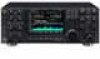
Instruction Manual
Page 9
... D Color setting 14-10 D Bandscope edge frequency setting 14-10 D Data mode with filter width setting 14-10 D Antenna memory setting 14-10 Section 15 SPECIFICATIONS AND OPTIONS I Specifications 15-2 D General 15-2 D Transmitter 15-2 D Receiver 15-3 D Antenna tuner 15-3 I Options 15-4 viii
... D Color setting 14-10 D Bandscope edge frequency setting 14-10 D Data mode with filter width setting 14-10 D Antenna memory setting 14-10 Section 15 SPECIFICATIONS AND OPTIONS I Specifications 15-2 D General 15-2 D Transmitter 15-2 D Receiver 15-3 D Antenna tuner 15-3 I Options 15-4 viii

Instruction Manual
Page 35
... the CW side tone or beep tone decreases from the fixed level when the [AF] control is ON. NAME DESCRIPTION 1 8 V Regulated 8 V output. SPECIFICATIONS Output voltage Output current : 8 V ±0.3 V : Less than 10 mA 2 GND Same as ACC 1 pin 2. 3 SEND Same as ACC 1...13.8 V 7 13.8 V Same as ACC 1 pin 8. 6 TRV Activates [X-VERTER] input/output when "HIGH" voltage is applied. NAME DESCRIPTION 1 RTTY Controls RTTY keying SPECIFICATIONS "High" level "Low" level Output current : More than 2.4 V : Less than 0.6 V : Less than 10 kΩ Connected in parallel with ACC 2 pin 7....
... the CW side tone or beep tone decreases from the fixed level when the [AF] control is ON. NAME DESCRIPTION 1 8 V Regulated 8 V output. SPECIFICATIONS Output voltage Output current : 8 V ±0.3 V : Less than 10 mA 2 GND Same as ACC 1 pin 2. 3 SEND Same as ACC 1...13.8 V 7 13.8 V Same as ACC 1 pin 8. 6 TRV Activates [X-VERTER] input/output when "HIGH" voltage is applied. NAME DESCRIPTION 1 RTTY Controls RTTY keying SPECIFICATIONS "High" level "Low" level Output current : More than 2.4 V : Less than 0.6 V : Less than 10 kΩ Connected in parallel with ACC 2 pin 7....
Instruction Manual
Page 59
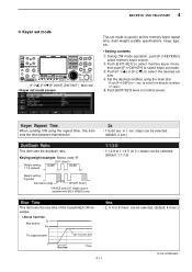
...;DEF] [EXIT/SET] Main dial • Keyer set mode screen This set mode is used to set the memory keyer repeat time, dash weight, paddle specifications, keyer type, etc. • Setting contents q During CW mode operation, push [F-3•KEYER] to normal screen. t Push [EXIT/SET] twice to select memory keyer screen...
...;DEF] [EXIT/SET] Main dial • Keyer set mode screen This set mode is used to set the memory keyer repeat time, dash weight, paddle specifications, keyer type, etc. • Setting contents q During CW mode operation, push [F-3•KEYER] to normal screen. t Push [EXIT/SET] twice to select memory keyer screen...

Instruction Manual
Page 190
SPECIFICATIONS AND OPTIONS Section 15 I Specifications 15-2 D General 15-2 D Transmitter 15-2 D Receiver 15-3 D Antenna tuner 15-3 I Options 15-4 15-1
SPECIFICATIONS AND OPTIONS Section 15 I Specifications 15-2 D General 15-2 D Transmitter 15-2 D Receiver 15-3 D Antenna tuner 15-3 I Options 15-4 15-1
Instruction Manual
Page 191
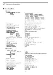
15 SPECIFICATIONS AND OPTIONS I /O], ON, 0-50˚C; 32-122˚F) : 1 Hz : 85-265 V AC (universal input) : 10 VA typical 200 VA typical 210 VA typical 800 VA : ... than 63 dB (HF bands) More than 73 dB (50 MHz band) : More than ±0.05 ppm (approx. 5 min. after from turn the main power, [I Specifications D General • Frequency coverage (unit: MHz) Receiver Transmitter • Operating mode • Number of memory channels • Antenna connector • Operating temperature range • Frequency...
15 SPECIFICATIONS AND OPTIONS I /O], ON, 0-50˚C; 32-122˚F) : 1 Hz : 85-265 V AC (universal input) : 10 VA typical 200 VA typical 210 VA typical 800 VA : ... than 63 dB (HF bands) More than 73 dB (50 MHz band) : More than ±0.05 ppm (approx. 5 min. after from turn the main power, [I Specifications D General • Frequency coverage (unit: MHz) Receiver Transmitter • Operating mode • Number of memory channels • Antenna connector • Operating temperature range • Frequency...

Instruction Manual
Page 192
All stated specifications are typical and subject to 125 Ω unbalanced (50 MHz band; VSWR better than 3:1) 20 to change without notice or obligation. 15-3 They are made ... tuning) : 16.7 to 150 Ω unbalanced (HF bands; This is not a malfunction or defect, but a normal characteristic of the transceiver's condition (Tx or Rx). 15 SPECIFICATIONS AND OPTIONS D Receiver • Receive system : Double conversion superheterodyne system • Intermediate frequencies : 1st 64.455 MHz (MAIN band) 64.555 MHz (SUB band) 2nd...
All stated specifications are typical and subject to 125 Ω unbalanced (50 MHz band; VSWR better than 3:1) 20 to change without notice or obligation. 15-3 They are made ... tuning) : 16.7 to 150 Ω unbalanced (HF bands; This is not a malfunction or defect, but a normal characteristic of the transceiver's condition (Tx or Rx). 15 SPECIFICATIONS AND OPTIONS D Receiver • Receive system : Double conversion superheterodyne system • Intermediate frequencies : 1st 64.455 MHz (MAIN band) 64.555 MHz (SUB band) 2nd...
Instruction Manual
Page 193
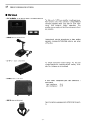
... SPEAKER • HM-36 HAND MICROPHONE For remote transceiver control using a PC. headphone jack; input power : 5 W Hand microphone equipped with an Icom transceiver. Full break-in (QSK) operation. You can connect to 2 transceivers. • Input impedance : 8 Ω • Max. The ...remote control unit are separate. • SM-20 DESKTOP MICROPHONE Unidirectional, electret microphone for base station operation. 15 SPECIFICATIONS AND OPTIONS I Options • IC-PW1/EURO HF/50 MHz ALL BAND 1 kW LINEAR AMPLIFIER Full-duty-cycle 1 kW linear amplifier including an automatic...
... SPEAKER • HM-36 HAND MICROPHONE For remote transceiver control using a PC. headphone jack; input power : 5 W Hand microphone equipped with an Icom transceiver. Full break-in (QSK) operation. You can connect to 2 transceivers. • Input impedance : 8 Ω • Max. The ...remote control unit are separate. • SM-20 DESKTOP MICROPHONE Unidirectional, electret microphone for base station operation. 15 SPECIFICATIONS AND OPTIONS I Options • IC-PW1/EURO HF/50 MHz ALL BAND 1 kW LINEAR AMPLIFIER Full-duty-cycle 1 kW linear amplifier including an automatic...