Instruction Manual
Page 2
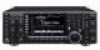
... the LCD may cause harmful interference to provide reasonable protection against harmful interference in a particular installation. FOREWORD Thank you agree with Icom's philosophy of "technology first." This manual contains impor- and the logo are designed to radio communications. FOR CLASS B UNINTENTIONAL ... guarantee that to which can radiate radio frequency energy and, if not installed and used in accordance with the limits for making the IC-7700 your IC-7700. This equipment generates, uses and can be determined by turning the equipment off and on, the user is ...
... the LCD may cause harmful interference to provide reasonable protection against harmful interference in a particular installation. FOREWORD Thank you agree with Icom's philosophy of "technology first." This manual contains impor- and the logo are designed to radio communications. FOR CLASS B UNINTENTIONAL ... guarantee that to which can radiate radio frequency energy and, if not installed and used in accordance with the limits for making the IC-7700 your IC-7700. This equipment generates, uses and can be determined by turning the equipment off and on, the user is ...
Instruction Manual
Page 3
...handle. tings of LCD displays. R CAUTION! R CAUTION! R CAUTION! R CAUTION! DO NOT use chemical agents such as they can damage the transceiver's surfaces. cohol when cleaning the IC-7700, as benzine or al- The LCD display may result in any liquids. This is not a malfunction...;F) or above +50°C (+122°F). AVOID placing the transceiver against continuous high volume operation. This may be hot. BE CAREFUL! Use Icom microphones only (supplied or optional). Turn [I/O] switch (on a slanted surface or vibrated place). This may result in a place without adequate ...
...handle. tings of LCD displays. R CAUTION! R CAUTION! R CAUTION! R CAUTION! DO NOT use chemical agents such as they can damage the transceiver's surfaces. cohol when cleaning the IC-7700, as benzine or al- The LCD display may result in any liquids. This is not a malfunction...;F) or above +50°C (+122°F). AVOID placing the transceiver against continuous high volume operation. This may be hot. BE CAREFUL! Use Icom microphones only (supplied or optional). Turn [I/O] switch (on a slanted surface or vibrated place). This may result in a place without adequate ...
Instruction Manual
Page 4
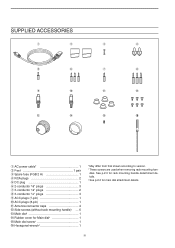
... handle detachment details. ‡ See p.2-2 for Main dial 1 !5 Main dial screw 1 !6 Hexagonal wrench 1 *May differ from that shown according to version. † These screws are used when removing rack mounting handles. iii
... handle detachment details. ‡ See p.2-2 for Main dial 1 !5 Main dial screw 1 !6 Hexagonal wrench 1 *May differ from that shown according to version. † These screws are used when removing rack mounting handles. iii
Instruction Manual
Page 5
... 2-6 D Front panel 2-6 D Rear panel-1 2-6 D Rear panel-2 2-7 ■ Linear amplifier connections 2-8 D Connecting the IC-PW1/EURO 2-8 D Connecting a non-Icom linear amplifier 2-8 ■ Transverter jack information 2-9 ■ FSK and AFSK (SSTV) connections 2-9 ■ Microphone connector information ... mode 3-3 ■ VFO selection 3-3 D Selecting VFO-A/VFO-B 3-3 D VFO equalization 3-3 ■ Selecting an operating band 3-4 D Using the band stacking registers 3-4 ■ Frequency setting 3-5 D Tuning with the main dial 3-5 D Direct frequency entry with the keypad 3-5...
... 2-6 D Front panel 2-6 D Rear panel-1 2-6 D Rear panel-2 2-7 ■ Linear amplifier connections 2-8 D Connecting the IC-PW1/EURO 2-8 D Connecting a non-Icom linear amplifier 2-8 ■ Transverter jack information 2-9 ■ FSK and AFSK (SSTV) connections 2-9 ■ Microphone connector information ... mode 3-3 ■ VFO selection 3-3 D Selecting VFO-A/VFO-B 3-3 D VFO equalization 3-3 ■ Selecting an operating band 3-4 D Using the band stacking registers 3-4 ■ Frequency setting 3-5 D Tuning with the main dial 3-5 D Direct frequency entry with the keypad 3-5...
Instruction Manual
Page 7
... reduction 5-17 ■ Dial lock function 5-17 ■ Notch function 5-18 ■ Digital selector 5-18 ■ Autotune function 5-19 FUNCTIONS FOR TRANSMIT ■ VOX function 6-2 D Using the VOX function 6-2 D Adjusting the VOX function 6-2 D VOX set mode 6-2 ■ Break-in function 6-3 D Semi break-in operation 6-3 D Full break-in operation 6-3 ■ ∂TX...
... reduction 5-17 ■ Dial lock function 5-17 ■ Notch function 5-18 ■ Digital selector 5-18 ■ Autotune function 5-19 FUNCTIONS FOR TRANSMIT ■ VOX function 6-2 D Using the VOX function 6-2 D Adjusting the VOX function 6-2 D VOX set mode 6-2 ■ Break-in function 6-3 D Semi break-in operation 6-3 D Full break-in operation 6-3 ■ ∂TX...
Instruction Manual
Page 8
...10 D Saving the TX memory 7-10 MEMORY OPERATION ■ Memory channels 8-2 ■ Memory channel selection 8-2 D Using the ∫ / √ keys 8-2 D Using the keypad 8-2 ■ Memory channel programming 8-3 D Programming in VFO mode 8-3 D Programming in memory mode 8-3... Frequency transfers 8-4 D Transferring in VFO mode 8-4 D Transferring in memory mode 8-4 ■ Memory list screen 8-5 D Selecting a memory channel using the memory list screen ...... 8-5 D Confirming programmed memory channels 8-5 ■ Memory names 8-6 D Editing (programming) memory names 8-6 ■ ...
...10 D Saving the TX memory 7-10 MEMORY OPERATION ■ Memory channels 8-2 ■ Memory channel selection 8-2 D Using the ∫ / √ keys 8-2 D Using the keypad 8-2 ■ Memory channel programming 8-3 D Programming in VFO mode 8-3 D Programming in memory mode 8-3... Frequency transfers 8-4 D Transferring in VFO mode 8-4 D Transferring in memory mode 8-4 ■ Memory list screen 8-5 D Selecting a memory channel using the memory list screen ...... 8-5 D Confirming programmed memory channels 8-5 ■ Memory names 8-6 D Editing (programming) memory names 8-6 ■ ...
Instruction Manual
Page 12
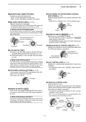
... internal power supply is located on p. 1-12. • Keyer polarity (dot and dash) can select internal electronic keyer, bug-key or straight key operation in use. ➥ Enters timer set mode. (p. 4-12) • A straight key jack is switched ON.
... internal power supply is located on p. 1-12. • Keyer polarity (dot and dash) can select internal electronic keyer, bug-key or straight key operation in use. ➥ Enters timer set mode. (p. 4-12) • A straight key jack is switched ON.
Instruction Manual
Page 13
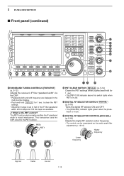
Recommended level for an Icom microphone Increases Decreases Decreases Increases o VOX SWITCH VOX ➥ Push ... • The [MONITOR] indicator above this switch lights green while the function is recommended for the most effective use [AGC] control, push AGC VR ([AGC VR] indicator lights). The VOX function (voice operated transmission) activates ...speed keying !5 AGC CONTROL [AGC] (p. 5-11) Adjusts the continuously-variable AGC circuit time constant. • To use of MONITOR switch setting in SSB, AM and FM modes can monitor the receive signal between CW dots and dashes. ...
Recommended level for an Icom microphone Increases Decreases Decreases Increases o VOX SWITCH VOX ➥ Push ... • The [MONITOR] indicator above this switch lights green while the function is recommended for the most effective use [AGC] control, push AGC VR ([AGC VR] indicator lights). The VOX function (voice operated transmission) activates ...speed keying !5 AGC CONTROL [AGC] (p. 5-11) Adjusts the continuously-variable AGC circuit time constant. • To use of MONITOR switch setting in SSB, AM and FM modes can monitor the receive signal between CW dots and dashes. ...
Instruction Manual
Page 14
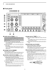
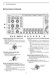
...AF] (inner control; Set for RTTY and PSK31 operations. • USB keyboards* are supported. *: USB-Memory or USB keyboard is not supplied by Icom. @1 NOISE REDUCTION SWITCH NR (p. 5-17) Push to switch DSP noise reduction ON and OFF. • The [NR] indicator above this switch ...• Unmount operation should be performed before removing the USB-Memory* (p.12-25). ➥ Connects a PC keyboard for maximum readability. • To use this control, push NB . 1 PANEL DESCRIPTION ■ Front panel (continued) !7 !8 POWER HF/50MHz TRANSCEIVER i7700 TRANSMIT TUNER VOX BK-IN MONITOR ...
...AF] (inner control; Set for RTTY and PSK31 operations. • USB keyboards* are supported. *: USB-Memory or USB keyboard is not supplied by Icom. @1 NOISE REDUCTION SWITCH NR (p. 5-17) Push to switch DSP noise reduction ON and OFF. • The [NR] indicator above this switch ...• Unmount operation should be performed before removing the USB-Memory* (p.12-25). ➥ Connects a PC keyboard for maximum readability. • To use this control, push NB . 1 PANEL DESCRIPTION ■ Front panel (continued) !7 !8 POWER HF/50MHz TRANSCEIVER i7700 TRANSMIT TUNER VOX BK-IN MONITOR ...
Instruction Manual
Page 15
... receiver to prevent unwanted VOX activation. The noise blanker reduces pulse-type noise such as that generated by automobile ignition systems. This function cannot be used in all modes (other than SSB mode with interference, the automatic tuning function may hear noise. p. 3-9) Adjusts the RF gain level. Push Low sensitivity High...
... receiver to prevent unwanted VOX activation. The noise blanker reduces pulse-type noise such as that generated by automobile ignition systems. This function cannot be used in all modes (other than SSB mode with interference, the automatic tuning function may hear noise. p. 3-9) Adjusts the RF gain level. Push Low sensitivity High...
Instruction Manual
Page 16
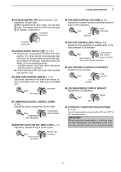
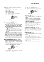
...- When a transverter is in the receiver front end to improve S/N ratio and sensitivity. 1 PANEL DESCRIPTION ■ Front panel (continued) #3 #4 #5 #6 #7 #8 #9 $0 $1 $2 NSCEIVER 7700 MONITOR D DELAY NB NB RF DRIVE TX RX SPLIT LOCK 1.8 1 10 4 21 7 GENE 3.5 2 14 5 24 8 50 0 MP-W MW 7 3 18 6 28 9 F-INP ENT...FUNCTION SWITCHES Push to select the functions indicated in the LCD display to [ANT4] is used for receive only. AMP2" activates 16 dB high-gain pre- The preamp amplifies signals in use, this [ANT] does not function and 'TRV' appears. AMP1" activates 10 dB ...
...- When a transverter is in the receiver front end to improve S/N ratio and sensitivity. 1 PANEL DESCRIPTION ■ Front panel (continued) #3 #4 #5 #6 #7 #8 #9 $0 $1 $2 NSCEIVER 7700 MONITOR D DELAY NB NB RF DRIVE TX RX SPLIT LOCK 1.8 1 10 4 21 7 GENE 3.5 2 14 5 24 8 50 0 MP-W MW 7 3 18 6 28 9 F-INP ENT...FUNCTION SWITCHES Push to select the functions indicated in the LCD display to [ANT4] is used for receive only. AMP2" activates 16 dB high-gain pre- The preamp amplifies signals in use, this [ANT] does not function and 'TRV' appears. AMP1" activates 10 dB ...
Instruction Manual
Page 17
...FM mode. (pgs. 4-33, 4-34) MF7 (MULTI-FUNCTION 7 SWITCH) VSC ➥ Switches the voice squelch control OFF function ON and OFF; useful for 1 sec. ✔ What is the speech compressor? Pushing F-INPENT or ∫ / √ is the AGC? The AGC controls receiver gain ...8226; selects the general coverage band. ➥ Pushing the same key 2 or 3 times calls up other stacked frequencies in the band. (p. 3-4) • Icom's triple band stacking register memorizes 3 frequencies in each band. ➥ After pushing F-INPENT , enters a frequency or memory channel. Select "FAST" for tuning and...
...FM mode. (pgs. 4-33, 4-34) MF7 (MULTI-FUNCTION 7 SWITCH) VSC ➥ Switches the voice squelch control OFF function ON and OFF; useful for 1 sec. ✔ What is the speech compressor? Pushing F-INPENT or ∫ / √ is the AGC? The AGC controls receiver gain ...8226; selects the general coverage band. ➥ Pushing the same key 2 or 3 times calls up other stacked frequencies in the band. (p. 3-4) • Icom's triple band stacking register memorizes 3 frequencies in each band. ➥ After pushing F-INPENT , enters a frequency or memory channel. Select "FAST" for tuning and...
Instruction Manual
Page 19
...Programs the displayed readout frequency and operating mode into a memo pad. • The 5 most recent. • The memo pad capacity can be turned OFF using set mode. (p. 12-12) ➥ Turns the split function ON and shifts the unselected VFO frequency after inputting an offset. 1-9 to stop recording. &#... operation (p. 4-14) ➥ Push to turn the twin peak filter ON and OFF. • " TPF " appears when twin peak filter is in use. %3 MINI SPECTRUM SCOPE SWITCH M.SCOPE (p. 5-4) ➥ Turns the mini spectrum scope screen ON and OFF when pushed. • The mini spectrum scope ...
...Programs the displayed readout frequency and operating mode into a memo pad. • The 5 most recent. • The memo pad capacity can be turned OFF using set mode. (p. 12-12) ➥ Turns the split function ON and shifts the unselected VFO frequency after inputting an offset. 1-9 to stop recording. &#... operation (p. 4-14) ➥ Push to turn the twin peak filter ON and OFF. • " TPF " appears when twin peak filter is in use. %3 MINI SPECTRUM SCOPE SWITCH M.SCOPE (p. 5-4) ➥ Turns the mini spectrum scope screen ON and OFF when pushed. • The mini spectrum scope ...
Instruction Manual
Page 20
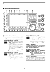
...-CLR (p. 5-12) Clears the PBT settings when pushed and held for 1 sec. • The [PBT-CLR] indicator above this switch lights when PBT is in use . ^4 DIGITAL RF SELECTOR CONTROL [DIGI-SEL] (p. 5-18) Adjusts the digital RF selector center frequency. • The control can be reassigned as the audio peak... function electronically modifies the IF passband width to half of the IF filter passband width. 25 Hz steps and 100 Hz steps are displayed in use . ^3 DIGITAL RF SELECTOR SWITCH DIGI-SEL (p. 5-18) Turns the digital RF selector ON and OFF. • The [DIGI-SEL] indicator lights green when ...
...-CLR (p. 5-12) Clears the PBT settings when pushed and held for 1 sec. • The [PBT-CLR] indicator above this switch lights when PBT is in use . ^4 DIGITAL RF SELECTOR CONTROL [DIGI-SEL] (p. 5-18) Adjusts the digital RF selector center frequency. • The control can be reassigned as the audio peak... function electronically modifies the IF passband width to half of the IF filter passband width. 25 Hz steps and 100 Hz steps are displayed in use . ^3 DIGITAL RF SELECTOR SWITCH DIGI-SEL (p. 5-18) Turns the digital RF selector ON and OFF. • The [DIGI-SEL] indicator lights green when ...
Instruction Manual
Page 21
... the RIT function? Low frequency High frequency ^9 RIT SWITCH RIT (p. 5-10) ➥ Turns the RIT function ON and OFF when pushed. • Use [RIT/∂TX] control to vary the RIT frequency. ➥ Adds the RIT shift frequency to the operating frequency when pushed and held for simple... split frequency operation in use . • " AN " appears when auto notch is a narrow filter that eliminates unwanted CW or AM carrier tones while preserving the desired voice ...
... the RIT function? Low frequency High frequency ^9 RIT SWITCH RIT (p. 5-10) ➥ Turns the RIT function ON and OFF when pushed. • Use [RIT/∂TX] control to vary the RIT frequency. ➥ Adds the RIT shift frequency to the operating frequency when pushed and held for simple... split frequency operation in use . • " AN " appears when auto notch is a narrow filter that eliminates unwanted CW or AM carrier tones while preserving the desired voice ...
Instruction Manual
Page 22
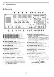
... y CIRCUIT BREAKER Cuts off the AC input when over-current occurs. Can be used to remotely control the IC-7700 without the optional CT-17, or for transceive operation with another Icom CI-V transceiver or receiver. !0 RS-232C TERMINAL [RS-232C] (p. 2-6) Connects ...an RS-232C cable, D-sub 9-pin to connect the IC-7700 to a PC. The [RS-232C] interface is necessary. 1 PANEL DESCRIPTION ■ Rear panel q w e r t y u i o !0 ANT 1 ANT 2...
... y CIRCUIT BREAKER Cuts off the AC input when over-current occurs. Can be used to remotely control the IC-7700 without the optional CT-17, or for transceive operation with another Icom CI-V transceiver or receiver. !0 RS-232C TERMINAL [RS-232C] (p. 2-6) Connects ...an RS-232C cable, D-sub 9-pin to connect the IC-7700 to a PC. The [RS-232C] interface is necessary. 1 PANEL DESCRIPTION ■ Rear panel q w e r t y u i o !0 ANT 1 ANT 2...
Instruction Manual
Page 23
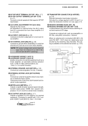
... current must be lower than 16 V DC/0.5 A (or 250 V AC, 200 mA with 13.8 V outputs of external equipment such as preamplifier or RF filter, using BNC connectors, if desired. IN] @8 RECEIVE ANTENNA OUT [RX ANT- Connects an external unit, such as a linear amplifier, an automatic antenna selector/ tuner, a ... circuit and receiver's RF stage. OUT] must be deactivated and shorted by voltage applied to control an external unit, such as a non-Icom linear amplifier. IN] (p. 2-7) !6 S/P DIF OUTPUT TERMINAL [S/P DIF- No adjustment is required when the ALC output level of a connected non...
... current must be lower than 16 V DC/0.5 A (or 250 V AC, 200 mA with 13.8 V outputs of external equipment such as preamplifier or RF filter, using BNC connectors, if desired. IN] @8 RECEIVE ANTENNA OUT [RX ANT- Connects an external unit, such as a linear amplifier, an automatic antenna selector/ tuner, a ... circuit and receiver's RF stage. OUT] must be deactivated and shorted by voltage applied to control an external unit, such as a non-Icom linear amplifier. IN] (p. 2-7) !6 S/P DIF OUTPUT TERMINAL [S/P DIF- No adjustment is required when the ALC output level of a connected non...
Instruction Manual
Page 24
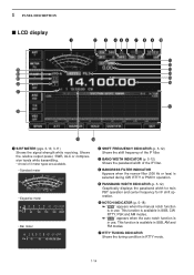
... INDICATOR (p. 5-18) ➥ " MN " appears when the manual notch function is in SSB, AM and FM modes. u RTTY TUNING INDICATOR Shows the tuning condition in use . 1 PANEL DESCRIPTION ■ LCD display q @5 @4 @3 @2 @1 @0 w e r t y u i o !0 !1 !2 !3 !4 !5 !6 !7 !9 !8 q S/RF METER (pgs. 3-10, 3-11) Shows the signal strength while ...center frequency for IF shift operation. r BANDPASS FILTER INDICATOR Appears when the narrow filter (500 Hz or less) is available in use . e BAND WIDTH INDICATOR (p. 5-12) Shows the passband width of the IF filter. This function is available in SSB, ...
... INDICATOR (p. 5-18) ➥ " MN " appears when the manual notch function is in SSB, AM and FM modes. u RTTY TUNING INDICATOR Shows the tuning condition in use . 1 PANEL DESCRIPTION ■ LCD display q @5 @4 @3 @2 @1 @0 w e r t y u i o !0 !1 !2 !3 !4 !5 !6 !7 !9 !8 q S/RF METER (pgs. 3-10, 3-11) Shows the signal strength while ...center frequency for IF shift operation. r BANDPASS FILTER INDICATOR Appears when the narrow filter (500 Hz or less) is available in use . e BAND WIDTH INDICATOR (p. 5-12) Shows the passband width of the IF filter. This function is available in SSB, ...
Instruction Manual
Page 25
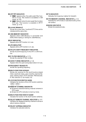
... and blinks while reading or writing the USB-Memory. !1 RIT INDICATOR Appears when RIT function is in use. !2 ∂TX INDICATOR Appears when ∂TX function is in use. !3 RIT/∂TX SHIFT FREQUENCY INDICATOR Shows the shift frequency for the RIT or ∂TX function.... 1-15 F-7 ). !9 MEMORY CHANNEL READOUTS ➥ Shows the selected memory channel contents in VFO mode. ➥ Shows the VFO contents in use. !6 FREQUENCY READOUTS Shows the operating frequency. !7 MULTI-FUNCTION SCREEN Shows the screens for the multi-function digital meter, spectrum scope, voice recorder, memory...
... and blinks while reading or writing the USB-Memory. !1 RIT INDICATOR Appears when RIT function is in use. !2 ∂TX INDICATOR Appears when ∂TX function is in use. !3 RIT/∂TX SHIFT FREQUENCY INDICATOR Shows the shift frequency for the RIT or ∂TX function.... 1-15 F-7 ). !9 MEMORY CHANNEL READOUTS ➥ Shows the selected memory channel contents in VFO mode. ➥ Shows the VFO contents in use. !6 FREQUENCY READOUTS Shows the operating frequency. !7 MULTI-FUNCTION SCREEN Shows the screens for the multi-function digital meter, spectrum scope, voice recorder, memory...
Instruction Manual
Page 26
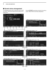
... (p. 8-5) • Voice recorder screen (p. 7-3) F-4 • Scan screen (VFO mode; See p. 12-3 for set mode arrangement. • PSK31 decoder screen (PSK mode; Choose the desired screen using the following screens can be selected from the start up screen. 1 PANEL DESCRIPTION ■ Screen menu arrangement The following chart.
... (p. 8-5) • Voice recorder screen (p. 7-3) F-4 • Scan screen (VFO mode; See p. 12-3 for set mode arrangement. • PSK31 decoder screen (PSK mode; Choose the desired screen using the following screens can be selected from the start up screen. 1 PANEL DESCRIPTION ■ Screen menu arrangement The following chart.

