Instruction Manual
Page 1
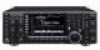
HF/50 MHz TRANSCEIVER i7700 Instruction Manual A-6612H-1EX-q Printed in Japan © 2008 Icom Inc.
HF/50 MHz TRANSCEIVER i7700 Instruction Manual A-6612H-1EX-q Printed in Japan © 2008 Icom Inc.
Instruction Manual
Page 2
... harmful interference in a residential installation. Equipment damage may occur. These limits are registered trademarks of Icom Incorporated (Japan) in a particular installation. However, there is connected. • Consult the dealer...IC-7700. We hope you for a Class B digital device, pursuant to which can radiate radio frequency energy and, if not installed and used in Baudot RTTY and PSK31 modulator/demodulator and direct PC keyboard connection capability for help. center frequency and fixed frequency modes, plus mini-scope displays IMPORTANT READ THIS INSTRUCTION MANUAL...
... harmful interference in a residential installation. Equipment damage may occur. These limits are registered trademarks of Icom Incorporated (Japan) in a particular installation. However, there is connected. • Consult the dealer...IC-7700. We hope you for a Class B digital device, pursuant to which can radiate radio frequency energy and, if not installed and used in Baudot RTTY and PSK31 modulator/demodulator and direct PC keyboard connection capability for help. center frequency and fixed frequency modes, plus mini-scope displays IMPORTANT READ THIS INSTRUCTION MANUAL...
Instruction Manual
Page 12
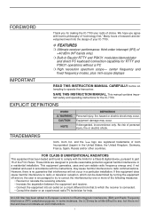
... SWITCH POWER (p. 3-2) Turn the internal power supply ON in keyer set mode when pushed and held for 1 sec. • The [TUNER] indicator blinks red during manual tuning. • When the tuner cannot tune the antenna, the tuning circuit is turned OFF (bypassed). ➥ Tunes the antenna tuner...
... SWITCH POWER (p. 3-2) Turn the internal power supply ON in keyer set mode when pushed and held for 1 sec. • The [TUNER] indicator blinks red during manual tuning. • When the tuner cannot tune the antenna, the tuning circuit is turned OFF (bypassed). ➥ Tunes the antenna tuner...
Instruction Manual
Page 21
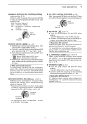
... [CW PITCH] (p. 4-5) Shifts the received CW audio pitch and the CW side tone pitch without shifting the receive frequency. 1 PANEL DESCRIPTION ^5 MANUAL NOTCH FILTER CONTROL [NOTCH] (outer control; The notch function is useful for fine tuning stations calling you off-frequency or when you prefer to listen...Hz Higher frequency Lower frequency ^6 NOTCH SWITCH NOTCH (p. 5-18) ➥ Switches the notch function between auto, manual and OFF in SSB and AM modes. ➥ Turns the manual notch function ON and OFF when pushed in CW, RTTY and PSK31 mode. ➥ Turns the auto notch ...
... [CW PITCH] (p. 4-5) Shifts the received CW audio pitch and the CW side tone pitch without shifting the receive frequency. 1 PANEL DESCRIPTION ^5 MANUAL NOTCH FILTER CONTROL [NOTCH] (outer control; The notch function is useful for fine tuning stations calling you off-frequency or when you prefer to listen...Hz Higher frequency Lower frequency ^6 NOTCH SWITCH NOTCH (p. 5-18) ➥ Switches the notch function between auto, manual and OFF in SSB and AM modes. ➥ Turns the manual notch function ON and OFF when pushed in CW, RTTY and PSK31 mode. ➥ Turns the auto notch ...
Instruction Manual
Page 24
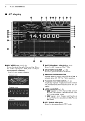
... (p. 5-12) Graphically displays the passband width for twin PBT operation and center frequency for IF shift operation. y NOTCH INDICATOR (p. 5-18) ➥ " MN " appears when the manual notch function is available in RTTY mode. 1-14
... (p. 5-12) Graphically displays the passband width for twin PBT operation and center frequency for IF shift operation. y NOTCH INDICATOR (p. 5-18) ➥ " MN " appears when the manual notch function is available in RTTY mode. 1-14
Instruction Manual
Page 28
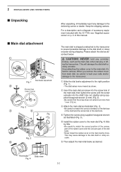
.... This will damage the dial shaft or rotary encoder. w Insert the main dial set-screw into the screw hole of accessory equipment included with the IC-7700, see 'Supplied accessories' on the main dial by little. • Be careful to the delivering carrier or dealer. 2 INSTALLATION AND CONNECTIONS ■ Unpacking ... described below. This may cause damage to match the correct orientation of the flat face of the shaft and the screw hole of this manual. R CAUTION!: NEVER hold any damage to match the correct position of the convex part of the rubber cover and the concave part of...
.... This will damage the dial shaft or rotary encoder. w Insert the main dial set-screw into the screw hole of accessory equipment included with the IC-7700, see 'Supplied accessories' on the main dial by little. • Be careful to the delivering carrier or dealer. 2 INSTALLATION AND CONNECTIONS ■ Unpacking ... described below. This may cause damage to match the correct orientation of the flat face of the shaft and the screw hole of this manual. R CAUTION!: NEVER hold any damage to match the correct position of the convex part of the rubber cover and the concave part of...
Instruction Manual
Page 34
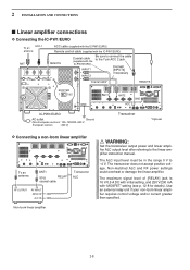
... 0 V to the linear amplifier instruction manual. Non-matched ALC and RF power settings could overheat or damage the linear amplifier. Connect [INPUT2] if necessary Coaxial cable* REMOTE EXCITER 1 1&2 GND ANT1 ANT2 GND ACC 2 IC-PW1/EURO AC outlet Ground (Non-European... versions: 100-120/220-240 V European version : 230 V) Transceiver *Optional D Connecting a non-Icom linear amplifier To an antenna ANT1 50 Ω RELAY coaxial cable Transceiver...
... 0 V to the linear amplifier instruction manual. Non-matched ALC and RF power settings could overheat or damage the linear amplifier. Connect [INPUT2] if necessary Coaxial cable* REMOTE EXCITER 1 1&2 GND ANT1 ANT2 GND ACC 2 IC-PW1/EURO AC outlet Ground (Non-European... versions: 100-120/220-240 V European version : 230 V) Transceiver *Optional D Connecting a non-Icom linear amplifier To an antenna ANT1 50 Ω RELAY coaxial cable Transceiver...
Instruction Manual
Page 35
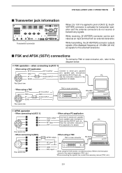
D FSK operation- See the instruction manual of the PC 183 67 SEND PTT application for details. • When using a TNC AFSK output TNC or...port, speaker jack, microphone jack and line IN/OUT jack, etc. PC AF input See the instruction manual of PTT the application for details. Refer to the instruction manual of the displayed frequency at -20 dBm (22 mV) as an input terminal from an external transverter....[X-VERTER] connector outputs signals of the external equipment (TNC, etc.). †When connecting the squelch line, consult the necessary manual (TNC, etc.). 2-9
D FSK operation- See the instruction manual of the PC 183 67 SEND PTT application for details. • When using a TNC AFSK output TNC or...port, speaker jack, microphone jack and line IN/OUT jack, etc. PC AF input See the instruction manual of PTT the application for details. Refer to the instruction manual of the displayed frequency at -20 dBm (22 mV) as an input terminal from an external transverter....[X-VERTER] connector outputs signals of the external equipment (TNC, etc.). †When connecting the squelch line, consult the necessary manual (TNC, etc.). 2-9
Instruction Manual
Page 54
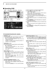
...] controls (inner/outer). • PBT indicator (above PBT-CLR switch) lights when PBT is in 6 dB steps. • Push and hold PBT-CLR for manual notch operation. • Notch indicator (above 10 MHz USB is ON, respectively. • Attenuator (p. 5-9) ➥ Push [ATT] (MF4) several times to ... 5-9) ➥ Push [P.AMP] (MF3) several times to select AGC FAST, AGC MID or AGC SLOW. ➥ Push AGC VR to turn the AGC time constant manual setting ON and OFF. • Rotate [AGC] control to adjust the time constant. • VSC (voice squelch control) (p. 9-3) ➥ Push [VSC] (MF7...
...] controls (inner/outer). • PBT indicator (above PBT-CLR switch) lights when PBT is in 6 dB steps. • Push and hold PBT-CLR for manual notch operation. • Notch indicator (above 10 MHz USB is ON, respectively. • Attenuator (p. 5-9) ➥ Push [ATT] (MF4) several times to ... 5-9) ➥ Push [P.AMP] (MF3) several times to select AGC FAST, AGC MID or AGC SLOW. ➥ Push AGC VR to turn the AGC time constant manual setting ON and OFF. • Rotate [AGC] control to adjust the time constant. • VSC (voice squelch control) (p. 9-3) ➥ Push [VSC] (MF7...
Instruction Manual
Page 56
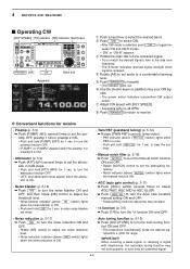
...(p. 5-9) ➥ Push [ATT] (MF4) several times to select AGC FAST, AGC MID or AGC SLOW. ➥ Push AGC VR to turn the AGC time constant manual setting ON and OFF. • Rotate [AGC] control to adjust the time constant. • 1⁄4 function (p. 3-6) ➥ Push [1/4] to turn the 1⁄.... • Twin PBT (passband tuning) (p. 5-12) ➥ Rotate [TWIN PBT] controls (inner/outer). • PBT indicator (above NOTCH switch) lights when the manual notch is in 6 dB steps. • Push and hold NB for 1 sec. tween CW and CW-R modes. • "CW" or "CW-R" appears. amp OFF...
...(p. 5-9) ➥ Push [ATT] (MF4) several times to select AGC FAST, AGC MID or AGC SLOW. ➥ Push AGC VR to turn the AGC time constant manual setting ON and OFF. • Rotate [AGC] control to adjust the time constant. • 1⁄4 function (p. 3-6) ➥ Push [1/4] to turn the 1⁄.... • Twin PBT (passband tuning) (p. 5-12) ➥ Rotate [TWIN PBT] controls (inner/outer). • PBT indicator (above NOTCH switch) lights when the manual notch is in 6 dB steps. • Push and hold NB for 1 sec. tween CW and CW-R modes. • "CW" or "CW-R" appears. amp OFF...
Instruction Manual
Page 65
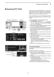
... when signal is built-in the TX buffer screen, will be changed when transmitted. • Press one of displayed text, in to the IC-7700. tents. q Perform the steps q to select RTTY. • After RTTY mode is selected, push and hold RTTY/PSK for a symmetrical.... When connecting a PC keyboard (p. 2-6), RTTY operation can be performed without an external RTTY terminal, TNC or PC. to display the decode screen. • The IC-7700 has a built-in the TX buffer screen. e Push [DECODE] F-3 to toggle between RTTY and RTTY-R modes. • "RTTY" or "RTTY-R" appears. ...
... when signal is built-in the TX buffer screen, will be changed when transmitted. • Press one of displayed text, in to the IC-7700. tents. q Perform the steps q to select RTTY. • After RTTY mode is selected, push and hold RTTY/PSK for a symmetrical.... When connecting a PC keyboard (p. 2-6), RTTY operation can be performed without an external RTTY terminal, TNC or PC. to display the decode screen. • The IC-7700 has a built-in the TX buffer screen. e Push [DECODE] F-3 to toggle between RTTY and RTTY-R modes. • "RTTY" or "RTTY-R" appears. ...
Instruction Manual
Page 66
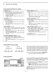
..." or "P.AMP2" appears when the preamp 1 or preamp 2 is ON. • Push and hold RTTY/PSK for 1 sec. to turn the AGC time constant manual setting ON and OFF. • Rotate [AGC] control to adjust the time constant. • 1⁄4 function (p. 3-6) ➥ Push [1/4] to set the attenuating...reduction ON and OFF. • Rotate [NR] control to adjust the noise reduction level. • Noise reduction indicator (above NOTCH switch) lights when the manual notch is ON. • AGC (auto gain control) (p. 5-11) ➥ Push [AGC] switch several times to select RTTY and RTTY-R mode. ...
..." or "P.AMP2" appears when the preamp 1 or preamp 2 is ON. • Push and hold RTTY/PSK for 1 sec. to turn the AGC time constant manual setting ON and OFF. • Rotate [AGC] control to adjust the time constant. • 1⁄4 function (p. 3-6) ➥ Push [1/4] to set the attenuating...reduction ON and OFF. • Rotate [NR] control to adjust the noise reduction level. • Noise reduction indicator (above NOTCH switch) lights when the manual notch is ON. • AGC (auto gain control) (p. 5-11) ➥ Push [AGC] switch several times to select RTTY and RTTY-R mode. ...
Instruction Manual
Page 73
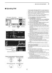
...you want to transmit. • The message is built-in PSK31 decoder. q Perform the steps q to display the decode screen. • The IC-7700 has a built-in to enter the message that comes with the main dial. • The signal is properly tuned when the radiated lines in the... PSK. • After PSK mode is activated. • The water-fall display is selected, push and hold RTTY/PSK for 1 sec. consult the manual that you can also use your PC. When connecting a PC keyboard (p. 2-6), PSK31 operation can be performed without PSK software installed on your PSK software;...
...you want to transmit. • The message is built-in PSK31 decoder. q Perform the steps q to display the decode screen. • The IC-7700 has a built-in to enter the message that comes with the main dial. • The signal is properly tuned when the radiated lines in the... PSK. • After PSK mode is activated. • The water-fall display is selected, push and hold RTTY/PSK for 1 sec. consult the manual that you can also use your PC. When connecting a PC keyboard (p. 2-6), PSK31 operation can be performed without PSK software installed on your PSK software;...
Instruction Manual
Page 74
...indicator (above PBT-CLR switch) lights when PBT is OFF (no "Z" indication), push and hold [P.AMP] (MF3) for 1 sec. to turn the manual notch function ON and OFF. • Rotate [NOTCH] control to set the attenuating fre- However, more accurate tuning is the most commonly used mode. ...mode has error correction capability to provide better decoding than BPSK mode in marginal condition. quency. • Notch indicator (above NOTCH switch) lights when the manual notch is ON. • Fine tuning (p. 3-7) ➥ During PSK, make sure that the kHz tuning step function is in 6 dB steps....
...indicator (above PBT-CLR switch) lights when PBT is OFF (no "Z" indication), push and hold [P.AMP] (MF3) for 1 sec. to turn the manual notch function ON and OFF. • Rotate [NOTCH] control to set the attenuating fre- However, more accurate tuning is the most commonly used mode. ...mode has error correction capability to provide better decoding than BPSK mode in marginal condition. quency. • Notch indicator (above NOTCH switch) lights when the manual notch is ON. • Fine tuning (p. 3-7) ➥ During PSK, make sure that the kHz tuning step function is in 6 dB steps....
Instruction Manual
Page 81
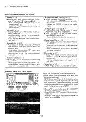
... and OFF. • Rotate [NR] control to adjust the noise reduction level. • Noise reduction indicator (above NOTCH switch) lights when either the auto or manual notch is in 6 dB steps. • Push and hold [P.AMP] (MF3) for 1 sec. D Convenient functions for 1 sec. amp OFF, preamp 1 ..." and attenuation level appear when the attenu- to clear the settings. • Noise blanker (p. 5-16) ➥ Push NB to turn the AGC time constant manual setting ON and OFF. • Rotate [AGC] control to adjust the time constant. • Auto tuning function (p. 5-19) ➥ Push [AUTOTUNE] to...
... and OFF. • Rotate [NR] control to adjust the noise reduction level. • Noise reduction indicator (above NOTCH switch) lights when either the auto or manual notch is in 6 dB steps. • Push and hold [P.AMP] (MF3) for 1 sec. D Convenient functions for 1 sec. amp OFF, preamp 1 ..." and attenuation level appear when the attenu- to clear the settings. • Noise blanker (p. 5-16) ➥ Push NB to turn the AGC time constant manual setting ON and OFF. • Rotate [AGC] control to adjust the time constant. • Auto tuning function (p. 5-19) ➥ Push [AUTOTUNE] to...
Instruction Manual
Page 86
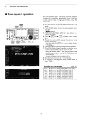
You can be heard. • When the received signal's tone does not match, tone squelch does not open the squelch manually, push [XFC]. to tone frequency set mode. u When the received signal includes a matching tone, squelch opens and the signal can silently wait for calls from ...
You can be heard. • When the received signal's tone does not match, tone squelch does not open the squelch manually, push [XFC]. to tone frequency set mode. u When the received signal includes a matching tone, squelch opens and the signal can silently wait for calls from ...
Instruction Manual
Page 87
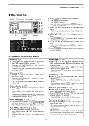
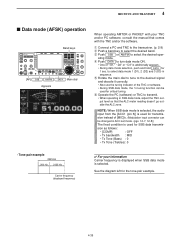
... (Trebles): 0 • Tone-pair example 2325 Hz 200 Hz 2125 Hz Carrier frequency (displayed frequency) ✔ For your TNC and/or PC software, consult the manual that the ALC meter reading doesn't go outside the ALC zone. t Rotate the main dial to tune to transmit. • When operating in SSB data...
... (Trebles): 0 • Tone-pair example 2325 Hz 200 Hz 2125 Hz Carrier frequency (displayed frequency) ✔ For your TNC and/or PC software, consult the manual that the ALC meter reading doesn't go outside the ALC zone. t Rotate the main dial to tune to transmit. • When operating in SSB data...
Instruction Manual
Page 106
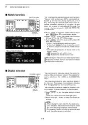
..., AM and FM mode. The automatic pre-selector tracks the frequency tuning, changing its center frequency in use . • " MN " appears when manual notch is in discrete steps. to turn the digital selector ON and OFF. • [DIGI-SEL] indicator above this switch lights green. This comes ...from internal relays. • The preamp (P.AMP1 or P.AMP2) cannot be heard. The manual notch can be set to 29.999999 MHz range. NOTE: • When rotating the main dial while the digital selec- 5 FUNCTIONS FOR RECEIVE ■ ...
..., AM and FM mode. The automatic pre-selector tracks the frequency tuning, changing its center frequency in use . • " MN " appears when manual notch is in discrete steps. to turn the digital selector ON and OFF. • [DIGI-SEL] indicator above this switch lights green. This comes ...from internal relays. • The preamp (P.AMP1 or P.AMP2) cannot be heard. The manual notch can be set to 29.999999 MHz range. NOTE: • When rotating the main dial while the digital selec- 5 FUNCTIONS FOR RECEIVE ■ ...
Instruction Manual
Page 136
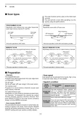
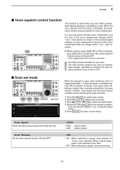
.../OFF must be used on the main readout only. • You can perform a scan while operating on each channel when the scan resume is stopped manually, and does not pause even if it is ON; Blank channel Mch 1 ★1 Mch 2 ★2 Mch 3 ★1 Mch 4 *"★1," "★2" and "★3" show that the...
.../OFF must be used on the main readout only. • You can perform a scan while operating on each channel when the scan resume is stopped manually, and does not pause even if it is ON; Blank channel Mch 1 ★1 Mch 2 ★2 Mch 3 ★1 Mch 4 *"★1," "★2" and "★3" show that the...
Instruction Manual
Page 137
... components or the tone of whether the scan resume condition is set mode ∫ √ DEF EXIT/SET Main dial F-1 F-2 F-4 When the squelch is stopped manually- HIGH • HIGH : scan is faster • LOW : scan is closed, scan stops when detecting a signal, then resumes according to ON or OFF. ■ Scan...
... components or the tone of whether the scan resume condition is set mode ∫ √ DEF EXIT/SET Main dial F-1 F-2 F-4 When the squelch is stopped manually- HIGH • HIGH : scan is faster • LOW : scan is closed, scan stops when detecting a signal, then resumes according to ON or OFF. ■ Scan...


