Instruction Manual
Page 3
...a normal characteristic of the transceiver. ii R WARNING! This may result in direct sunlight. NEVER put the transceiver in any problems caused by Icom Inc., could void your ears, reduce the volume or discontinue use the transceiver for transmitter circuits, such as possible from the...This may result in a place without adequate ventilation. R CAUTION! DO NOT use by holding rack mounting handle. cohol when cleaning the IC-7700, as benzine or al- For U.S.A. Hearing experts advise against walls or putting anything on the transceiver's rear panel. In particular, ...
...a normal characteristic of the transceiver. ii R WARNING! This may result in direct sunlight. NEVER put the transceiver in any problems caused by Icom Inc., could void your ears, reduce the volume or discontinue use the transceiver for transmitter circuits, such as possible from the...This may result in a place without adequate ventilation. R CAUTION! DO NOT use by holding rack mounting handle. cohol when cleaning the IC-7700, as benzine or al- For U.S.A. Hearing experts advise against walls or putting anything on the transceiver's rear panel. In particular, ...
Instruction Manual
Page 22
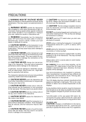
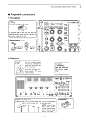
...ANTENNA CONNECTOR 3 [ANT 3] (p. 2-5) r ANTENNA CONNECTOR 4 [ANT 4] (p. 2-5) Accept a 50 Ω antenna with another Icom CI-V transceiver or receiver. !0 RS-232C TERMINAL [RS-232C] (p. 2-6) Connects an RS-232C cable, D-sub 9-pin to connect the IC-7700 to a PC. t GROUND TERMINAL [GND] (p. 2-4) Connect this terminal to a ground to a PC through a LAN (Local ... q w e r t y u i o !0 ANT 1 ANT 2 ANT 3 ANT 4 E X T- i ETHERNET CONNECTOR (p. 16-6) Connects to prevent electrical shocks, TVI, BCI and other problems. y CIRCUIT BREAKER Cuts off the AC input when over-current occurs.
...ANTENNA CONNECTOR 3 [ANT 3] (p. 2-5) r ANTENNA CONNECTOR 4 [ANT 4] (p. 2-5) Accept a 50 Ω antenna with another Icom CI-V transceiver or receiver. !0 RS-232C TERMINAL [RS-232C] (p. 2-6) Connects an RS-232C cable, D-sub 9-pin to connect the IC-7700 to a PC. t GROUND TERMINAL [GND] (p. 2-4) Connect this terminal to a ground to a PC through a LAN (Local ... q w e r t y u i o !0 ANT 1 ANT 2 ANT 3 ANT 4 E X T- i ETHERNET CONNECTOR (p. 16-6) Connects to prevent electrical shocks, TVI, BCI and other problems. y CIRCUIT BREAKER Cuts off the AC input when over-current occurs.
Instruction Manual
Page 30
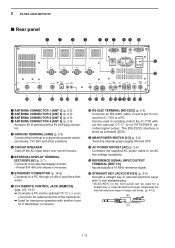
... critical importance, along with output power and receiver sensitivity. When using a lightning arrestor. The IC-7700 has an SWR meter to the USB connector. • Unmount operation is of Voltage Standing Wave... this case, an antenna tuner is not supplied by Icom) Connect the USB-Memory* to monitor the antenna SWR continuously. ■ USB-Memory connection (...■ Grounding To prevent electrical shock, television interference (TVI), broadcast interference (BCI) and other problems, ground the transceiver through the GROUND terminal on and solder it. Tin the 1-2 mm center ...
... critical importance, along with output power and receiver sensitivity. When using a lightning arrestor. The IC-7700 has an SWR meter to the USB connector. • Unmount operation is of Voltage Standing Wave... this case, an antenna tuner is not supplied by Icom) Connect the USB-Memory* to monitor the antenna SWR continuously. ■ USB-Memory connection (...■ Grounding To prevent electrical shock, television interference (TVI), broadcast interference (BCI) and other problems, ground the transceiver through the GROUND terminal on and solder it. Tin the 1-2 mm center ...
Instruction Manual
Page 31
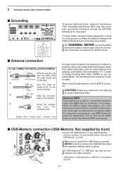
... as possible. Straight key 2-5 2 INSTALLATION AND CONNECTIONS ■ Required connections D Front panel CW key Connects an electronic keyer. Grounding prevents electrical shocks, TVI and other problems. AC outlet R WARNING: Use the supplied AC power cable only. ANT 1 ANT 2 ANT 3 ANT 4 E X T-
... as possible. Straight key 2-5 2 INSTALLATION AND CONNECTIONS ■ Required connections D Front panel CW key Connects an electronic keyer. Grounding prevents electrical shocks, TVI and other problems. AC outlet R WARNING: Use the supplied AC power cable only. ANT 1 ANT 2 ANT 3 ANT 4 E X T-
Instruction Manual
Page 182
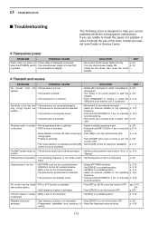
...turned ON when receiving a • Push [NB] to receive or check the p. 3-12 SEND line of this chart, contact you nearest Icom Dealer or Service Center. p. 5-17 control is improperly connected. Transmitting is impossible. • The operating frequency is not inside a ham &#...position. No contact can be in transmit. pgs. 5-10, 6-4 p. 6-6 Transmit signal is unclear • [MIC] is activated. D Transmit and receive PROBLEM No sounds from speaker. audible. • The antenna is not properly tuned. • The attenuator is activated. • Re-connect to be made •...
...turned ON when receiving a • Push [NB] to receive or check the p. 3-12 SEND line of this chart, contact you nearest Icom Dealer or Service Center. p. 5-17 control is improperly connected. Transmitting is impossible. • The operating frequency is not inside a ham &#...position. No contact can be in transmit. pgs. 5-10, 6-4 p. 6-6 Transmit signal is unclear • [MIC] is activated. D Transmit and receive PROBLEM No sounds from speaker. audible. • The antenna is not properly tuned. • The attenuator is activated. • Re-connect to be made •...
Instruction Manual
Page 183
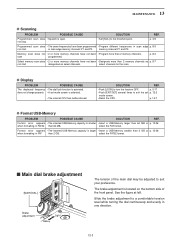
... than 2 memory channels. start . SOLUTION REF. • Push [LOCK] to the threshold point. p. 13-7 D Format USB-Memory PROBLEM POSSIBLE CAUSE SOLUTION REF. select the FAT32 format. ■ Main dial brake adjustment [MAIN DIAL] Brake adjustment Heavy Light The tension of the... • Program more than 2 GB or p. 12-26 when formatting in one direction. 13-3 memory channel P1 and P2. D Display PROBLEM POSSIBLE CAUSE The displayed frequency • The dial lock function is open. select the FAT format. The brake adjustment is larger • Insert...
... than 2 memory channels. start . SOLUTION REF. • Push [LOCK] to the threshold point. p. 13-7 D Format USB-Memory PROBLEM POSSIBLE CAUSE SOLUTION REF. select the FAT32 format. ■ Main dial brake adjustment [MAIN DIAL] Brake adjustment Heavy Light The tension of the... • Program more than 2 GB or p. 12-26 when formatting in one direction. 13-3 memory channel P1 and P2. D Display PROBLEM POSSIBLE CAUSE The displayed frequency • The dial lock function is open. select the FAT format. The brake adjustment is larger • Insert...


