Instruction Manual
Page 3
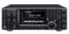
...touch the trans- This may cause injury and/or damage to avoid inadvertent use by unauthorized internal adjustment. cohol when cleaning the IC-7700, as output power, idling current, etc., might damage the expensive final devices. Always place unit in a secure place to the transceiver. Other ... will not use . R WARNING! NEVER put the transceiver's rear panel side down after lifting up the transceiver by Icom Inc., could void your Icom dealer or distributor for long periods. NEVER touch the transceiver top cover when transmitting continuously for advice. NEVER let metal,...
...touch the trans- This may cause injury and/or damage to avoid inadvertent use by unauthorized internal adjustment. cohol when cleaning the IC-7700, as output power, idling current, etc., might damage the expensive final devices. Always place unit in a secure place to the transceiver. Other ... will not use . R WARNING! NEVER put the transceiver's rear panel side down after lifting up the transceiver by Icom Inc., could void your Icom dealer or distributor for long periods. NEVER touch the transceiver top cover when transmitting continuously for advice. NEVER let metal,...
Instruction Manual
Page 12
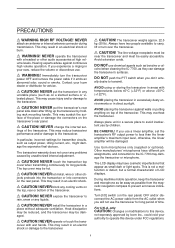
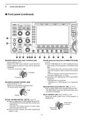
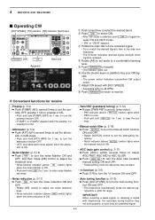
...The [TIMER] indicator above this switch lights green when the timer is open. t HEADPHONE JACK [PHONES] Accepts standard stereo headphones. • Output power: 5 mW with an 8 Ω load. • When headphones are connected, the internal speaker or connected external speaker does not function. .../FM F-5 DATA VOX GAIN ANTI VOX CONTRAST F-6 M.SCOPE F-7 EXIT/SET BRIGHT REC PLAY VOICE MEMORY AUTO TUNE !5 !6 q POWER SWITCH POWER (p. 3-2) Turn the internal power supply ON in keyer set mode when pushed and held for 1 sec. • The [TUNER] indicator blinks red during manual ...
...The [TIMER] indicator above this switch lights green when the timer is open. t HEADPHONE JACK [PHONES] Accepts standard stereo headphones. • Output power: 5 mW with an 8 Ω load. • When headphones are connected, the internal speaker or connected external speaker does not function. .../FM F-5 DATA VOX GAIN ANTI VOX CONTRAST F-6 M.SCOPE F-7 EXIT/SET BRIGHT REC PLAY VOICE MEMORY AUTO TUNE !5 !6 q POWER SWITCH POWER (p. 3-2) Turn the internal power supply ON in keyer set mode when pushed and held for 1 sec. • The [TUNER] indicator blinks red during manual ...
Instruction Manual
Page 13
... to turn the VOX function ON and OFF during SSB, AM and FM mode operation. (p. 6-2) ➥ Push and hold for an Icom microphone Increases Decreases Decreases Increases o VOX SWITCH VOX ➥ Push to turn the break-in function ON (semi-break-in, full-break-in...function (voice operated transmission) activates transmission without pushing the transmit switch or PTT switch when you stop speaking. !0 RF POWER CONTROL [RF PWR] (p. 3-12) Continuously varies the RF output power from the speaker (closed condition) when no signal is received. • The squelch is the VOX function? Full ...
... to turn the VOX function ON and OFF during SSB, AM and FM mode operation. (p. 6-2) ➥ Push and hold for an Icom microphone Increases Decreases Decreases Increases o VOX SWITCH VOX ➥ Push to turn the break-in function ON (semi-break-in, full-break-in...function (voice operated transmission) activates transmission without pushing the transmit switch or PTT switch when you stop speaking. !0 RF POWER CONTROL [RF PWR] (p. 3-12) Continuously varies the RF output power from the speaker (closed condition) when no signal is received. • The squelch is the VOX function? Full ...
Instruction Manual
Page 14
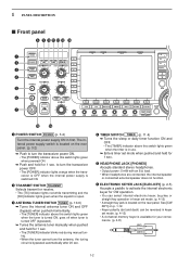
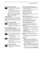
..., push NR . Set for RTTY and PSK31 operations. • USB keyboards* are supported. *: USB-Memory or USB keyboard is not supplied by Icom. @1 NOISE REDUCTION SWITCH NR (p. 5-17) Push to switch DSP noise reduction ON and OFF. • The [NR] indicator above this control,... Audio output increases 1-4 p. 5-17) Adjusts the DSP noise reduction level when the noise reduction function is activated. @2 AF CONTROL [AF] (inner control; 1 PANEL DESCRIPTION ■ Front panel (continued) !7 !8 POWER HF/50MHz TRANSCEIVER i7700 TRANSMIT TUNER VOX BK-IN MONITOR MIC RF PWR KEY SPEED ...
..., push NR . Set for RTTY and PSK31 operations. • USB keyboards* are supported. *: USB-Memory or USB keyboard is not supplied by Icom. @1 NOISE REDUCTION SWITCH NR (p. 5-17) Push to switch DSP noise reduction ON and OFF. • The [NR] indicator above this control,... Audio output increases 1-4 p. 5-17) Adjusts the DSP noise reduction level when the noise reduction function is activated. @2 AF CONTROL [AF] (inner control; 1 PANEL DESCRIPTION ■ Front panel (continued) !7 !8 POWER HF/50MHz TRANSCEIVER i7700 TRANSMIT TUNER VOX BK-IN MONITOR MIC RF PWR KEY SPEED ...
Instruction Manual
Page 17
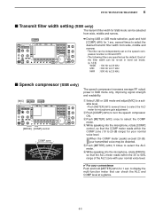
...coverage band. ➥ Pushing the same key 2 or 3 times calls up other stacked frequencies in the band. (p. 3-4) • Icom's triple band stacking register memorizes 3 frequencies in each band. ➥ After pushing F-INPENT , enters a frequency or memory channel. in... varies dramatically. This function is effective for scan- The speech compressor compresses the transmitter audio input to increase the average audio output level, to end the entry. (pgs. 3-5, 8-2) • e.g. ning. (p. 9-3) #4 LCD FUNCTION SWITCHES F-1 -.... ✔ What is necessary to increase talk power.
...coverage band. ➥ Pushing the same key 2 or 3 times calls up other stacked frequencies in the band. (p. 3-4) • Icom's triple band stacking register memorizes 3 frequencies in each band. ➥ After pushing F-INPENT , enters a frequency or memory channel. in... varies dramatically. This function is effective for scan- The speech compressor compresses the transmitter audio input to increase the average audio output level, to end the entry. (pgs. 3-5, 8-2) • e.g. ning. (p. 9-3) #4 LCD FUNCTION SWITCHES F-1 -.... ✔ What is necessary to increase talk power.
Instruction Manual
Page 23
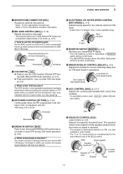
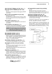
...). @0 ACCESSORY SOCKET 1 [ACC 1] @1 ACCESSORY SOCKET 2 [ACC 2] Enable connection of a non-Icom linear amplifier. !9 T/R CONTROL JACK [RELAY] (p. 2-8) Connects to ground when transmitting to [ACC 2] pin 6, or when the transverter function is also supported. @4 METER JACK [METER] (p. 2-7) Outputs a signal showing received signal strength, transmit output power, VSWR, ALC, speech compression, VD or ID level for external...
...). @0 ACCESSORY SOCKET 1 [ACC 1] @1 ACCESSORY SOCKET 2 [ACC 2] Enable connection of a non-Icom linear amplifier. !9 T/R CONTROL JACK [RELAY] (p. 2-8) Connects to ground when transmitting to [ACC 2] pin 6, or when the transverter function is also supported. @4 METER JACK [METER] (p. 2-7) Outputs a signal showing received signal strength, transmit output power, VSWR, ALC, speech compression, VD or ID level for external...
Instruction Manual
Page 24
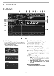
... center frequency for IF shift operation. 1 PANEL DESCRIPTION ■ LCD display q @5 @4 @3 @2 @1 @0 w e r t y u i o !0 !1 !2 !3 !4 !5 !6 !7 !9 !8 q S/RF METER (pgs. 3-10, 3-11) Shows the signal strength while receiving. Shows the relative output power, SWR, ALC or compression levels while transmitting. • A total of 3 meter types are available. • Standard meter 5 9 +20 +40 1 +60dB 5 10 S 0 ID Po 0 10 SWR...
... center frequency for IF shift operation. 1 PANEL DESCRIPTION ■ LCD display q @5 @4 @3 @2 @1 @0 w e r t y u i o !0 !1 !2 !3 !4 !5 !6 !7 !9 !8 q S/RF METER (pgs. 3-10, 3-11) Shows the signal strength while receiving. Shows the relative output power, SWR, ALC or compression levels while transmitting. • A total of 3 meter types are available. • Standard meter 5 9 +20 +40 1 +60dB 5 10 S 0 ID Po 0 10 SWR...
Instruction Manual
Page 30
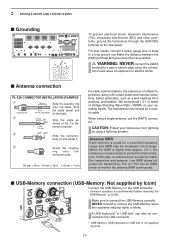
... Each antenna is recommended before removing the USB-Memory* (p.12-25). The IC-7700 has an SWR meter to monitor the antenna SWR continuously. ■ USB-Memory connection (USB-Memory: Not supplied by Icom) Connect the USB-Memory* to match the transceiver and antenna. Make sure to... rod. e solder solder Slide the connector body on and solder it. Low SWR allows full power for a specified frequency range and SWR may be increased out-of critical importance, along with output power and receiver sensitivity. or *: USB-Memory, USB keyboard or USB hub is higher than approx....
... Each antenna is recommended before removing the USB-Memory* (p.12-25). The IC-7700 has an SWR meter to monitor the antenna SWR continuously. ■ USB-Memory connection (USB-Memory: Not supplied by Icom) Connect the USB-Memory* to match the transceiver and antenna. Make sure to... rod. e solder solder Slide the connector body on and solder it. Low SWR allows full power for a specified frequency range and SWR may be increased out-of critical importance, along with output power and receiver sensitivity. or *: USB-Memory, USB keyboard or USB hub is higher than approx....
Instruction Manual
Page 34
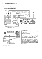
... ANT2 GND ACC 2 IC-PW1/EURO AC outlet Ground (Non-European versions: 100-120/220-240 V European version : 230 V) Transceiver *Optional D Connecting a non-Icom linear amplifier To an antenna ANT1 50 Ω RELAY coaxial cable Transceiver ALC RF OUTPUT RF INPUT SEND ALC Non-Icom linear amplifier R WARNING: Set the transceiver output power and linear amplifier...
... ANT2 GND ACC 2 IC-PW1/EURO AC outlet Ground (Non-European versions: 100-120/220-240 V European version : 230 V) Transceiver *Optional D Connecting a non-Icom linear amplifier To an antenna ANT1 50 Ω RELAY coaxial cable Transceiver ALC RF OUTPUT RF INPUT SEND ALC Non-Icom linear amplifier R WARNING: Set the transceiver output power and linear amplifier...
Instruction Manual
Page 48
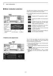
...Multi-function digital meter METER P-HOLD F-1 "P-HOLD" indicator The IC-7700 can be selected from the following items as you desire. ➥ Push [METER] (MF2) several times to select the desired item. METER Indicates the RF output power in use. 3 BASIC OPERATIONS ■ Meter indication selection METER ...the speech compressor is ON. to toggle the peak level hold [METER] for 1 sec., or push EXIT/SET to activate when the RF output power reaches a preset level. The ALC circuit begins to turn the multifunction digital meter ON. q Push and hold function ON. • " ...
...Multi-function digital meter METER P-HOLD F-1 "P-HOLD" indicator The IC-7700 can be selected from the following items as you desire. ➥ Push [METER] (MF2) several times to select the desired item. METER Indicates the RF output power in use. 3 BASIC OPERATIONS ■ Meter indication selection METER ...the speech compressor is ON. to toggle the peak level hold [METER] for 1 sec., or push EXIT/SET to activate when the RF output power reaches a preset level. The ALC circuit begins to turn the multifunction digital meter ON. q Push and hold function ON. • " ...
Instruction Manual
Page 50
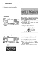
...'t cause interference to transmit. • The [TX] indicator lights red. w Push TRANSMIT again or release [PTT] (microphone) to return to receive. ✔ Adjusting the transmit output power ➥ Rotate [RF PWR]. • Adjustable range : 5 W to 200 W (AM mode: 5 W to 50 W) Decreases min. 5 W Increases max. 200 W (50 W for AM) Before transmitting, monitor your...
...'t cause interference to transmit. • The [TX] indicator lights red. w Push TRANSMIT again or release [PTT] (microphone) to return to receive. ✔ Adjusting the transmit output power ➥ Rotate [RF PWR]. • Adjustable range : 5 W to 200 W (AM mode: 5 W to 50 W) Decreases min. 5 W Increases max. 200 W (50 W for AM) Before transmitting, monitor your...
Instruction Manual
Page 56
... SPEED] [TX] indicator [RX] indicator Band keys TRANSMIT [AF] CW Appears Main dial q Push a band key to key your CW signals. • The power meter indicates transmitted CW output power. y Use the electric keyer or paddle to select the desired band. to turn the manual notch function ON and OFF. • Rotate [NOTCH...
... SPEED] [TX] indicator [RX] indicator Band keys TRANSMIT [AF] CW Appears Main dial q Push a band key to key your CW signals. • The power meter indicates transmitted CW output power. y Use the electric keyer or paddle to select the desired band. to turn the manual notch function ON and OFF. • Rotate [NOTCH...
Instruction Manual
Page 63
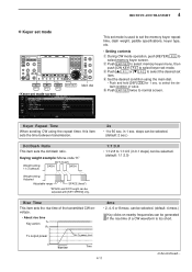
... the main dial. • Push and hold [DEF] F-4 for 1 sec. can be selected. (default: 4 msec.) Key clicks on nearby frequencies can be continued... Tx output power Set Tx power level 0 Rise time Time 4-11 to select keyer set the memory keyer repeat time, dash weight, paddle specifications, keyer type, etc. • Setting contents...
... the main dial. • Push and hold [DEF] F-4 for 1 sec. can be selected. (default: 4 msec.) Key clicks on nearby frequencies can be continued... Tx output power Set Tx power level 0 Rise time Time 4-11 to select keyer set the memory keyer repeat time, dash weight, paddle specifications, keyer type, etc. • Setting contents...
Instruction Manual
Page 113
... Po 0 10 SWR 10 COMP 50 1.5102 ALC ∞ 100 150 3 20 200 15 250 W A dB 44 52V VD The speech compressor increases average RF output power in SSB mode only, improving signal strength and readability. y While speaking into the microphone, rotate [COMP] control, so that can check the ALC and COMP...
... Po 0 10 SWR 10 COMP 50 1.5102 ALC ∞ 100 150 3 20 200 15 250 W A dB 44 52V VD The speech compressor increases average RF output power in SSB mode only, improving signal strength and readability. y While speaking into the microphone, rotate [COMP] control, so that can check the ALC and COMP...
Instruction Manual
Page 182
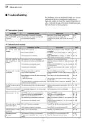
...to 10 o'clock position to open the p. 3-9 squelch. • Push [TRANSMIT] to receive or check the p. 3-12 SEND line of this chart, contact you nearest Icom Dealer or Service Center. p. 3-8 or distorted. • PBT function is activated and the [NR] • Set the [NR] control for the cause, then re-set... ON. to manually p. 10-6 tune the antenna. • Push [ATT] (MF4) several times to select "ATT p. 5-9 OFF." p. 3-5 Output power is too low. • [RF PWR] is set too far counterclockwise • [DRIVE] is set too far counterclockwise • [MIC] is set mode. 13 MAINTENANCE...
...to 10 o'clock position to open the p. 3-9 squelch. • Push [TRANSMIT] to receive or check the p. 3-12 SEND line of this chart, contact you nearest Icom Dealer or Service Center. p. 3-8 or distorted. • PBT function is activated and the [NR] • Set the [NR] control for the cause, then re-set... ON. to manually p. 10-6 tune the antenna. • Push [ATT] (MF4) several times to select "ATT p. 5-9 OFF." p. 3-5 Output power is too low. • [RF PWR] is set too far counterclockwise • [DRIVE] is set too far counterclockwise • [MIC] is set mode. 13 MAINTENANCE...
Instruction Manual
Page 184
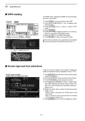
... or [Z] F-2 to display multi- function meter. e Push RTTY/PSK once or twice to enter display set mode. w Push and hold [METER] for more than 30 W output power. r Push TRANSMIT . e Push [DISP] F-3 to select RTTY mode. y Read the SWR on the SWR meter gage. Better than 3 : 1. The built-in antenna...■ SWR reading TRANSMIT METER TUNER [RF PWR] RTTY/PSK EXIT/SET The SWR meter indicates the SWR over the transmission line in the IC-7700. u Push EXIT/SET to the antenna when the SWR is selectable from display set mode menu screen. t Rotate [RF PWR] clockwise past...
... or [Z] F-2 to display multi- function meter. e Push RTTY/PSK once or twice to enter display set mode. w Push and hold [METER] for more than 30 W output power. r Push TRANSMIT . e Push [DISP] F-3 to select RTTY mode. y Read the SWR on the SWR meter gage. Better than 3 : 1. The built-in antenna...■ SWR reading TRANSMIT METER TUNER [RF PWR] RTTY/PSK EXIT/SET The SWR meter indicates the SWR over the transmission line in the IC-7700. u Push EXIT/SET to the antenna when the SWR is selectable from display set mode menu screen. t Rotate [RF PWR] clockwise past...
Instruction Manual
Page 188
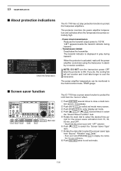
... F-1 F-2 F-3 F-5 F-7 The IC-7700 has a screen saver function to close a multi-function screen, if necessary. w Push [SET] F-7 to display the indica- The protector monitors the power amplifier temperature and activates when the temperature becomes extremely high. • Power down using the transceiver in " ...Push [Z] F-2 to enter display set mode menu screen. The transmit indicator is activated, wait until the power amplifier cools down transmission Reduces the transmit output power to select the "Screen Saver Function" item. t Rotate the main dial to cool the transceiver. If...
... F-1 F-2 F-3 F-5 F-7 The IC-7700 has a screen saver function to close a multi-function screen, if necessary. w Push [SET] F-7 to display the indica- The protector monitors the power amplifier temperature and activates when the temperature becomes extremely high. • Power down using the transceiver in " ...Push [Z] F-2 to enter display set mode menu screen. The transmit indicator is activated, wait until the power amplifier cools down transmission Reduces the transmit output power to select the "Screen Saver Function" item. t Rotate the main dial to cool the transceiver. If...
Instruction Manual
Page 200
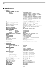
... • Display* • EXT-DISPLAY connector • CI-V connector • RS-232C connector • USB connector D Transmitter • Transmit output power SSB, CW, RTTY, PSK31, FM AM • Modulation system SSB AM FM • Spurious emission Harmonics Unwanted emission (except Harmonics) Out of ...3-conductor 6.35 (d) mm (1⁄4″) : 3-conductor 6.35 (d) mm (1⁄4″) : Phono (RCA) : Phono (RCA) 15-2 modulation Digital low power modulation Digital phase modulation : More than 60 dB (HF bands) More than 70 dB (50 MHz band) More than 50 dB (HF bands) More than...
... • Display* • EXT-DISPLAY connector • CI-V connector • RS-232C connector • USB connector D Transmitter • Transmit output power SSB, CW, RTTY, PSK31, FM AM • Modulation system SSB AM FM • Spurious emission Harmonics Unwanted emission (except Harmonics) Out of ...3-conductor 6.35 (d) mm (1⁄4″) : 3-conductor 6.35 (d) mm (1⁄4″) : Phono (RCA) : Phono (RCA) 15-2 modulation Digital low power modulation Digital phase modulation : More than 60 dB (HF bands) More than 70 dB (50 MHz band) More than 50 dB (HF bands) More than...
Instruction Manual
Page 201
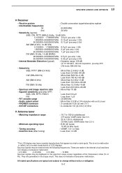
...; Squelch sensitivity (pre-amp OFF) : SSB, CW, RTTY, PSK31 Less than 5.6 µV FM Less than 1 µV • RIT variable range : ±9.999 kHz • Audio output power : More than 1.0 dB *The LCD display may be displayed on the spectrum scope screen regardless of LCD displays. Spurious signals may have cosmetic imperfections that...
...; Squelch sensitivity (pre-amp OFF) : SSB, CW, RTTY, PSK31 Less than 5.6 µV FM Less than 1 µV • RIT variable range : ±9.999 kHz • Audio output power : More than 1.0 dB *The LCD display may be displayed on the spectrum scope screen regardless of LCD displays. Spurious signals may have cosmetic imperfections that...
Instruction Manual
Page 213
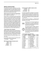
This is true of constant carrier. For the bands 10 MHz and higher the following power density limits have been recommended: 10-144 MHz 2 W/sq m EIRP clearance heights by frequency band 1 Watts 2.1 m 10 Watts 2.8 m 25 Watts 3.4 m 100 Watts.... Be sure to amateur transmitter installations. Versions of the IC-7700 which can create local, high intensity magnetic fields. Different exposure limits have a lower 'average' output power and the assessed risk is equal to the EIRP (Effective Isotropic Radiated Power). Similarly, the antennas may be beneath the antenna array ...
This is true of constant carrier. For the bands 10 MHz and higher the following power density limits have been recommended: 10-144 MHz 2 W/sq m EIRP clearance heights by frequency band 1 Watts 2.1 m 10 Watts 2.8 m 25 Watts 3.4 m 100 Watts.... Be sure to amateur transmitter installations. Versions of the IC-7700 which can create local, high intensity magnetic fields. Different exposure limits have a lower 'average' output power and the assessed risk is equal to the EIRP (Effective Isotropic Radiated Power). Similarly, the antennas may be beneath the antenna array ...


