
Instruction Manual
Page 2
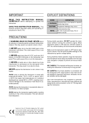
...battery will be damaged. Use Icom microphones only (supplied or optional). PRECAUTIONS R WARNING HIGH VOLTAGE! This may damage the transceiver. NOTE Inconvenience only. EXPLICIT DEFINITIONS WORD DEFINITION R WARNING Personal injury, fire hazard or electric shock may occur. Versions of the IC-718 which display the "CE" ... will obstruct heat dissipation. BE CAREFUL! Other manufacturer's microphones have different pin assignments, and connection to the IC-718 may result in areas with the European harmonised standard ETS300 684 JAN. 1997 (EMC product standard for the...
...battery will be damaged. Use Icom microphones only (supplied or optional). PRECAUTIONS R WARNING HIGH VOLTAGE! This may damage the transceiver. NOTE Inconvenience only. EXPLICIT DEFINITIONS WORD DEFINITION R WARNING Personal injury, fire hazard or electric shock may occur. Versions of the IC-718 which display the "CE" ... will obstruct heat dissipation. BE CAREFUL! Other manufacturer's microphones have different pin assignments, and connection to the IC-718 may result in areas with the European harmonised standard ETS300 684 JAN. 1997 (EMC product standard for the...
Instruction Manual
Page 13
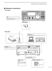
3 INSTALLATION AND CONNECTIONS s Advanced connections • Front panel MIC The AFSK modulation signal can be input from [MIC]. (p. 33) IC-718 MODE FIL TS PWR AF RF/SQL RIT SHIFT MIC PHONES LOCK 1 2 3 V/M A=B A/B 4 5 6 MW M - EXTERNAL SPEAKER (p. 55) SP-21, etc 11 ACC SOCKETS (p. 7) [SEND], [ALC] (p. 14) ... ∫ HEADPHONES • Rear panel AH-4 (p. 55) with AH-2b or long wire ANTENNA (p. 13) Connects a liner amprifier, etc. [REMOTE] (p. 57) Used for connecting a non-Icom linear amplifier.
3 INSTALLATION AND CONNECTIONS s Advanced connections • Front panel MIC The AFSK modulation signal can be input from [MIC]. (p. 33) IC-718 MODE FIL TS PWR AF RF/SQL RIT SHIFT MIC PHONES LOCK 1 2 3 V/M A=B A/B 4 5 6 MW M - EXTERNAL SPEAKER (p. 55) SP-21, etc 11 ACC SOCKETS (p. 7) [SEND], [ALC] (p. 14) ... ∫ HEADPHONES • Rear panel AH-4 (p. 55) with AH-2b or long wire ANTENNA (p. 13) Connects a liner amprifier, etc. [REMOTE] (p. 57) Used for connecting a non-Icom linear amplifier.
Instruction Manual
Page 14
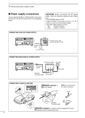
...of the power source is 12-15 V when you use a non-Icom power supply. • DC power cable polarity is correct. 3 INSTALLATION AND CONNECTIONS s Power supply connections Use an optional PS-85 DC POWER SUPPLY when operating the IC-718 with AC power. Crimp 12 V battery Supplied DC power cable Solder... 5678 1234 DC power socket Connect to a battery without supplied DC fuses, otherwise the fire hazard may occur. 12 DC power cable CONNECTING NON-ICOM DC POWER SUPPLY DC power supply AC outlet DC power 13.8 V 20 A socket _+ 13 9 10 11 12 5678 1234 AC cable _ black Supplied...
...of the power source is 12-15 V when you use a non-Icom power supply. • DC power cable polarity is correct. 3 INSTALLATION AND CONNECTIONS s Power supply connections Use an optional PS-85 DC POWER SUPPLY when operating the IC-718 with AC power. Crimp 12 V battery Supplied DC power cable Solder... 5678 1234 DC power socket Connect to a battery without supplied DC fuses, otherwise the fire hazard may occur. 12 DC power cable CONNECTING NON-ICOM DC POWER SUPPLY DC power supply AC outlet DC power 13.8 V 20 A socket _+ 13 9 10 11 12 5678 1234 AC cable _ black Supplied...
Instruction Manual
Page 16
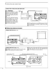
... the IC-718's power OFF when connecting the AT-180, otherwise, the CPU may malfunction and the AT-180 may not function properly. Nonmatched ALC and RF power settings could cause a fire or ruin the linear amplifier. To an antenna RF OUTPUT RF INPUT SEND ALC Non-Icom linear amplifier... 50 Ω coaxial cable ANT IC-718 SEND 13 9 10 11 12 5678 1234 ALC The specifications for the SEND relay are 16 V DC 2 A. Coaxial cable...
... the IC-718's power OFF when connecting the AT-180, otherwise, the CPU may malfunction and the AT-180 may not function properly. Nonmatched ALC and RF power settings could cause a fire or ruin the linear amplifier. To an antenna RF OUTPUT RF INPUT SEND ALC Non-Icom linear amplifier... 50 Ω coaxial cable ANT IC-718 SEND 13 9 10 11 12 5678 1234 ALC The specifications for the SEND relay are 16 V DC 2 A. Coaxial cable...
Instruction Manual
Page 49
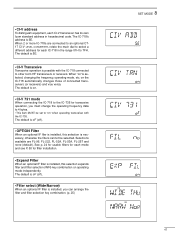
...for usable filters for each mode and see P. 50 for each CI-V transceiver has its own Icom standard address in the range 01H to 7FH. • CI-V address To distinguish equipment, each IC-718 in hexadecimal code. The default is oF (off ). • Filter select (Wide/Narrow) ...64257;ler is 5E. Selections available are connected to an optional CT17 CI-V LEVEL CONVERTER, rotate the main dial to other Icom HF transceivers or receivers. The IC-718's address is installed, this selection expands filter and filter selection (W/N) key combination on " when operating transceiver...
...for usable filters for each mode and see P. 50 for each CI-V transceiver has its own Icom standard address in the range 01H to 7FH. • CI-V address To distinguish equipment, each IC-718 in hexadecimal code. The default is oF (off ). • Filter select (Wide/Narrow) ...64257;ler is 5E. Selections available are connected to an optional CT17 CI-V LEVEL CONVERTER, rotate the main dial to other Icom HF transceivers or receivers. The IC-718's address is installed, this selection expands filter and filter selection (W/N) key combination on " when operating transceiver...
Instruction Manual
Page 59
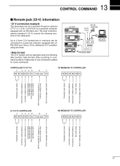
... of message code (fixed) Preamble code (fixed) Controller's default address Transceiver's default address OK code (fixed) End of message code (fixed) IC-718 TO CONTROLLER q wert y u FE FE E0 5E Cn Sc Data area FD NG MESSAGE TO CONTROLLER FE FE E0 5E FA FD Preamble code... address Transceiver's default address NG code (fixed) End of the transceiver. See p. 32 for some commands. The Icom Communications Interface-V (CI-V) controls the following data formats. Up to 4 Icom CI-V transceivers or receivers can be operated using set mode. • Data format The CI-V system can be ...
... of message code (fixed) Preamble code (fixed) Controller's default address Transceiver's default address OK code (fixed) End of message code (fixed) IC-718 TO CONTROLLER q wert y u FE FE E0 5E Cn Sc Data area FD NG MESSAGE TO CONTROLLER FE FE E0 5E FA FD Preamble code... address Transceiver's default address NG code (fixed) End of the transceiver. See p. 32 for some commands. The Icom Communications Interface-V (CI-V) controls the following data formats. Up to 4 Icom CI-V transceivers or receivers can be operated using set mode. • Data format The CI-V system can be ...


