
Instruction Manual
Page 2
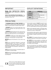
...Icom microphones only (supplied or optional). i NEVER attach an antenna or internal antenna connector during transmission. R NEVER let metal, wire or other objects touch any liquids. This may result in areas with the European harmonised standard ETS300 684 JAN. 1997 (EMC product standard for long periods. NEVER expose the transceiver to the IC-718...starting the vehicle. No risk of the IC-718 which display the "CE" symbol on a vehicle's dashboard can exceed 80°C (+176°F), resulting in direct sunlight. Make sure the transceiver power is OFF before attempting to the [...
...Icom microphones only (supplied or optional). i NEVER attach an antenna or internal antenna connector during transmission. R NEVER let metal, wire or other objects touch any liquids. This may result in areas with the European harmonised standard ETS300 684 JAN. 1997 (EMC product standard for long periods. NEVER expose the transceiver to the IC-718...starting the vehicle. No risk of the IC-718 which display the "CE" symbol on a vehicle's dashboard can exceed 80°C (+176°F), resulting in direct sunlight. Make sure the transceiver power is OFF before attempting to the [...

Instruction Manual
Page 3
... AND CONNECTIONS ......... 9 - 14 s Unpacking 9 s Selecting a location 9 s Grounding 9 s Antenna connection 9 s Required connections 10 s Advanced connections 11 s Power supply connections 12 s Liner amplifier connections 13 s External antenna tuners 14 4 FREQUENCY SETTING 15 - 19 s When first applying power 15 s Initial setting 15 s VFO description 16 s Frequency setting 17 s Dial lock function 19 5 RECEIVE...
... AND CONNECTIONS ......... 9 - 14 s Unpacking 9 s Selecting a location 9 s Grounding 9 s Antenna connection 9 s Required connections 10 s Advanced connections 11 s Power supply connections 12 s Liner amplifier connections 13 s External antenna tuners 14 4 FREQUENCY SETTING 15 - 19 s When first applying power 15 s Initial setting 15 s VFO description 16 s Frequency setting 17 s Dial lock function 19 5 RECEIVE...
Instruction Manual
Page 4
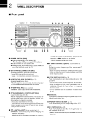
...The squelch re- tial set mode. (p. 41) Shifts the center frequency of the receivers's IF pass-band. 2 PANEL DESCRIPTION s Front panel Speaker Function Display @1 @0 !9 !8 !7 IC-718 MODE FIL TS 1 2 3 V/M A=B A/B 4 5 6 MW M -CL ˛ M V q PWR AF RF/SQL RIT SHIFT MIC PHONES w LOCK 7 8 9 SPL ...channel select function is turned on the display. • The shift frequency range is ±1.2 kHz. • Turn the optional DC power supply ON in advance. ➥ Push for microphone connector information. t RF GAIN/SQUELCH CONTROL [RF/SQL] (outer control; p. 21)...
...The squelch re- tial set mode. (p. 41) Shifts the center frequency of the receivers's IF pass-band. 2 PANEL DESCRIPTION s Front panel Speaker Function Display @1 @0 !9 !8 !7 IC-718 MODE FIL TS 1 2 3 V/M A=B A/B 4 5 6 MW M -CL ˛ M V q PWR AF RF/SQL RIT SHIFT MIC PHONES w LOCK 7 8 9 SPL ...channel select function is turned on the display. • The shift frequency range is ±1.2 kHz. • Turn the optional DC power supply ON in advance. ➥ Push for microphone connector information. t RF GAIN/SQUELCH CONTROL [RF/SQL] (outer control; p. 21)...
Instruction Manual
Page 8
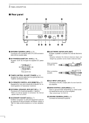
... q ANTENNA TERMINAL [ANT] (p. 10) Connects a 50 Ω antenna with a personal computer for remote operation of a non-Icom linear amplifier. w DC POWER SOCKET [DC 13.8V] (p. 12) Accepts 13.8V DC through the supplied DC power cable. r CI-V REMOTE CONTROL JACK [REMOTE] (p. 57) Designed for data communications or a liner amplifier, etc. t EXTERNAL SPEAKER...
... q ANTENNA TERMINAL [ANT] (p. 10) Connects a 50 Ω antenna with a personal computer for remote operation of a non-Icom linear amplifier. w DC POWER SOCKET [DC 13.8V] (p. 12) Accepts 13.8V DC through the supplied DC power cable. r CI-V REMOTE CONTROL JACK [REMOTE] (p. 57) Designed for data communications or a liner amplifier, etc. t EXTERNAL SPEAKER...
Instruction Manual
Page 11
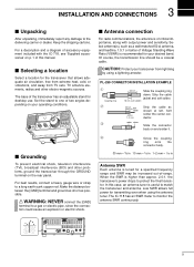
...cable as possible. In this manual. Set the stand to one of this case, an antenna tuner is higher than approx. 2.0:1, the transceiver's power drops to match the transceiver and antenna. For best results, connect a heavy gauge wire or strap to a gas or electric pipe, since ...in Antenna SWR Each antenna is of -range. Of course, the transmission line should be increased out-of critical importance, along with the IC-718, see 'Supplied accessories' on the rear panel. Slide the connector body on your transceiver from TV sets, TV antenna elements, radios and other problems, ground...
...cable as possible. In this manual. Set the stand to one of this case, an antenna tuner is higher than approx. 2.0:1, the transceiver's power drops to match the transceiver and antenna. For best results, connect a heavy gauge wire or strap to a gas or electric pipe, since ...in Antenna SWR Each antenna is of -range. Of course, the transmission line should be increased out-of critical importance, along with the IC-718, see 'Supplied accessories' on the rear panel. Slide the connector body on your transceiver from TV sets, TV antenna elements, radios and other problems, ground...
Instruction Manual
Page 12
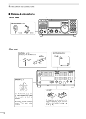
... SET P.AMP ATT TUNER ∫ CH DN UP √ • Rear panel ANTENNA (p. 56) [Example]: 1.8-30 MHz bands AH-710 approx. 24.5 m; 80.3 ft DC POWER SUPPLY PS-85 GROUND (p. 9) Use the heaviest gauge wire or strap available and make the connection as short as possible. Grounding prevents electrical shocks, TVI and... is turned OFF in "CW PADDL" in initial set mode. (p. 31) 3 INSTALLATION AND CONNECTIONS s Required connections • Front panel MICROPHONES (p. 55) HM-36 SM-20 IC-718 MODE FIL TS PWR AF RF/SQL RIT SHIFT MIC PHONES LOCK 1 2 3 V/M A=B A/B 4 5 6 MW M -
... SET P.AMP ATT TUNER ∫ CH DN UP √ • Rear panel ANTENNA (p. 56) [Example]: 1.8-30 MHz bands AH-710 approx. 24.5 m; 80.3 ft DC POWER SUPPLY PS-85 GROUND (p. 9) Use the heaviest gauge wire or strap available and make the connection as short as possible. Grounding prevents electrical shocks, TVI and... is turned OFF in "CW PADDL" in initial set mode. (p. 31) 3 INSTALLATION AND CONNECTIONS s Required connections • Front panel MICROPHONES (p. 55) HM-36 SM-20 IC-718 MODE FIL TS PWR AF RF/SQL RIT SHIFT MIC PHONES LOCK 1 2 3 V/M A=B A/B 4 5 6 MW M -
Instruction Manual
Page 14
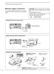
... a non-Icom power supply. • DC power cable polarity is correct. 3 INSTALLATION AND CONNECTIONS s Power supply connections Use an optional PS-85 DC POWER SUPPLY when operating the IC-718 with AC power. Crimp 12 V battery Supplied DC power cable Solder Fuses NEVER connect to a 24 V battery. _ black + red NOTE: Use terminals for the cable connections. DC power cable CONNECTING NON-ICOM DC POWER SUPPLY DC power supply AC...
... a non-Icom power supply. • DC power cable polarity is correct. 3 INSTALLATION AND CONNECTIONS s Power supply connections Use an optional PS-85 DC POWER SUPPLY when operating the IC-718 with AC power. Crimp 12 V battery Supplied DC power cable Solder Fuses NEVER connect to a 24 V battery. _ black + red NOTE: Use terminals for the cable connections. DC power cable CONNECTING NON-ICOM DC POWER SUPPLY DC power supply AC...
Instruction Manual
Page 16
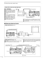
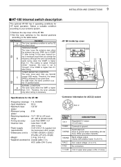
...;cations for the SEND relay are 16 V DC 2 A. Coaxial cable supplied with the AT-180 [ANT] ACC cable supplied with the AT-180 [ACC] one of two AT-180 [ACC] connectors HF antenna IC-718 13 9 10 11 12 5678 1234 Ground 14 Both tuners will not function... wire or optional AH-2b Coaxial cable (from the AH-4) Control cable IC-718 Ground Ground AH-4 CONNECTING THE AT-180 (p. 28) DO NOT! 3 INSTALLATION AND CONNECTIONS CONNECTING A NON-ICOM LINER AMPLIFIER R WARNING: Set the transceiver output power and linear amplifier ALC output level referring to -4 V, and the transceiver...
...;cations for the SEND relay are 16 V DC 2 A. Coaxial cable supplied with the AT-180 [ANT] ACC cable supplied with the AT-180 [ACC] one of two AT-180 [ACC] connectors HF antenna IC-718 13 9 10 11 12 5678 1234 Ground 14 Both tuners will not function... wire or optional AH-2b Coaxial cable (from the AH-4) Control cable IC-718 Ground Ground AH-4 CONNECTING THE AT-180 (p. 28) DO NOT! 3 INSTALLATION AND CONNECTIONS CONNECTING A NON-ICOM LINER AMPLIFIER R WARNING: Set the transceiver output power and linear amplifier ALC output level referring to -4 V, and the transceiver...
Instruction Manual
Page 50
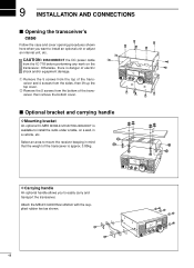
... HANDLE with the supplied rubber feet as shown. 48 q Remove the 5 screws from the top of the transceiver and 4 screws from the bottom of the transceiver, then remove the bottom cover. Select an area to mount the receiver keeping in a vehicle, etc. CAUTION: DISCONNECT the DC power cable from the IC-718 before performing... case and cover opening procedures shown here when you to easily carry and transport the transceiver. s Optional bracket and carrying handle D Mounting bracket An optional IC-MB5 MOBILE MOUNTING BRACKET is danger of the transceiver is approx. 3.80kg.
... HANDLE with the supplied rubber feet as shown. 48 q Remove the 5 screws from the top of the transceiver and 4 screws from the bottom of the transceiver, then remove the bottom cover. Select an area to mount the receiver keeping in a vehicle, etc. CAUTION: DISCONNECT the DC power cable from the IC-718 before performing... case and cover opening procedures shown here when you to easily carry and transport the transceiver. s Optional bracket and carrying handle D Mounting bracket An optional IC-MB5 MOBILE MOUNTING BRACKET is danger of the transceiver is approx. 3.80kg.
Instruction Manual
Page 53
... the AT-180 • Frequency coverage : 1.9 - 54 MHz • Input impedance : 50 Ω • Maximum input : 120 W power • Minimum tuning : 8 W power • Matching impedance : 16.7-150 Ω (HF band) range 20 -125 Ω (50 MHz band) • Tuning accuracy : Less...tuner is higher than 1.5:1. In this case, manual tuning is obtained at any given time. Goes to VSWR 3:1 after tuning) • Power supply : 13.8 V DC/1 A (supplied from requirements the transceiver's ACC socket) • Dimensions (mm/in) : 167(W) × 58.6(H) × 225(D) 69⁄16...
... the AT-180 • Frequency coverage : 1.9 - 54 MHz • Input impedance : 50 Ω • Maximum input : 120 W power • Minimum tuning : 8 W power • Matching impedance : 16.7-150 Ω (HF band) range 20 -125 Ω (50 MHz band) • Tuning accuracy : Less...tuner is higher than 1.5:1. In this case, manual tuning is obtained at any given time. Goes to VSWR 3:1 after tuning) • Power supply : 13.8 V DC/1 A (supplied from requirements the transceiver's ACC socket) • Dimensions (mm/in) : 167(W) × 58.6(H) × 225(D) 69⁄16...
Instruction Manual
Page 54
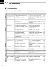
...POWER] to a suitable position. • Set [MIC GAIN] to a ham band. p. 21 pgs. 7 31, 32 Transmitted signals are installed in scan edge p. 40 not start . Programmed scan does • Squelch is activated. in the transmitting condition. • Check the SEND line of this chart, contact your nearest Icom...The same frequencies have not been • Program 2 or more memory channels. programmed. POWER PROBLEM POSSIBLE CAUSE Power does not come on • DC power cable is pushed. • Power Supply not turned ON. ble. memory channels P1 and P2. p. 42 p. 42 p. ...
...POWER] to a suitable position. • Set [MIC GAIN] to a ham band. p. 21 pgs. 7 31, 32 Transmitted signals are installed in scan edge p. 40 not start . Programmed scan does • Squelch is activated. in the transmitting condition. • Check the SEND line of this chart, contact your nearest Icom...The same frequencies have not been • Program 2 or more memory channels. programmed. POWER PROBLEM POSSIBLE CAUSE Power does not come on • DC power cable is pushed. • Power Supply not turned ON. ble. memory channels P1 and P2. p. 42 p. 42 p. ...
Instruction Manual
Page 56
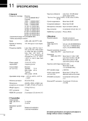
... All stated specifications are typical and subject to 60 min. after power on. audio 2.0 A Transmit Max. range : -10°C to +60°C; +14°F to +122°F) less than ±350 Hz. • Power supply requirement : 13.8 V DC ±15% (negative ground) •... Current drain (at +25°C (+77°F). below peak output power *Spurious freq.; to change without notice or obligation. at 13.8 V DC) : Receive Standby 1.3...
... All stated specifications are typical and subject to 60 min. after power on. audio 2.0 A Transmit Max. range : -10°C to +60°C; +14°F to +122°F) less than ±350 Hz. • Power supply requirement : 13.8 V DC ±15% (negative ground) •... Current drain (at +25°C (+77°F). below peak output power *Spurious freq.; to change without notice or obligation. at 13.8 V DC) : Receive Standby 1.3...
Instruction Manual
Page 57
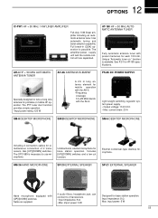
...switches and a low cut function. Has automatic tuning and band selection capability. The amplifier/power supply unit and the remote control unit are separated. Has [UP]/[DOWN] switches. 12 OPTIONS IC-PW1 HF + 50 MHz 1 KW LINER AMPLIFIER Full-duty 1 kW linear amplifier ...including an automatic antenna tuner. imput power: 5 W Designed for base station operation. Same as supplied. 4 audio filters; Unidirectional, electret microphone for base ...
...switches and a low cut function. Has automatic tuning and band selection capability. The amplifier/power supply unit and the remote control unit are separated. Has [UP]/[DOWN] switches. 12 OPTIONS IC-PW1 HF + 50 MHz 1 KW LINER AMPLIFIER Full-duty 1 kW linear amplifier ...including an automatic antenna tuner. imput power: 5 W Designed for base station operation. Same as supplied. 4 audio filters; Unidirectional, electret microphone for base ...


