

Instruction Manual
Page 3
...8 3 INSTALLATION AND CONNECTIONS ......... 9 - 14 s Unpacking 9 s Selecting a location 9 s Grounding 9 s Antenna connection 9 s Required connections 10 s Advanced connections 11 s Power supply connections 12 s Liner amplifier connections 13 s External antenna tuners 14 4 FREQUENCY SETTING 15 - 19 s When first applying...31 s Function for DC cable 1 r Fuse (FGB 4 A; internal use 1 er 1 q DC power cable 1 w Hand microphone (HM-36 1 e Fuse (FGB 20 A; Qty. for RTTY 33 6 MEMORY OPERATION 35 - 38 s Memory channels 35 s Memory channel selection 35 s Memory channel ...
...8 3 INSTALLATION AND CONNECTIONS ......... 9 - 14 s Unpacking 9 s Selecting a location 9 s Grounding 9 s Antenna connection 9 s Required connections 10 s Advanced connections 11 s Power supply connections 12 s Liner amplifier connections 13 s External antenna tuners 14 4 FREQUENCY SETTING 15 - 19 s When first applying...31 s Function for DC cable 1 r Fuse (FGB 4 A; internal use 1 er 1 q DC power cable 1 w Hand microphone (HM-36 1 e Fuse (FGB 20 A; Qty. for RTTY 33 6 MEMORY OPERATION 35 - 38 s Memory channels 35 s Memory channel selection 35 s Memory channel ...
Instruction Manual
Page 5
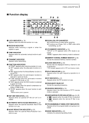
R]/[RTTY/RTTY-R]/[AM] (p. 20) Push to toggle an operating mode. • Push[MODE] for 2 sec. " " appears on the display....enters tuning step set mode. (p. 41) ➥ Push to toggle the meter function; (p. 26) • PO: indicates the relative RF output power. • ALC: Indicates ALC level. • SWR: indicates the SWR over the transmission line. !6 MIC COMPRESSOR SWITCH [COMP] (p. 27) Toggles... and [ANF] (option) switch. (p. 4) !8 NOISE BLANKER SWITCH [NB] (p. 22) ➥Toggles the noise blanker ON and OFF. during CW or RTTY mode, to toggle between CW and CW reverse or...
R]/[RTTY/RTTY-R]/[AM] (p. 20) Push to toggle an operating mode. • Push[MODE] for 2 sec. " " appears on the display....enters tuning step set mode. (p. 41) ➥ Push to toggle the meter function; (p. 26) • PO: indicates the relative RF output power. • ALC: Indicates ALC level. • SWR: indicates the SWR over the transmission line. !6 MIC COMPRESSOR SWITCH [COMP] (p. 27) Toggles... and [ANF] (option) switch. (p. 4) !8 NOISE BLANKER SWITCH [NB] (p. 22) ➥Toggles the noise blanker ON and OFF. during CW or RTTY mode, to toggle between CW and CW reverse or...
Instruction Manual
Page 7
...in use . !8 !7 !6 !5 !4 !2 !3 !0 !1 o SIGNAL/SQL/RF-GAIN METER ➥ Functions as an S-meter while receiving. ➥ Functions as a Power, ALC or SWR meter while transmitting. (p. 26) !0 VFO/MEMORY INDICATOR (p. 16) "VFO A" or "B" appears when VFO mode is paused. r TRANSMIT INDICATOR Appears while...when the speech compressor activates in use . !5 FREQUENCY READOUT Shows the operating frequency. !6 REVERSE INDICATOR (p.19) Appears when the CW reverse or RTTY reverse mode is selected. !7 WIDE/NARROW FILTER INDICATORS (pgs. 24, 25) ➥" " appears when the wide IF filter is ...
...in use . !8 !7 !6 !5 !4 !2 !3 !0 !1 o SIGNAL/SQL/RF-GAIN METER ➥ Functions as an S-meter while receiving. ➥ Functions as a Power, ALC or SWR meter while transmitting. (p. 26) !0 VFO/MEMORY INDICATOR (p. 16) "VFO A" or "B" appears when VFO mode is paused. r TRANSMIT INDICATOR Appears while...when the speech compressor activates in use . !5 FREQUENCY READOUT Shows the operating frequency. !6 REVERSE INDICATOR (p.19) Appears when the CW reverse or RTTY reverse mode is selected. !7 WIDE/NARROW FILTER INDICATORS (pgs. 24, 25) ➥" " appears when the wide IF filter is ...
Instruction Manual
Page 9
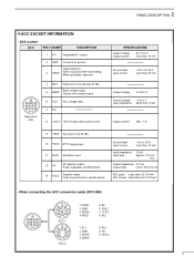
... 9 TKEY Key line for the optional AT-180. 5 BAND Band voltage output. (Varies with amateur band) 6 ALC ALC voltage input. 7 NC 8 13.8 V 13.8 V output when power is ON. When grounded, transmits. 13 9 10 11 12 5678 1234 Rear panel view 4 BDT Data line for the AT-180. 10 FSKK... RTTY keying input. 11 MOD Modulator input. 12 AF AF detector output. Input/output pin. 3 SEND Goes to ground when squelch opens. SPECIFICATIONS COLOR Output voltage ...
... 9 TKEY Key line for the optional AT-180. 5 BAND Band voltage output. (Varies with amateur band) 6 ALC ALC voltage input. 7 NC 8 13.8 V 13.8 V output when power is ON. When grounded, transmits. 13 9 10 11 12 5678 1234 Rear panel view 4 BDT Data line for the AT-180. 10 FSKK... RTTY keying input. 11 MOD Modulator input. 12 AF AF detector output. Input/output pin. 3 SEND Goes to ground when squelch opens. SPECIFICATIONS COLOR Output voltage ...
Instruction Manual
Page 27
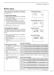
... set mode. y Rotate the tuning dial to exit initial set mode. FL-53A no THU (6 K) - - - FL-96 - - - - - - 52A (500) 53A (250) - - - RTTY - - - 52A (500) 53A (250) - - - 222 (1.8 K) - - - e Rotate the tuning dial to ON. w Push [UP Y] or [Z DN] one or more times until "... filter selecting r Push [UP Y] one or more times until "FIL" appears on operating modes. u Repeat steps t and y to select the desired mode. i Push [POWER] to select a filter. CW FL-222 no THU (6 K) no THU (6 K) no FL-52A SSB - - - FL-222 222 (1.8 K) 222 (1.8 K) FL...
... set mode. y Rotate the tuning dial to exit initial set mode. FL-53A no THU (6 K) - - - FL-96 - - - - - - 52A (500) 53A (250) - - - RTTY - - - 52A (500) 53A (250) - - - 222 (1.8 K) - - - e Rotate the tuning dial to ON. w Push [UP Y] or [Z DN] one or more times until "... filter selecting r Push [UP Y] one or more times until "FIL" appears on operating modes. u Repeat steps t and y to select the desired mode. i Push [POWER] to select a filter. CW FL-222 no THU (6 K) no THU (6 K) no FL-52A SSB - - - FL-222 222 (1.8 K) 222 (1.8 K) FL...
Instruction Manual
Page 28
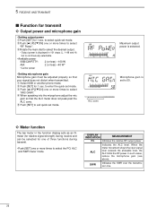
... the input signal level exceeds the allowable level, the ALC limits the RF power. q Select SSB or another phone mode. ALC zone Maximum output power is continuously selectable. • Available power SSB/CW/RTTY: 2 (or less) -100 W AM: 2 (or less) -40 W* *Carrier power • Setting microphone gain Microphone gain must be selected for 1 sec. r When...
... the input signal level exceeds the allowable level, the ALC limits the RF power. q Select SSB or another phone mode. ALC zone Maximum output power is continuously selectable. • Available power SSB/CW/RTTY: 2 (or less) -100 W AM: 2 (or less) -40 W* *Carrier power • Setting microphone gain Microphone gain must be selected for 1 sec. r When...
Instruction Manual
Page 32
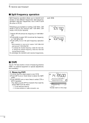
...to turn the split frequency operation ON. • Split operation is over 30 W. s SWR The IC-718 has a built-in VFO B. The best match is an example of measuring antenna SWR-no external equipment... or special adjustments are necessary. ï Measuring SWR q Confirm that the output power is now set for transmit). To exchange the transmit and receive frequencies, push [A/B]. then read ...; 1.5 check antenna or cable connection, etc. e Push [MODE] one or more times to select CW or RTTY operation. • Key down or push [PTT] to select the SWR meter. w Push [SET] one or...
...to turn the split frequency operation ON. • Split operation is over 30 W. s SWR The IC-718 has a built-in VFO B. The best match is an example of measuring antenna SWR-no external equipment... or special adjustments are necessary. ï Measuring SWR q Confirm that the output power is now set for transmit). To exchange the transmit and receive frequencies, push [A/B]. then read ...; 1.5 check antenna or cable connection, etc. e Push [MODE] one or more times to select CW or RTTY operation. • Key down or push [PTT] to select the SWR meter. w Push [SET] one or...
Instruction Manual
Page 56
... with an 8 Ω load • PHONES connector : 3-conductor 6.35 (d) mm (1⁄4˝) • External SP connector : 2-conductor 3.5 (d) mm (1⁄8˝)/8 Ω D Transmitter • Output power SSB, CW, RTTY AM • Modulation system SSB AM : 2-100 W 2-40 W : Balanced modulation Low level modulation 54 All stated specifications are typical and subject to...
... with an 8 Ω load • PHONES connector : 3-conductor 6.35 (d) mm (1⁄4˝) • External SP connector : 2-conductor 3.5 (d) mm (1⁄8˝)/8 Ω D Transmitter • Output power SSB, CW, RTTY AM • Modulation system SSB AM : 2-100 W 2-40 W : Balanced modulation Low level modulation 54 All stated specifications are typical and subject to...

