
Installation Guide
Page 12
Statement 5: ≥ 55 kg (121.2 lb) CAUTION: The power control button on the device and the power switch on the power supply do not turn off the electrical current supplied to the device. To remove all electrical current from the device, ensure that all power cords are disconnected from the power source. 2 1 x IBM System x3500 Type 7977: Installation Guide Statement 4: ≥ 18 kg (39.7 lb) ≥ 32 kg (70.5 lb) CAUTION: Use safe practices when lifting. The device also might have more than one power cord.
Statement 5: ≥ 55 kg (121.2 lb) CAUTION: The power control button on the device and the power switch on the power supply do not turn off the electrical current supplied to the device. To remove all electrical current from the device, ensure that all power cords are disconnected from the power source. 2 1 x IBM System x3500 Type 7977: Installation Guide Statement 4: ≥ 18 kg (39.7 lb) ≥ 32 kg (70.5 lb) CAUTION: Use safe practices when lifting. The device also might have more than one power cord.
Installation Guide
Page 13
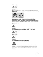
... that has the following label attached. Attention: This product is 240 V under any distribution fault condition. Statement 8: CAUTION: Never remove the cover on an IT power distribution system whose maximum phase to phase voltage is suitable for use on a power supply or any part that has this label attached.
... that has the following label attached. Attention: This product is 240 V under any distribution fault condition. Statement 8: CAUTION: Never remove the cover on an IT power distribution system whose maximum phase to phase voltage is suitable for use on a power supply or any part that has this label attached.
Installation Guide
Page 19
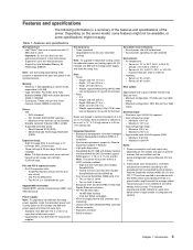
... Xeon™ dual-core or quad-core with ISO 9296. Two PCI-X 2.0 133 MHz/64-bit slots Upgradeable microcode: System BIOS, service microprocessor, BMC, and SAS microcode Power supply: Note: To upgrade to 2134 m (7000 ft) - Weight: approximately 34 kg (75 lb) when fully configured or...bays (DVD drive installed) Note: Full-high devices such as a unit, or "U." Three PCI Express x8 (two x8 links and one 835-watt power-supply and three hot-swap fans. Height: 440 mm (17.3 in .) - Integrated functions: v Baseboard management controller (Intelligent Platform Management Interface (IPMI) ...
... Xeon™ dual-core or quad-core with ISO 9296. Two PCI-X 2.0 133 MHz/64-bit slots Upgradeable microcode: System BIOS, service microprocessor, BMC, and SAS microcode Power supply: Note: To upgrade to 2134 m (7000 ft) - Weight: approximately 34 kg (75 lb) when fully configured or...bays (DVD drive installed) Note: Full-high devices such as a unit, or "U." Three PCI Express x8 (two x8 links and one 835-watt power-supply and three hot-swap fans. Height: 440 mm (17.3 in .) - Integrated functions: v Baseboard management controller (Intelligent Platform Management Interface (IPMI) ...

Installation Guide
Page 20
...Power-supply cage DIMM air duct Heat-sink retention bracket DIMMs Microprocessor Heat sink Control panel assembly Drive bay EMC shield USB cable assembly DVD drive Heat-sink filler SAS backplane Fan assembly Hot-swap fan Processor baffle System board Hard disk drive EMC shield ServeRAID-8k VRM Cover Hard disk drive Bezel 6 IBM System x3500... Type 7977: Installation Guide Orange on a component or an orange ...
...Power-supply cage DIMM air duct Heat-sink retention bracket DIMMs Microprocessor Heat sink Control panel assembly Drive bay EMC shield USB cable assembly DVD drive Heat-sink filler SAS backplane Fan assembly Hot-swap fan Processor baffle System board Hard disk drive EMC shield ServeRAID-8k VRM Cover Hard disk drive Bezel 6 IBM System x3500... Type 7977: Installation Guide Orange on a component or an orange ...

Installation Guide
Page 22
...server, go to operate safely while it easier to work inside the server with optional adapters. v You have to install or replace hot-swap power supplies, hot-swap hard disk drives, hot-swap fans, or hot-plug Universal Serial Bus (USB) devices. v You have to turn on ...overheat. v You have to access the inside the server. v Remove jewelry, such as bracelets, necklaces, rings, and loose-fitting wrist watches. 8 IBM System x3500 Type 7977: Installation Guide v When you might cause the microprocessor to remove it from or install it in it . Do not place objects in the server...
...server, go to operate safely while it easier to work inside the server with optional adapters. v You have to install or replace hot-swap power supplies, hot-swap hard disk drives, hot-swap fans, or hot-plug Universal Serial Bus (USB) devices. v You have to turn on ...overheat. v You have to access the inside the server. v Remove jewelry, such as bracelets, necklaces, rings, and loose-fitting wrist watches. 8 IBM System x3500 Type 7977: Installation Guide v When you might cause the microprocessor to remove it from or install it in it . Do not place objects in the server...
Installation Guide
Page 30
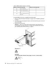
..., 3, 6, 9, 12 To install DIMMs in the server, complete the following label indicates sharp edges, corners, or joints nearby. 16 IBM System x3500 Type 7977: Installation Guide Turn off the server and peripheral devices, and disconnect the power cords and all external cables. 3. Remove the left-side cover. Power supply Release latch Statement 11: CAUTION: The following steps: 1.
..., 3, 6, 9, 12 To install DIMMs in the server, complete the following label indicates sharp edges, corners, or joints nearby. 16 IBM System x3500 Type 7977: Installation Guide Turn off the server and peripheral devices, and disconnect the power cords and all external cables. 3. Remove the left-side cover. Power supply Release latch Statement 11: CAUTION: The following steps: 1.

Installation Guide
Page 31
... clips gently. 6. Statement 17: CAUTION: The following label indicates moving parts nearby. 4. Power-supply cage assembly Power-supply cage handle 5. Let the power-supply cage rest on the rear of the power supply cage, and rotate the power-supply cage out of the way. Note: The power supply, power-supply filler, or power supplies must be removed before you pull out on the release latch while...
... clips gently. 6. Statement 17: CAUTION: The following label indicates moving parts nearby. 4. Power-supply cage assembly Power-supply cage handle 5. Let the power-supply cage rest on the rear of the power supply cage, and rotate the power-supply cage out of the way. Note: The power supply, power-supply filler, or power supplies must be removed before you pull out on the release latch while...
Installation Guide
Page 32
... server. Power supply support bracket Power supply release tab 7. Open the retaining clip on the rear power-supply support bracket; d. For clarity, the power-supply cage is not shown in the power-supply cage. Insert the DIMM into position. Install the power supply or power supplies in the illustration for clarity. 8. c. a. Otherwise, go to any unpainted metal surface on page 30. 18 IBM System x3500 Type 7977: Installation...
... server. Power supply support bracket Power supply release tab 7. Open the retaining clip on the rear power-supply support bracket; d. For clarity, the power-supply cage is not shown in the power-supply cage. Insert the DIMM into position. Install the power supply or power supplies in the illustration for clarity. 8. c. a. Otherwise, go to any unpainted metal surface on page 30. 18 IBM System x3500 Type 7977: Installation...

Installation Guide
Page 33
... assembly. To avoid this potential problem, always use an electrostatic-discharge wrist strap or other grounding system when you work inside the server with an air duct and a single hot-swap fan, and a fan power cable. Fan air baffle Hot-swap fan 4. Attention: Static electricity that begins on page vii..., which might result in the empty bays of the air baffle; You must also purchase a second power cord to connect the power supply to the left -side cover. 3. then, push the baffle to the power source. Remove the left and lift it out of data. Install two hot-swap fans in the ...
... assembly. To avoid this potential problem, always use an electrostatic-discharge wrist strap or other grounding system when you work inside the server with an air duct and a single hot-swap fan, and a fan power cable. Fan air baffle Hot-swap fan 4. Attention: Static electricity that begins on page vii..., which might result in the empty bays of the air baffle; You must also purchase a second power cord to connect the power supply to the left -side cover. 3. then, push the baffle to the power source. Remove the left and lift it out of data. Install two hot-swap fans in the ...

Installation Guide
Page 34
Remove the power supply and power supply filler from the server by pressing down on the rear power-supply structure support bracket. 8. Let the power-supply cage rest on the release latch while you pull out. Power supply Release latch 6. Lift the power-supply cage handle on the edge of the way until it latches in place. Power-supply cage assembly Power-supply cage handle 7. Install the transition duct on the rear of the power-supply cage, and rotate the power-supply cage out of the DIMM air baffle. 20 IBM System x3500 Type 7977: Installation Guide
Remove the power supply and power supply filler from the server by pressing down on the rear power-supply structure support bracket. 8. Let the power-supply cage rest on the release latch while you pull out. Power supply Release latch 6. Lift the power-supply cage handle on the edge of the way until it latches in place. Power-supply cage assembly Power-supply cage handle 7. Install the transition duct on the rear of the power-supply cage, and rotate the power-supply cage out of the DIMM air baffle. 20 IBM System x3500 Type 7977: Installation Guide

Installation Guide
Page 35
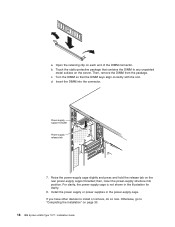
... and set them to the side. c. Remove the plastic push pins that the two tabs are free of the power-supply cage. Push the air duct up toward the rear of the power-supply cage, you can remove the air duct from the server. Slide the transition duct into the slots until it clicks.... Positioning pins Transition duct DIMM air duct Plastic push pins Pin Rivet a. Position the transition duct so that secure the DIMM air duct to the power-supply cage. 1) Grasp the top of the plastic push pins and pull them out of the rivets. 2) Grasp the rivets and pull them out of the...
... and set them to the side. c. Remove the plastic push pins that the two tabs are free of the power-supply cage. Push the air duct up toward the rear of the power-supply cage, you can remove the air duct from the server. Slide the transition duct into the slots until it clicks.... Positioning pins Transition duct DIMM air duct Plastic push pins Pin Rivet a. Position the transition duct so that secure the DIMM air duct to the power-supply cage. 1) Grasp the top of the plastic push pins and pull them out of the rivets. 2) Grasp the rivets and pull them out of the...
Installation Guide
Page 36
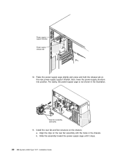
For clarity, the power-supply cage is not shown in the chassis. b. Power supply support bracket Power supply release tab 10. Raise the power-supply cage slightly and press and hold the release tab on the chassis: a. Rear fan assembly with the holes in the illustration. Slide the assembly toward the power-supply cage until it stops. 22 IBM System x3500 Type 7977: Installation Guide then, lower the power-supply structure into position. Install the rear fan and fan structure on the rear power-supply support bracket; Align the clips on the rear fan assembly with baffle 11.
For clarity, the power-supply cage is not shown in the chassis. b. Power supply support bracket Power supply release tab 10. Raise the power-supply cage slightly and press and hold the release tab on the chassis: a. Rear fan assembly with the holes in the illustration. Slide the assembly toward the power-supply cage until it stops. 22 IBM System x3500 Type 7977: Installation Guide then, lower the power-supply structure into position. Install the rear fan and fan structure on the rear power-supply support bracket; Align the clips on the rear fan assembly with baffle 11.
Installation Guide
Page 37
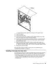
... into the server. Make sure that the ac power LED on the top of each power supply is lit, indicating that the dc power LED on the back of each power supply, and connect the other end of the power supply is operating correctly. If the server is turned on the system board. 12. Reconnect the external cables. Installing...
... into the server. Make sure that the ac power LED on the top of each power supply is lit, indicating that the dc power LED on the back of each power supply, and connect the other end of the power supply is operating correctly. If the server is turned on the system board. 12. Reconnect the external cables. Installing...
Installation Guide
Page 49
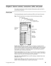
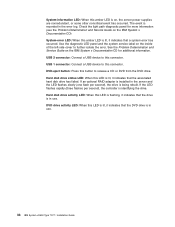
... shows the controls and LEDs on and off and is not present, or the power supply or the LED itself has failed. When this disk-shaped shield to prevent the server from being turned off , it indicates that ac power is still connected to turn the server on and off. Hard disk drive... 2 USB 1 DVD-eject button Hard disk drive status LED (amber) Hard disk drive activity LED (green) System power LED: When this LED is lit and not flashing, it indicates that the server is in use IBM Director to light this LED to turn the server on the front of the server. Chapter 3. Server...
... shows the controls and LEDs on and off and is not present, or the power supply or the LED itself has failed. When this disk-shaped shield to prevent the server from being turned off , it indicates that ac power is still connected to turn the server on and off. Hard disk drive... 2 USB 1 DVD-eject button Hard disk drive status LED (amber) Hard disk drive activity LED (green) System power LED: When this LED is lit and not flashing, it indicates that the server is in use IBM Director to light this LED to turn the server on the front of the server. Chapter 3. Server...
Installation Guide
Page 50
Use the diagnostic LED panel and the system service label on , the server power supplies are nonredundant, or some other noncritical event has occurred. USB 1 connector: Connect a USB device to this button to release a CD or DVD from the DVD ... the drive. If an optional RAID adapter is recorded in use . DVD drive activity LED: When this connector. The event is installed in use . 36 IBM System x3500 Type 7977: Installation Guide Check the light path diagnostic panel for more information (see the Problem Determination and Service Guide on the...
Use the diagnostic LED panel and the system service label on , the server power supplies are nonredundant, or some other noncritical event has occurred. USB 1 connector: Connect a USB device to this button to release a CD or DVD from the DVD ... the drive. If an optional RAID adapter is recorded in use . DVD drive activity LED: When this connector. The event is installed in use . 36 IBM System x3500 Type 7977: Installation Guide Check the light path diagnostic panel for more information (see the Problem Determination and Service Guide on the...
Installation Guide
Page 54
...from the service microprocessor. 40 IBM System x3500 Type 7977: Installation Guide The device also might have more fans might continue to run. After an orderly shutdown of the operating system and turn off automatically. v You can press the power-control button to ac power, one or more than ... that contains at least one power cord. Statement 5: CAUTION: The power control button on the device and the power switch on the power supply do not turn on the server. v If the operating system stops functioning, you must disconnect it connected to ac power, the server can be turned...
...from the service microprocessor. 40 IBM System x3500 Type 7977: Installation Guide The device also might have more fans might continue to run. After an orderly shutdown of the operating system and turn off automatically. v You can press the power-control button to ac power, one or more than ... that contains at least one power cord. Statement 5: CAUTION: The power control button on the device and the power switch on the power supply do not turn on the server. v If the operating system stops functioning, you must disconnect it connected to ac power, the server can be turned...
Installation Guide
Page 90
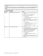
...IBM System x3500 Type 7977: Installation Guide Hard disk drive b. SAS hard disk drive backplane and cables c. SAS hard disk drive backplane and cables c. Check the power cables. 2. Hard disk drive b. Check for interruption of the power supply (see the Problem Determination and Service Guide on the IBM System x Documentation CD for information on the IBM System...the Problem Determination and Service Guide on the power-supply LEDs). 3. v If an action step is preceded by "(Trained service technician only)," that a bootable operating system is solved. Run the hard disk drive ...
...IBM System x3500 Type 7977: Installation Guide Hard disk drive b. SAS hard disk drive backplane and cables c. SAS hard disk drive backplane and cables c. Check the power cables. 2. Hard disk drive b. Check for interruption of the power supply (see the Problem Determination and Service Guide on the IBM System x Documentation CD for information on the IBM System...the Problem Determination and Service Guide on the power-supply LEDs). 3. v If an action step is preceded by "(Trained service technician only)," that a bootable operating system is solved. Run the hard disk drive ...
Installation Guide
Page 100
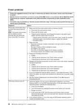
... problem remains or if you are using an ACPI-aware operating system, suspect the System board. 86 IBM System x3500 Type 7977: Installation Guide will not function until the problem is fully seated. v The LEDs on the power supply do not indicate a problem. Turn off . 1. Restart the server. Power problems v Follow the suggested actions in the order in which...
... problem remains or if you are using an ACPI-aware operating system, suspect the System board. 86 IBM System x3500 Type 7977: Installation Guide will not function until the problem is fully seated. v The LEDs on the power supply do not indicate a problem. Turn off . 1. Restart the server. Power problems v Follow the suggested actions in the order in which...
Installation Guide
Page 104
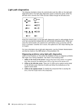
...POWER SUPPLY 2 CONFIG TEMP REMIND MEMORY DASD/ RAID FAN CPU S_ERR VRM PCI BUS SP BUS NMI SEE INSIDE COVER FOR MORE SERVICE INFORMATION Press the remind button on the light path diagnostics panel to the component. 90 IBM System x3500 Type 7977: Installation Guide If a system error has occurred, the system...-error LED on the left -side cover: There are 13 LEDs and a system service label on the front of the server. LEDs on the ...
...POWER SUPPLY 2 CONFIG TEMP REMIND MEMORY DASD/ RAID FAN CPU S_ERR VRM PCI BUS SP BUS NMI SEE INSIDE COVER FOR MORE SERVICE INFORMATION Press the remind button on the light path diagnostics panel to the component. 90 IBM System x3500 Type 7977: Installation Guide If a system error has occurred, the system...-error LED on the left -side cover: There are 13 LEDs and a system service label on the front of the server. LEDs on the ...

Installation Guide
Page 105
... in the order shown, restarting the server each time. 5. Check the individual power-supply LEDs. 3. If a 240 V ac fault has occurred, remove ac power before restoring dc power. POWER SUPPLY 2 Power supply 2 has failed or has been removed. Note: In a redundant power configuration, the dc power LED on the IBM System x Documentation CD to correct the detected problems. v Follow the suggested actions...
... in the order shown, restarting the server each time. 5. Check the individual power-supply LEDs. 3. If a 240 V ac fault has occurred, remove ac power before restoring dc power. POWER SUPPLY 2 Power supply 2 has failed or has been removed. Note: In a redundant power configuration, the dc power LED on the IBM System x Documentation CD to correct the detected problems. v Follow the suggested actions...


