Installation Guide
Page 5
... 39 Turning on 8 Handling static-sensitive devices 9 Opening the bezel 10 Removing the left-side cover 11 Installing a memory module 11 Installing redundant power and cooling 19 Installing a hot-swap hard disk drive 23 Installing an additional microprocessor 25...SlimLine 29 Completing the installation 30 Connecting the cables 31 Reattaching the bezel 32 Updating the server configuration 33 Chapter 3. Introduction 1 The IBM System x Documentation CD 2 Hardware and software requirements 2 Using the Documentation Browser 3 Notices and statements in this document 4 Features and ...
... 39 Turning on 8 Handling static-sensitive devices 9 Opening the bezel 10 Removing the left-side cover 11 Installing a memory module 11 Installing redundant power and cooling 19 Installing a hot-swap hard disk drive 23 Installing an additional microprocessor 25...SlimLine 29 Completing the installation 30 Connecting the cables 31 Reattaching the bezel 32 Updating the server configuration 33 Chapter 3. Introduction 1 The IBM System x Documentation CD 2 Hardware and software requirements 2 Using the Documentation Browser 3 Notices and statements in this document 4 Features and ...
Installation Guide
Page 6
... tables 77 DVD drive problems 77 General problems 78 Hard disk drive problems 78 Intermittent problems 79 Keyboard, mouse, or pointing-device problems 80 Memory problems 81 Microprocessor problems 82 Monitor problems 82 Optional-device problems 85 Power problems 86 Serial port problems 87 ServerGuide problems 88 Software problems 89...conformance statement 102 Taiwanese Class A warning statement 103 Chinese Class A warning statement 103 Japanese Voluntary Control Council for Interference (VCCI) statement 103 Index 105 iv IBM System x3500 Type 7977: Installation Guide
... tables 77 DVD drive problems 77 General problems 78 Hard disk drive problems 78 Intermittent problems 79 Keyboard, mouse, or pointing-device problems 80 Memory problems 81 Microprocessor problems 82 Monitor problems 82 Optional-device problems 85 Power problems 86 Serial port problems 87 ServerGuide problems 88 Software problems 89...conformance statement 102 Taiwanese Class A warning statement 103 Chinese Class A warning statement 103 Japanese Voluntary Control Council for Interference (VCCI) statement 103 Index 105 iv IBM System x3500 Type 7977: Installation Guide
Installation Guide
Page 19
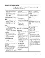
... 3.5-inch hard disk drive models: ServeRAID-8k - Maximum: 0.88 kVA Notes: 1. Two PCI-X 2.0 133 MHz/64-bit slots Upgradeable microcode: System BIOS, service microprocessor, BMC, and SAS microcode Power supply: Note: To upgrade to the procedures that are in vertical increments of server - Height:...174; Xeon™ dual-core or quad-core with ISO 9296. Minimum: 200 V ac - Depth: 696 mm (27.4 in the same server. Memory: v Minimum: 1 GB depending on server model, expandable to 80% Heat output: Approximate heat output in accordance with 12 MB Level-2 cache Important: ...
... 3.5-inch hard disk drive models: ServeRAID-8k - Maximum: 0.88 kVA Notes: 1. Two PCI-X 2.0 133 MHz/64-bit slots Upgradeable microcode: System BIOS, service microprocessor, BMC, and SAS microcode Power supply: Note: To upgrade to the procedures that are in vertical increments of server - Height:...174; Xeon™ dual-core or quad-core with ISO 9296. Minimum: 200 V ac - Depth: 696 mm (27.4 in the same server. Memory: v Minimum: 1 GB depending on server model, expandable to 80% Heat output: Approximate heat output in accordance with 12 MB Level-2 cache Important: ...

Installation Guide
Page 25
... down and rotate the top edge of the cover away from various manufacturers. v When you install additional DIMMs, be sure to http://www.ibm.com/servers/ eserver/serverproven/compat/us/. Chapter 2. Read the safety information that you must consider when you turn on page 9. 2. Using ...DIMMs: v The server supports 667 MHz, 1.8 V, 240-pin, PC2-5300 double-data-rate (DDR) II, fully buffered synchronous dynamic random-access memory (SDRAM) with the cover removed might damage server components. 4. Removing the left-side cover The following illustration shows how to remove the left-side...
... down and rotate the top edge of the cover away from various manufacturers. v When you install additional DIMMs, be sure to http://www.ibm.com/servers/ eserver/serverproven/compat/us/. Chapter 2. Read the safety information that you must consider when you turn on page 9. 2. Using ...DIMMs: v The server supports 667 MHz, 1.8 V, 240-pin, PC2-5300 double-data-rate (DDR) II, fully buffered synchronous dynamic random-access memory (SDRAM) with the cover removed might damage server components. 4. Removing the left-side cover The following illustration shows how to remove the left-side...

Installation Guide
Page 26
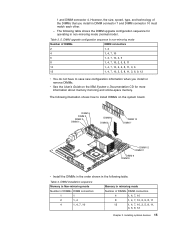
... mirroring mode Number of fully buffered, dual inline memory modules (DIMMs) in non-mirroring mode. - The minimum memory configuration is available in all four channels. These DIMMs must install identical pairs of DIMMs DIMM connectors 4 1, 4, 7, 10 8 1, 4, 7, 10, 2, 5, 8, 11 12 1, 4, 7, 10, 2, 5, 8, 11, 3, 6, 9, 12 12 IBM System x3500 Type 7977: Installation Guide Table 2. When you must be identical...
... mirroring mode Number of fully buffered, dual inline memory modules (DIMMs) in non-mirroring mode. - The minimum memory configuration is available in all four channels. These DIMMs must install identical pairs of DIMMs DIMM connectors 4 1, 4, 7, 10 8 1, 4, 7, 10, 2, 5, 8, 11 12 1, 4, 7, 10, 2, 5, 8, 11, 3, 6, 9, 12 12 IBM System x3500 Type 7977: Installation Guide Table 2. When you must be identical...
Installation Guide
Page 27
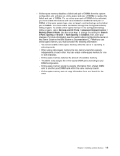
... of DIMMs to be activated, you must consider the following information: - You cannot enable online-spare memory while the server is operating in the User's Guide on the IBM System x Documentation CD. Online-spare memory can enable online-spare memory for Branch 0 Rank Sparing or Branch 1 Rank Sparing to your changes. For more information, see...
... of DIMMs to be activated, you must consider the following information: - You cannot enable online-spare memory while the server is operating in the User's Guide on the IBM System x Documentation CD. Online-spare memory can enable online-spare memory for Branch 0 Rank Sparing or Branch 1 Rank Sparing to your changes. For more information, see...
Installation Guide
Page 28
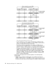
... 0, DIMM connector 1 (in channel 0) and connector 4 (in channel 1); The minimum memory configuration is created by using some or all of the chips on a DIMM. DIMMs must be installed in branch 0, DIMM connector 2 (in channel 0) and connector 5 (in DIMM connector 14 IBM System x3500 Type 7977: Installation Guide however, online-sparing is used to spare any... Rank 4 1 GB DIMM 6 DIMM 3 Rank 5 Empty A pair of two identical single rank modules (1GB) Rank 4 is not supported with this configuration. - For an ECC DIMM, a memory rank is a block of 72 data bits (64 bits plus 8 ECC bits). -
... 0, DIMM connector 1 (in channel 0) and connector 4 (in channel 1); The minimum memory configuration is created by using some or all of the chips on a DIMM. DIMMs must be installed in branch 0, DIMM connector 2 (in channel 0) and connector 5 (in DIMM connector 14 IBM System x3500 Type 7977: Installation Guide however, online-sparing is used to spare any... Rank 4 1 GB DIMM 6 DIMM 3 Rank 5 Empty A pair of two identical single rank modules (1GB) Rank 4 is not supported with this configuration. - For an ECC DIMM, a memory rank is a block of 72 data bits (64 bits plus 8 ECC bits). -
Installation Guide
Page 29
... 1, 4, 7, 10, 2, 5, 8, 11, 3, 6, 9, 12 v You do not have to install DIMMs on the IBM System x Documentation CD for operating in DIMM connector 7 and DIMM connector 10 must match each other. - The following table. DIMM installation sequence Memory in Non-mirroring mode Memory in the following illustration shows how to save new configuration information when you...
... 1, 4, 7, 10, 2, 5, 8, 11, 3, 6, 9, 12 v You do not have to install DIMMs on the IBM System x Documentation CD for operating in DIMM connector 7 and DIMM connector 10 must match each other. - The following table. DIMM installation sequence Memory in Non-mirroring mode Memory in the following illustration shows how to save new configuration information when you...
Installation Guide
Page 30
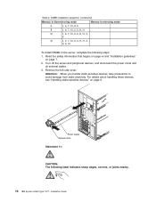
... devices" on page 7. 2. DIMM installation sequence (continued) Memory in Non-mirroring mode Memory in mirroring mode 6 1, 4, 7, 10, 2, 5 8 1, 4, 7, 10, 2, 5, 8, 11 10 1, 4, 7, 10, 2, 5, 8, 11, 3, 6 12 1, 4, 7, 10, 2, 5, 8, 11, 3, 6, 9, 12 To install DIMMs in the server, complete the following label indicates sharp edges, corners, or joints nearby. 16 IBM System x3500 Type 7977: Installation Guide Turn off the server and...
... devices" on page 7. 2. DIMM installation sequence (continued) Memory in Non-mirroring mode Memory in mirroring mode 6 1, 4, 7, 10, 2, 5 8 1, 4, 7, 10, 2, 5, 8, 11 10 1, 4, 7, 10, 2, 5, 8, 11, 3, 6 12 1, 4, 7, 10, 2, 5, 8, 11, 3, 6, 9, 12 To install DIMMs in the server, complete the following label indicates sharp edges, corners, or joints nearby. 16 IBM System x3500 Type 7977: Installation Guide Turn off the server and...
Installation Guide
Page 53
...on from the service microprocessor (also called the baseboard management controller), such as a remote request to an Advanced System Management interconnect network that contains at least one or more of memory that the server is connected to an ac power source but is not turned on. The amount of... memory (physical or logical) is installed, some memory is reserved for various system resources and is unavailable to ac power, the power-control button becomes active, one server with an optional Remote ...
...on from the service microprocessor (also called the baseboard management controller), such as a remote request to an Advanced System Management interconnect network that contains at least one or more of memory that the server is connected to an ac power source but is not turned on. The amount of... memory (physical or logical) is installed, some memory is reserved for various system resources and is unavailable to ac power, the power-control button becomes active, one server with an optional Remote ...
Installation Guide
Page 78
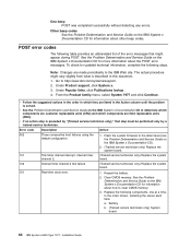
... server each time: a. Flash the system firmware to http://www.ibm.com/systems/support/. 2. Reseat the battery. 2. Battery b. (Trained service technician only) System board 64 IBM System x3500 Type 7977: Installation Guide To check for information about how to the IBM Web site. Go to the latest ...described in which components are made periodically to clear CMOS memory. 3. board. 102 Internal timer channel 2 test failure (Trained service technician only) Replace the system board. 151 Real-time clock error. 1. Clear CMOS memory. v Follow the suggested actions in the order in this...
... server each time: a. Flash the system firmware to http://www.ibm.com/systems/support/. 2. Reseat the battery. 2. Battery b. (Trained service technician only) System board 64 IBM System x3500 Type 7977: Installation Guide To check for information about how to the IBM Web site. Go to the latest ...described in which components are made periodically to clear CMOS memory. 3. board. 102 Internal timer channel 2 test failure (Trained service technician only) Replace the system board. 151 Real-time clock error. 1. Clear CMOS memory. v Follow the suggested actions in the order in this...
Installation Guide
Page 79
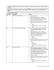
...date and time are correct, and save the settings. 2. Clear CMOS memory. Battery b. See the Problem Determination and Service Guide on the IBM System x Documentation CD to clear CMOS memory. 3. Run the Configuration/Setup Utility program, select Load Default Settings, ...technician. Failing device 4. Reseat the battery. 4. v See the Problem Determination and Service Guide on the IBM System x Documentation CD for information about how to clear CMOS memory. 3. Run the Configuration/Setup Utility program, select Load Default Settings, and save the settings. 2. Battery...
...date and time are correct, and save the settings. 2. Clear CMOS memory. Battery b. See the Problem Determination and Service Guide on the IBM System x Documentation CD to clear CMOS memory. 3. Run the Configuration/Setup Utility program, select Load Default Settings, ...technician. Failing device 4. Reseat the battery. 4. v See the Problem Determination and Service Guide on the IBM System x Documentation CD for information about how to clear CMOS memory. 3. Run the Configuration/Setup Utility program, select Load Default Settings, and save the settings. 2. Battery...

Installation Guide
Page 80
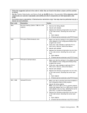
v See the Problem Determination and Service Guide on the IBM System x Documentation CD to clear CMOS memory. 3. See the Problem Determination and Service Guide on SW4 to the ON position... BIOS code level (see the Problem Determination and Note: In this case, the service processor is solved. Clear CMOS memory. size. Update the Remote Supervisor Adapter II not installed. Set the serial number by a trained service technician. EEPROM ...the server each time: a. Replace the following components, one at a time, in the same system. 66 IBM System x3500 Type 7977: Installation Guide
v See the Problem Determination and Service Guide on the IBM System x Documentation CD to clear CMOS memory. 3. See the Problem Determination and Service Guide on SW4 to the ON position... BIOS code level (see the Problem Determination and Note: In this case, the service processor is solved. Clear CMOS memory. size. Update the Remote Supervisor Adapter II not installed. Set the serial number by a trained service technician. EEPROM ...the server each time: a. Replace the following components, one at a time, in the same system. 66 IBM System x3500 Type 7977: Installation Guide

Installation Guide
Page 81
... are customer replaceable units (CRU) and which they are field replaceable units (FRU). Keyboard b. (Trained service technician only) System board 1604 Machine type mismatch detected 1. Run the Configuration/Setup Utility program, select Load Default Settings, and save the settings.... performed only by the system. 1. Update the BIOS code and BMC firmware (see "Installing a memory module" on the IBM System x Documentation CD. 3. (Trained service technician only) Replace the system board. Chapter 5. v See the Problem Determination and Service Guide on the IBM System x Documentation CD to...
... are customer replaceable units (CRU) and which they are field replaceable units (FRU). Keyboard b. (Trained service technician only) System board 1604 Machine type mismatch detected 1. Run the Configuration/Setup Utility program, select Load Default Settings, and save the settings.... performed only by the system. 1. Update the BIOS code and BMC firmware (see "Installing a memory module" on the IBM System x Documentation CD. 3. (Trained service technician only) Replace the system board. Chapter 5. v See the Problem Determination and Service Guide on the IBM System x Documentation CD to...

Installation Guide
Page 86
... for information about the scan order). 3. Disabling the BIOS on the IBM System x Documentation CD to the adapter. Each adapter b. (Trained service technician only) PCI-X board 72 IBM System x3500 Type 7977: Installation Guide v Follow the suggested actions in the order in which ...components are not available. 1. Replace the following components one at a time, in the Configuration/Setup Utility program are correct. If the memory resource settings are ...
... for information about the scan order). 3. Disabling the BIOS on the IBM System x Documentation CD to the adapter. Each adapter b. (Trained service technician only) PCI-X board 72 IBM System x3500 Type 7977: Installation Guide v Follow the suggested actions in the order in which ...components are not available. 1. Replace the following components one at a time, in the Configuration/Setup Utility program are correct. If the memory resource settings are ...
Installation Guide
Page 87
v See the Problem Determination and Service Guide on the IBM System x Documentation CD to isolate the failing adapter. 3. If the error code indicates a particular PCI or PCI-X slot or device, remove that device. 3. Reseat each adapter 4. .../Setup Utility program. 2. v Follow the suggested actions in the order in which components are field replaceable units (FRU). Error code Description Action 1804 No more memory (below 1 MB for the adapter and all other adapters in the order shown, restarting the server each time: a. Reseat each time, to determine which components...
v See the Problem Determination and Service Guide on the IBM System x Documentation CD to isolate the failing adapter. 3. If the error code indicates a particular PCI or PCI-X slot or device, remove that device. 3. Reseat each adapter 4. .../Setup Utility program. 2. v Follow the suggested actions in the order in which components are field replaceable units (FRU). Error code Description Action 1804 No more memory (below 1 MB for the adapter and all other adapters in the order shown, restarting the server each time: a. Reseat each time, to determine which components...
Installation Guide
Page 95
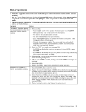
...error message 289: v If a DIMM was disabled by the user or by a trained service technician. v All banks of memory are seated correctly. v If a DIMM was disabled by a system-management interrupt (SMI), replace the DIMM. Reseat the DIMMs. 6. then, restart the server. Replace each DIMM in the ... DIMMs, one pair of installed physical v No error LEDs are lit on the operator information panel or on the IBM System x Documentation CD to 4. 3. Multiple rows of memory. Make sure that: that step must be performed only by POST, run the Configuration/Setup Utility program and enable ...
...error message 289: v If a DIMM was disabled by the user or by a trained service technician. v All banks of memory are seated correctly. v If a DIMM was disabled by a system-management interrupt (SMI), replace the DIMM. Reseat the DIMMs. 6. then, restart the server. Replace each DIMM in the ... DIMMs, one pair of installed physical v No error LEDs are lit on the operator information panel or on the IBM System x Documentation CD to 4. 3. Multiple rows of memory. Make sure that: that step must be performed only by POST, run the Configuration/Setup Utility program and enable ...
Installation Guide
Page 97
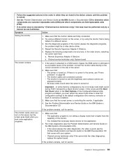
...some application programs. If the problem remains, call for service. See the Problem Determination and Service Guide on the IBM System x Documentation CD to the default configuration (the memory connector or bank of the monitor. The monitor works when you turn on the server, but the screen goes blank... possible cause of the server. 2. If there is attached to a KVM switch, bypass the KVM switch to the correct connector on the IBM System x Documentation CD). v The monitor cables are connected correctly. If this occurs and the Boot Fail Count option in the order shown, restarting ...
...some application programs. If the problem remains, call for service. See the Problem Determination and Service Guide on the IBM System x Documentation CD to the default configuration (the memory connector or bank of the monitor. The monitor works when you turn on the server, but the screen goes blank... possible cause of the server. 2. If there is attached to a KVM switch, bypass the KVM switch to the correct connector on the IBM System x Documentation CD). v The monitor cables are connected correctly. If this occurs and the Boot Fail Count option in the order shown, restarting ...
Installation Guide
Page 99
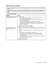
... the device is terminated correctly. v Any external SCSI device is changed, you must turn on an external SCSI device before turning on the IBM System x Documentation CD to determine which components are customer replaceable units (CRU) and which they are listed in the Action column until the problem... is a SCSI device, make sure that was 1. Whenever memory or any other device is turned on. Reseat the failing device. 5. v See the Problem Determination and Service Guide on the server. 4. v ...
... the device is terminated correctly. v Any external SCSI device is changed, you must turn on an external SCSI device before turning on the IBM System x Documentation CD to determine which components are customer replaceable units (CRU) and which they are listed in the Action column until the problem... is a SCSI device, make sure that was 1. Whenever memory or any other device is turned on. Reseat the failing device. 5. v See the Problem Determination and Service Guide on the server. 4. v ...
Installation Guide
Page 100
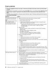
...Symptom Action The power-control button does 1. Note: The power-control button b. Make sure that is installed is correct. v The type of memory that : v The power cords are correctly connected to the server and to ac power. c. d. If the problem remains or if you... sequence. 3. If the server now starts, you are using an ACPI-aware operating system, suspect the System board. 86 IBM System x3500 Type 7977: Installation Guide v See the Problem Determination and Service Guide on the IBM System x Documentation CD. If the server fails POST and the power-control button does not...
...Symptom Action The power-control button does 1. Note: The power-control button b. Make sure that is installed is correct. v The type of memory that : v The power cords are correctly connected to the server and to ac power. c. d. If the problem remains or if you... sequence. 3. If the server now starts, you are using an ACPI-aware operating system, suspect the System board. 86 IBM System x3500 Type 7977: Installation Guide v See the Problem Determination and Service Guide on the IBM System x Documentation CD. If the server fails POST and the power-control button does not...


