
Service Guide
Page 3
... du ministère des Communications du Canada . viii Canadian Department of Communications Compliance Statement viii VCCI Statement viii Radio Protection for RS/6000 7025 F50 Series 1-9 Specifications 1-10 Power Cables 1-12 Service Inspection Guide 1-13 Chapter 2. Reference Information 1-1 System Unit Locations 1-1 System Data Flow 1-8 Typical Boot Sequence for Germany ix...
... du ministère des Communications du Canada . viii Canadian Department of Communications Compliance Statement viii VCCI Statement viii Radio Protection for RS/6000 7025 F50 Series 1-9 Specifications 1-10 Power Cables 1-12 Service Inspection Guide 1-13 Chapter 2. Reference Information 1-1 System Unit Locations 1-1 System Data Flow 1-8 Typical Boot Sequence for Germany ix...

Service Guide
Page 15
... Procedures (MAPs) that are not common to other systems. MAPs that are common to all systems are available for purchase: The IBM RS/6000 7025 F50 Series User's Guide contains information to the system unit, adapters, and attached devices that do not have their own service information.... Related Publications The following publications are contained in the IBM RS/6000 Diagnostic Information for Multiple Bus Systems. The Site and Hardware ...
... Procedures (MAPs) that are not common to other systems. MAPs that are common to all systems are available for purchase: The IBM RS/6000 7025 F50 Series User's Guide contains information to the system unit, adapters, and attached devices that do not have their own service information.... Related Publications The following publications are contained in the IBM RS/6000 Diagnostic Information for Multiple Bus Systems. The Site and Hardware ...
Service Guide
Page 25
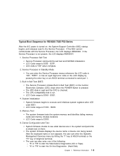
..." key (if Graphics terminal). The system firmware displays the device name or device icon being tested. Reference Information 1-9 Typical Boot Sequence for RS/6000 7025 F50 Series After the A/C power is E000 - LCD Code range is turned on the Central Electronics Complex (CEC) chips when the POWER Button is "OK" when...
..." key (if Graphics terminal). The system firmware displays the device name or device icon being tested. Reference Information 1-9 Typical Boot Sequence for RS/6000 7025 F50 Series After the A/C power is E000 - LCD Code range is turned on the Central Electronics Complex (CEC) chips when the POWER Button is "OK" when...

Service Guide
Page 131
...) to the disk drive modules. The path continues through the disk drive modules, then returns through two SSA links to a second connector on 7025 Model F50, since they support the internal and external SSA cable options. The SSA Adapter The system unit can be attached to FRU Index 3-59 The adapter...
...) to the disk drive modules. The path continues through the disk drive modules, then returns through two SSA links to a second connector on 7025 Model F50, since they support the internal and external SSA cable options. The SSA Adapter The system unit can be attached to FRU Index 3-59 The adapter...

Service Guide
Page 302
Refer to "Service Processor Reboot/Restart Recovery" on system failure B-24 Service Guide The RS/6000 7025 F50 Series supports the following section discusses some of these events becomes excessive, signalling a bigger problem. The Use OS-Defined restart policy is set to call ...
Refer to "Service Processor Reboot/Restart Recovery" on system failure B-24 Service Guide The RS/6000 7025 F50 Series supports the following section discusses some of these events becomes excessive, signalling a bigger problem. The Use OS-Defined restart policy is set to call ...
