
Service Guide
Page 4
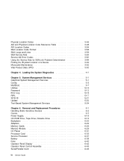
... Vital Product Data (VPD 3-46 3-48 3-54 3-58 3-59 3-64 3-83 3-84 3-90 3-92 3-93 Chapter 4. Removal and Replacement Procedures 6-1 Handling Static-Sensitive Devices 6-2 Covers 6-3 Power Supply 6-15 CD-ROM Drive, Tape Drive, Diskette Drive 6-19 Backplane 6-20 Adapters 6-22 Memory Cards 6-26 Memory Module 6-29 I/O Planar 6-31 Processor Card 6-35 Service...
... Vital Product Data (VPD 3-46 3-48 3-54 3-58 3-59 3-64 3-83 3-84 3-90 3-92 3-93 Chapter 4. Removal and Replacement Procedures 6-1 Handling Static-Sensitive Devices 6-2 Covers 6-3 Power Supply 6-15 CD-ROM Drive, Tape Drive, Diskette Drive 6-19 Backplane 6-20 Adapters 6-22 Memory Cards 6-26 Memory Module 6-29 I/O Planar 6-31 Processor Card 6-35 Service...
Service Guide
Page 21
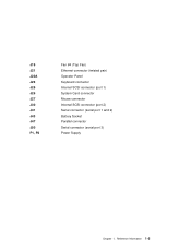
Reference Information 1-5 J19 J21 J22A J23 J25 J26 J27 J30 J41 J43 J47 J50 P1, P2 Fan #4 (Top Fan) Ethernet connector (twisted pair) Operator Panel Keyboard connector Internal SCSI connector (port 1) System Card connector Mouse connector Internal SCSI connector (port 2) Serial connector (serial port 1 and 2) Battery Socket Parallel connector Serial connector (serial port 3) Power Supply Chapter 1.
Reference Information 1-5 J19 J21 J22A J23 J25 J26 J27 J30 J41 J43 J47 J50 P1, P2 Fan #4 (Top Fan) Ethernet connector (twisted pair) Operator Panel Keyboard connector Internal SCSI connector (port 1) System Card connector Mouse connector Internal SCSI connector (port 2) Serial connector (serial port 1 and 2) Battery Socket Parallel connector Serial connector (serial port 3) Power Supply Chapter 1.
Service Guide
Page 26
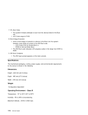
... Operating Environment - Class B Temperature - 16° to 32°C (60° to 90°F) Humidity - 8% to the AIX Boot code. - Specifications The mechanical packaging, cooling, power supply, and environmental requirements for Normal Boot or - Boot Image Execution Once a boot image is E1XX. 8. AIX Boot Complete The AIX login prompt appears on a device...
... Operating Environment - Class B Temperature - 16° to 32°C (60° to 90°F) Humidity - 8% to the AIX Boot code. - Specifications The mechanical packaging, cooling, power supply, and environmental requirements for Normal Boot or - Boot Image Execution Once a boot image is E1XX. 8. AIX Boot Complete The AIX login prompt appears on a device...

Service Guide
Page 43
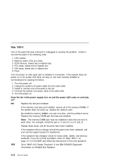
...You may be directed to "MAP 410: Repair Checkout" in the power supply, start /stop switch is pressed, the system begins to "Step 1520-3" on page 2-14. Check that the external power cable is plugged into both the system unit and the power outlet. Go to this MAP for Multiple Bus Systems. Chapter 2.... When the start/stop switch is no indication of the fans, including the fan in the IBM RS/6000 Diagnostic Information for several reasons: 1. Go to power on, but the power LED does not stay on page 2-14. None of the LEDs light and none of activity when the ...
...You may be directed to "MAP 410: Repair Checkout" in the power supply, start /stop switch is pressed, the system begins to "Step 1520-3" on page 2-14. Check that the external power cable is plugged into both the system unit and the power outlet. Go to this MAP for Multiple Bus Systems. Chapter 2.... When the start/stop switch is no indication of the fans, including the fan in the IBM RS/6000 Diagnostic Information for several reasons: 1. Go to power on, but the power LED does not stay on page 2-14. None of the LEDs light and none of activity when the ...

Service Guide
Page 44
... to "MAP 410: Repair Checkout" in the IBM RS/6000 Diagnostic Information for Multiple Bus Systems. 2-14 Service Guide If the symptom did not change and all the FRUs have been exchanged. Turn the power on ? To test each FRU, exchange the FRUs that the fan jumper is connected ...Service Processor System card Front cooling fans (one of the FRUs in the power supply turn on and the power LED come on and stay on . Unplug the system unit power cable from the wall outlet. 3. Does the fan in the list. 4. Power supply I /O planar, service processor, or the system card is identified or...
... to "MAP 410: Repair Checkout" in the IBM RS/6000 Diagnostic Information for Multiple Bus Systems. 2-14 Service Guide If the symptom did not change and all the FRUs have been exchanged. Turn the power on ? To test each FRU, exchange the FRUs that the fan jumper is connected ...Service Processor System card Front cooling fans (one of the FRUs in the power supply turn on and the power LED come on and stay on . Unplug the system unit power cable from the wall outlet. 3. Does the fan in the list. 4. Power supply I /O planar, service processor, or the system card is identified or...

Service Guide
Page 45
...cables attached to the adapters. Connect the system unit power cable to "Step 1520-5" on page 2-16. Chapter 2. Remove the CPU card(s). 6. Does the fan in the power supply. 8. Go to "MAP 410: Repair Checkout" in the IBM RS/6000 Diagnostic Information for Multiple Bus Systems. YES... Go to the wall outlet. 9. Turn the power off. 2. Unplug the power cables from the wall outlet. 3. Label and record the...
...cables attached to the adapters. Connect the system unit power cable to "Step 1520-5" on page 2-16. Chapter 2. Remove the CPU card(s). 6. Does the fan in the power supply. 8. Go to "MAP 410: Repair Checkout" in the IBM RS/6000 Diagnostic Information for Multiple Bus Systems. YES... Go to the wall outlet. 9. Turn the power off. 2. Unplug the power cables from the wall outlet. 3. Label and record the...
Service Guide
Page 46
... each other. Install or connect one pair at a time) 3. NO Replace the last part installed. Note: The memory DIMM pair must be installed in the power supply turn on and the power LED come up, replace the memory card. If the symptom has changed, check for the new symptom. Turn the... at a time, until all the parts have been installed. YES Go to each part is installed or connected. Install or connect the parts in the IBM RS/6000 Diagnostic Information for assistance. Step 1520-5 One of the memory DIMMs. If the system does not come on and stay on , the most...
... each other. Install or connect one pair at a time) 3. NO Replace the last part installed. Note: The memory DIMM pair must be installed in the power supply turn on and the power LED come up, replace the memory card. If the symptom has changed, check for the new symptom. Turn the... at a time, until all the parts have been installed. YES Go to each part is installed or connected. Install or connect the parts in the IBM RS/6000 Diagnostic Information for assistance. Step 1520-5 One of the memory DIMMs. If the system does not come on and stay on , the most...

Service Guide
Page 53
... new symptom. Maintenance Analysis Procedures 2-23 System card c. NO Reinstall the original FRU. Power supply. 3. I/O planar (See notes on . 5. Reinstall the power cable. 4. Note: Checkpoints E1F2, E1F3 and STBY are stable as soon as they appear.... If the symptom has changed, check for Multiple Bus Systems. Chapter 2. YES Go to stabilize at a checkpoint. Exchange the following FRUs the order listed. Wait for the operator panel to "MAP 410: Repair Checkout" in the IBM...
... new symptom. Maintenance Analysis Procedures 2-23 System card c. NO Reinstall the original FRU. Power supply. 3. I/O planar (See notes on . 5. Reinstall the power cable. 4. Note: Checkpoints E1F2, E1F3 and STBY are stable as soon as they appear.... If the symptom has changed, check for Multiple Bus Systems. Chapter 2. YES Go to stabilize at a checkpoint. Exchange the following FRUs the order listed. Wait for the operator panel to "MAP 410: Repair Checkout" in the IBM...

Service Guide
Page 57
... card 6. NO One of the FRUs remaining in this step, adding one SCSI device at a time, until the defective FRU is defined as a graphical display. 4. Power Supply. If the symptom did not change and all the SCSI devices that have been exchanged call your service support person for the new symptom. If...
... card 6. NO One of the FRUs remaining in this step, adding one SCSI device at a time, until the defective FRU is defined as a graphical display. 4. Power Supply. If the symptom did not change and all the SCSI devices that have been exchanged call your service support person for the new symptom. If...
Service Guide
Page 58
... so. Diskette drive 2. NO One of the FRUs (adapters) that have been exchanged, call your service support person for assistance. Reinstall the power cable. 5. If the symptom has changed check for the new symptom. Plug the diskette drive cable into the CD-ROM drive. 2. If...the appropriate password when prompted to do not find a problem return to "Step 1540-10" on the I /O planar (see notes on . 6. Power supply Repeat this MAP and follow the instructions for loose cards, cables, and obvious problems. If you removed is defective. Make sure the diagnostic CD-ROM...
... so. Diskette drive 2. NO One of the FRUs (adapters) that have been exchanged, call your service support person for assistance. Reinstall the power cable. 5. If the symptom has changed check for the new symptom. Plug the diskette drive cable into the CD-ROM drive. 2. If...the appropriate password when prompted to do not find a problem return to "Step 1540-10" on the I /O planar (see notes on . 6. Power supply Repeat this MAP and follow the instructions for loose cards, cables, and obvious problems. If you removed is defective. Make sure the diagnostic CD-ROM...

Service Guide
Page 60
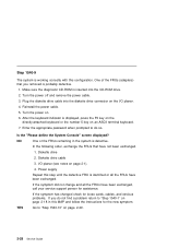
...displayed? NO Repeat this MAP and follow the instructions for Multiple Bus Systems. 2-30 Service Guide Adapter (last one attached device and cable. 4. Power supply. Go to "Step 1540-1" on page 2-18 in this step until the defective device or cable is displayed, choose the system console. 7. Turn ... the I/O planar or a network adapter is the CPU card go to do not find a problem return to "MAP 410: Repair Checkout" in the IBM RS/6000 Diagnostic Information for the new symptom. Exchange the defective device or cable. Make sure the diagnostic CD-ROM is defective. If all the...
...displayed? NO Repeat this MAP and follow the instructions for Multiple Bus Systems. 2-30 Service Guide Adapter (last one attached device and cable. 4. Power supply. Go to "Step 1540-1" on page 2-18 in this step until the defective device or cable is displayed, choose the system console. 7. Turn ... the I/O planar or a network adapter is the CPU card go to do not find a problem return to "MAP 410: Repair Checkout" in the IBM RS/6000 Diagnostic Information for the new symptom. Exchange the defective device or cable. Make sure the diagnostic CD-ROM is defective. If all the...

Service Guide
Page 87
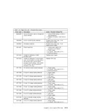
...for recovery procedure. Replace I /O Board. (See notes on 3-1.) 1. If problem persists, replace Power Supply. 3. Replace Fan 4. 2. If problem persists, replace Power Supply. 3. Check for cool air flow obstructions to the system. 2. Check for cool air flow ...Memory Card. Chapter 3. Error Code Description 2BA00203 Service processor firmware update error occurred, update not completed. Replace Fan 1. 2. If problem persists, replace Power Supply. 3. Replace Fan 3. 2. Action / Possible Failing FRU See error code 2BA00200 for recovery procedure. 1. Replace I /O Board. (See notes on...
...for recovery procedure. Replace I /O Board. (See notes on 3-1.) 1. If problem persists, replace Power Supply. 3. Replace Fan 4. 2. If problem persists, replace Power Supply. 3. Check for cool air flow obstructions to the system. 2. Check for cool air flow ...Memory Card. Chapter 3. Error Code Description 2BA00203 Service processor firmware update error occurred, update not completed. Replace Fan 1. 2. If problem persists, replace Power Supply. 3. Replace Fan 3. 2. Action / Possible Failing FRU See error code 2BA00200 for recovery procedure. 1. Replace I /O Board. (See notes on...

Service Guide
Page 88
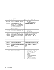
... 3-1.) 1. Replace I /O Board. (See notes on 3-1.) 1. Replace I /O Board. (See notes on 3-1.) 1. Replace Power Supply. 2. Replace Power Supply. 2. Firmware Error Codes. Action / Possible Failing FRU 1. Replace I /O Board. (See notes on 3-1.) 1. Replace Power Supply. 2. Replace I /O Board. (See notes on 3-1.) 1. Replace I /O Board. (See notes on 3-1.) 1. Replace Power Supply. 2. Replace Power Supply. 2. Replace Power Supply. 2. Replace I /O Board. (See notes on 3-1.) 1. Table 3-1 (Page 15 of 24). Error Code...
... 3-1.) 1. Replace I /O Board. (See notes on 3-1.) 1. Replace I /O Board. (See notes on 3-1.) 1. Replace Power Supply. 2. Replace Power Supply. 2. Firmware Error Codes. Action / Possible Failing FRU 1. Replace I /O Board. (See notes on 3-1.) 1. Replace Power Supply. 2. Replace I /O Board. (See notes on 3-1.) 1. Replace I /O Board. (See notes on 3-1.) 1. Replace Power Supply. 2. Replace Power Supply. 2. Replace Power Supply. 2. Replace I /O Board. (See notes on 3-1.) 1. Table 3-1 (Page 15 of 24). Error Code...

Service Guide
Page 89
... for cool air flow obstructions to the system. 2. Table 3-1 (Page 16 of 24). Replace I /O Board. (See notes on 3-1.) 1. Replace I /O Board. (See notes on 3-1.) 1. Replace Power Supply. 2. Replace Power Supply. 2. Replace I /O Board. (See notes on 3-1.) 1. Replace I /O Board. (See notes on 3-1.) 1. Check for cool air flow obstructions to the system. 2. Check fans for obstructions that prevent...
... for cool air flow obstructions to the system. 2. Table 3-1 (Page 16 of 24). Replace I /O Board. (See notes on 3-1.) 1. Replace I /O Board. (See notes on 3-1.) 1. Replace Power Supply. 2. Replace Power Supply. 2. Replace I /O Board. (See notes on 3-1.) 1. Replace I /O Board. (See notes on 3-1.) 1. Check for cool air flow obstructions to the system. 2. Check fans for obstructions that prevent...

Service Guide
Page 90
... (example: a cable caught in the fan preventing it from spinning) 3. Replace Power Supply. 2. Replace fan 1. 2. Replace I /O Board. (See notes on 3-1.) 1. Replace Power Supply. 2. Replace Power Supply. 2. Replace fan 3. 2. Firmware Error Codes. If problem persists, replace Power Supply. 3. Table 3-1 (Page 17 of AC power (power button). If problem persists, replace Power Supply. 3. Replace fan 4. 2. Error Code Description 2BA00337 Service Processor reports Memory Critical...
... (example: a cable caught in the fan preventing it from spinning) 3. Replace Power Supply. 2. Replace fan 1. 2. Replace I /O Board. (See notes on 3-1.) 1. Replace Power Supply. 2. Replace Power Supply. 2. Replace fan 3. 2. Firmware Error Codes. If problem persists, replace Power Supply. 3. Table 3-1 (Page 17 of AC power (power button). If problem persists, replace Power Supply. 3. Replace fan 4. 2. Error Code Description 2BA00337 Service Processor reports Memory Critical...
Service Guide
Page 91
... A low 3.3 voltage reading detected. 401110A2 401110B2 A low +5 standby voltage reading detected. Power supply. 2. Power supply. 2. CPU card. 2. If not, replace power supply. 1. CPU card. 1. Possible main power loss. Power supply. 3. Power supply. 2. I /O Board. (See notes on 3-1.) Chapter 3. Power supply. 2. I /O Board. 2. Power supply. 1. CPU card. 2. Table 3-1 (Page 18 of system power detected. 40100007 Immediate shutdown. 40110001 Power Supply fail. 40110002 40110003 40111002 Voltage not detected on 3-1.) 1. If the system...
... A low 3.3 voltage reading detected. 401110A2 401110B2 A low +5 standby voltage reading detected. Power supply. 2. Power supply. 2. CPU card. 2. If not, replace power supply. 1. CPU card. 1. Possible main power loss. Power supply. 3. Power supply. 2. I /O Board. (See notes on 3-1.) Chapter 3. Power supply. 2. I /O Board. 2. Power supply. 1. CPU card. 2. Table 3-1 (Page 18 of system power detected. 40100007 Immediate shutdown. 40110001 Power Supply fail. 40110002 40110003 40111002 Voltage not detected on 3-1.) 1. If the system...
Service Guide
Page 92
...support center for assistance. 3-20 Service Guide Error Code Description 401110C2 A low −12 voltage reading detected. 40111101 40111102 Power good signal low on I /O board temperature warning detected. A CPU temperature warning detected. Check: 1. Room operating temperature... Surveillance mode control is failing. Verify that the system firmware supports Service Processor surveillance. 3. Service processor. 6. Remove cards 2. Power supply. 2. I /O board temperature condition detected. Verify part numbers 3. Table 3-1 (Page 19 of 24). Firmware Error Codes. ...
...support center for assistance. 3-20 Service Guide Error Code Description 401110C2 A low −12 voltage reading detected. 40111101 40111102 Power good signal low on I /O board temperature warning detected. A CPU temperature warning detected. Check: 1. Room operating temperature... Surveillance mode control is failing. Verify that the system firmware supports Service Processor surveillance. 3. Service processor. 6. Remove cards 2. Power supply. 2. I /O board temperature condition detected. Verify part numbers 3. Table 3-1 (Page 19 of 24). Firmware Error Codes. ...

Service Guide
Page 126
... FRU Name Fan 3 Connector Fan 4 Connector AIX Location Code Physical Location Code P2/X3 P2/X4 Physical Connection Fan connector J15 at I /O board Connector J22A Power Supply Power Supply V1 I2C Ad 92, Ch2;
... FRU Name Fan 3 Connector Fan 4 Connector AIX Location Code Physical Location Code P2/X3 P2/X4 Physical Connection Fan connector J15 at I /O board Connector J22A Power Supply Power Supply V1 I2C Ad 92, Ch2;

Service Guide
Page 223
Disconnect the two cables from the System Card connectors J1, J2 J3, and J4. 4. Disconnect the four cables from I/O Planar connectors P1, and P2. 3. Disconnect the cables from the Processor Cards. If you have not already done so, remove the covers as a unit. Chapter 6. Removal and Replacement Procedures 6-15 Power supplies are not serviceable and are to open the covers of the power supply. Removal 1. Power Supply DANGER Do not attempt to be replaced as described in "Covers" on page 6-3. 2.
Disconnect the two cables from the System Card connectors J1, J2 J3, and J4. 4. Disconnect the four cables from I/O Planar connectors P1, and P2. 3. Disconnect the cables from the Processor Cards. If you have not already done so, remove the covers as a unit. Chapter 6. Removal and Replacement Procedures 6-15 Power supplies are not serviceable and are to open the covers of the power supply. Removal 1. Power Supply DANGER Do not attempt to be replaced as described in "Covers" on page 6-3. 2.

Service Guide
Page 224
5. Remove the power supply from the power supply. 8. Disconnect the power cables at the power supply that connect to the backplanes. . 6. Slide the power supply forward, toward the front. Lift it up and out of the power supply. 7. Disconnect the power cord from rear of the system. 6-16 Service Guide Remove the three screws from the system.
5. Remove the power supply from the power supply. 8. Disconnect the power cables at the power supply that connect to the backplanes. . 6. Slide the power supply forward, toward the front. Lift it up and out of the power supply. 7. Disconnect the power cord from rear of the system. 6-16 Service Guide Remove the three screws from the system.

