

Service Guide
Page 32
...PLEASE WAIT..." Symptom You need to isolate the problem. is still powered on page 2-6. Go to the Fast Path MAP in the IBM RS/6000 Diagnostic Information for possible operating system fault indications. Go to "E1xx Code Boot Problems" on the system console, the system ...graphic display) or device mnemonics (ASCII terminal) that appear during the power-on self-test (POST). You have OK displayed The Service Processor (SP) is waiting for Multiple Bus Systems. The system POST indicators are displayed on self-test (POST). 1. The term "POST indicators" refer ...
...PLEASE WAIT..." Symptom You need to isolate the problem. is still powered on page 2-6. Go to the Fast Path MAP in the IBM RS/6000 Diagnostic Information for possible operating system fault indications. Go to "E1xx Code Boot Problems" on the system console, the system ...graphic display) or device mnemonics (ASCII terminal) that appear during the power-on self-test (POST). You have OK displayed The Service Processor (SP) is waiting for Multiple Bus Systems. The system POST indicators are displayed on self-test (POST). 1. The term "POST indicators" refer ...

Service Guide
Page 34
... panel displays 2 sets of numbers, use the bottom set of the SCSI controller or adapter with the character "E0xx" then go to "SP Checkpoints" on the system. The SMS configuration list or Boot sequence selection menu shows more than are displayed on the operator panel within a ...I /O planar is replaced.) Note: In a "Twin-tailed" configuration where there is the last three digits of the four-digit number displayed in the IBM RS/6000 Diagnostic Information for Multiple Bus Systems. 2-4 Service Guide If problem not resolved, replace in conflict: 1. For all other numbers record SRN 101...
... panel displays 2 sets of numbers, use the bottom set of the SCSI controller or adapter with the character "E0xx" then go to "SP Checkpoints" on the system. The SMS configuration list or Boot sequence selection menu shows more than are displayed on the operator panel within a ...I /O planar is replaced.) Note: In a "Twin-tailed" configuration where there is the last three digits of the four-digit number displayed in the IBM RS/6000 Diagnostic Information for Multiple Bus Systems. 2-4 Service Guide If problem not resolved, replace in conflict: 1. For all other numbers record SRN 101...

Service Guide
Page 39
... go to "Checkpoints" on page 2-17. Chapter 2. For all other symptoms. Action If the number displayed begins with the character "E0xx" then go to "SP Checkpoints" on page 2-1. If you were directed here from the Entry MAP, go to "MAP 1540: Minimum Configuration" on page 3-29. Maintenance Analysis Procedures 2-9... number is the last three digits of the four-digit number displayed in the operator panel, then go to the Fast Path MAP in the IBM RS/6000 Diagnostic Information for Multiple Bus Systems. Note: If the operator panel displays 2 sets of numbers, use the bottom set of numbers...
... go to "Checkpoints" on page 2-17. Chapter 2. For all other symptoms. Action If the number displayed begins with the character "E0xx" then go to "SP Checkpoints" on page 2-1. If you were directed here from the Entry MAP, go to "MAP 1540: Minimum Configuration" on page 3-29. Maintenance Analysis Procedures 2-9... number is the last three digits of the four-digit number displayed in the operator panel, then go to the Fast Path MAP in the IBM RS/6000 Diagnostic Information for Multiple Bus Systems. Note: If the operator panel displays 2 sets of numbers, use the bottom set of numbers...
Service Guide
Page 92
... notes on either processor card 1 or processor card 2. (If the system is running , refer to find out which processor card is from the Service Processor (SP) Menus. 2. I /O board temperature warning detected. Verify that the system firmware supports Service Processor surveillance. 3. CPU card. 4. A critical CPU temperature condition detected. A critical memory temperature condition...
... notes on either processor card 1 or processor card 2. (If the system is running , refer to find out which processor card is from the Service Processor (SP) Menus. 2. I /O board temperature warning detected. Verify that the system firmware supports Service Processor surveillance. 3. CPU card. 4. A critical CPU temperature condition detected. A critical memory temperature condition...

Service Guide
Page 93
...). Firmware Error Codes. If the problem persists, call the support center for errors or unusual conditions that might prevent the CPU from the Service Processor(SP) Menus. 2. Check for errors or unusual conditions that might prevent the CPU from reporting Heartbeat messages; Review the Service Processor error log. 2. Check for errors...
...). Firmware Error Codes. If the problem persists, call the support center for errors or unusual conditions that might prevent the CPU from the Service Processor(SP) Menus. 2. Check for errors or unusual conditions that might prevent the CPU from reporting Heartbeat messages; Review the Service Processor error log. 2. Check for errors...

Service Guide
Page 101
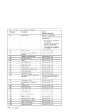
...only, that any of the following conditions: A four-digit code in the range of the FRUs listed in the range E010 to E0FF. Starting SP. A four-digit code displays in the checkpoint table, but is not listed in the checkpoint table. I /O board. (See notes on page 3-32. ... note on 3-1.) NA Service Processor. 1. I /O board. (See notes on 3-29. 1. These checkpoints are not intended to checkpoints. self-tests E011 E012 E020 SP self-tests completed successfully Begin to FRU Index 3-29 This is included with respect to be taken with each checkpoint.
...only, that any of the following conditions: A four-digit code in the range of the FRUs listed in the range E010 to E0FF. Starting SP. A four-digit code displays in the checkpoint table, but is not listed in the checkpoint table. I /O board. (See notes on page 3-32. ... note on 3-1.) NA Service Processor. 1. I /O board. (See notes on 3-29. 1. These checkpoints are not intended to checkpoints. self-tests E011 E012 E020 SP self-tests completed successfully Begin to FRU Index 3-29 This is included with respect to be taken with each checkpoint.

Service Guide
Page 102
.... 2. Service Processor. 2. Service Processor. 3. Table 3-4 (Page 2 of 3). I /O board. (See notes on 3-1.) 3. CPU Card. 1. CPU Card. 1. CPU Card. 3-30 Service Guide Service Processor. 2. CPU Card. 1. Modem. 2. SP Checkpoints. Service Processor. 2. Service Processor. 2. I /O board. (See notes on 3-1.) 1. CPU Card. 1. I /O board. (See notes on (Timer) E070 Configuring modem Action/ Possible Failing FRU 1. CPU Card...
.... 2. Service Processor. 2. Service Processor. 3. Table 3-4 (Page 2 of 3). I /O board. (See notes on 3-1.) 3. CPU Card. 1. CPU Card. 1. CPU Card. 3-30 Service Guide Service Processor. 2. CPU Card. 1. Modem. 2. SP Checkpoints. Service Processor. 2. Service Processor. 2. I /O board. (See notes on 3-1.) 1. CPU Card. 1. I /O board. (See notes on (Timer) E070 Configuring modem Action/ Possible Failing FRU 1. CPU Card...

Service Guide
Page 103
... Chapter 3. Service Processor. 2. Service Processor. 1. Service Processor. Error Code to call home E075 E076 E0A0 E0B0 E0C0 E0E0 E0E1 Entering SP menus Leaving SP menus; Action/ Possible Failing FRU 1. Modem. 2. CPU Card. 1. I /O board. (See notes on . CPU Card. 2. See...Up Phase Starting CPU BIST Starting X5 BIST Pulling CPU out of reset Pull CPU out of 3). System board. (See notes on 3-1.) 3. Normal operation. SP Checkpoints. Service Processor. 3. CPU Card. 1. None. System was shutdown by a privileged system user with no faults. I /O board. (See notes on...
... Chapter 3. Service Processor. 2. Service Processor. 1. Service Processor. Error Code to call home E075 E076 E0A0 E0B0 E0C0 E0E0 E0E1 Entering SP menus Leaving SP menus; Action/ Possible Failing FRU 1. Modem. 2. CPU Card. 1. I /O board. (See notes on . CPU Card. 2. See...Up Phase Starting CPU BIST Starting X5 BIST Pulling CPU out of reset Pull CPU out of 3). System board. (See notes on 3-1.) 3. Normal operation. SP Checkpoints. Service Processor. 3. CPU Card. 1. None. System was shutdown by a privileged system user with no faults. I /O board. (See notes on...

Service Guide
Page 104
... - See the note on 3-29. These checkpoints occur during system startup and maybe be useful in diagnosing certain problems. Service Processor checkpoints are listed in "SP Checkpoints" on 3-29. Firmware Checkpoints. turn on cache Action/ Possible Failing FRU See the note on page 3-29. See the note on 3-29. See the...
... - See the note on 3-29. These checkpoints occur during system startup and maybe be useful in diagnosing certain problems. Service Processor checkpoints are listed in "SP Checkpoints" on 3-29. Firmware Checkpoints. turn on cache Action/ Possible Failing FRU See the note on page 3-29. See the note on 3-29. See the...

Service Guide
Page 107
...) Probe primary 64 bit PCI bus Create host PCI controller node Create MPIC node Adapter VPD probe CPU node VPD creation Root node VPD creation SP node VPD creation Create PCI graphics node (P9) Create PCI graphics node (S3) GTX100P Subsystem Open request. PCI Adapters 2. Table 3-5 (Page 4 of PCI Bus Probe...
...) Probe primary 64 bit PCI bus Create host PCI controller node Create MPIC node Adapter VPD probe CPU node VPD creation Root node VPD creation SP node VPD creation Create PCI graphics node (P9) Create PCI graphics node (S3) GTX100P Subsystem Open request. PCI Adapters 2. Table 3-5 (Page 4 of PCI Bus Probe...
Service Guide
Page 108
...) creation and initialization. Create op-panel node. 3-36 Service Guide Action/ Possible Failing FRU Refer to TFTP error condition Create PCI token ring node SP Command setup SP Post Create ISA node Initialize Super I/O. See the note on 3-29. See the note on 3-29. See the note on 3-29. Create tablet node...
...) creation and initialization. Create op-panel node. 3-36 Service Guide Action/ Possible Failing FRU Refer to TFTP error condition Create PCI token ring node SP Command setup SP Post Create ISA node Initialize Super I/O. See the note on 3-29. See the note on 3-29. See the note on 3-29. Create tablet node...

Service Guide
Page 303
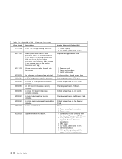
... failure Critical EPOW reporting Checkstop Machine check Call In Power-on via ring-indicate Password/security check Console mirroring/Quick disconnect Thermal/Voltage/fan speed SP Flash Update(Recovery and Composite) Appendix B. Service Processor Menus B-25
... failure Critical EPOW reporting Checkstop Machine check Call In Power-on via ring-indicate Password/security check Console mirroring/Quick disconnect Thermal/Voltage/fan speed SP Flash Update(Recovery and Composite) Appendix B. Service Processor Menus B-25

Service Guide
Page 304
... do not affect its accuracy. Timed power-on at the time AC loss occurred. If Unattended Start Mode is enabled, the server will power on - SP Menu power-on request You can request a power-on Switch - If the system was powered-on your server powers on disables remote call is restored...
... do not affect its accuracy. Timed power-on at the time AC loss occurred. If Unattended Start Mode is enabled, the server will power on - SP Menu power-on request You can request a power-on Switch - If the system was powered-on your server powers on disables remote call is restored...

Service Guide
Page 305
...automatic restart policy (see operating system documentation) indicates the OS response to reboot/restart after a system failure, the Service Processor (SP) monitors the boot progress (via surveillance). If the operating system is Yes (the default), the Service Processor takes over for ... Set Surveillance Parameters). Failure During Boot Process: During the boot process, either initially after the system hardware reinitialized. The SP can monitor operating system activity (see OS documentation). Service Processor Menus B-27 If progress stops, the Service Processor can ...
...automatic restart policy (see operating system documentation) indicates the OS response to reboot/restart after a system failure, the Service Processor (SP) monitors the boot progress (via surveillance). If the operating system is Yes (the default), the Service Processor takes over for ... Set Surveillance Parameters). Failure During Boot Process: During the boot process, either initially after the system hardware reinitialized. The SP can monitor operating system activity (see OS documentation). Service Processor Menus B-27 If progress stops, the Service Processor can ...

Service Guide
Page 306
... restart policy for its action. Refer to use OS-Defined restart policy? No No Yes Yes No No Yes Yes No No Yes Yes SP Enable supplemental restart policy? The following provides a more thorough understanding of the relations among the OS and Service Processor restart controls: OS Automatic ...reboot/restart after crash setting None None None None False False False False True True True True SP to "Service Processor Reboot/Restart Recovery" on page B-27. If set to YES and the operating system has NO automatic restart policy. The...
... restart policy for its action. Refer to use OS-Defined restart policy? No No Yes Yes No No Yes Yes No No Yes Yes SP Enable supplemental restart policy? The following provides a more thorough understanding of the relations among the OS and Service Processor restart controls: OS Automatic ...reboot/restart after crash setting None None None None False False False False True True True True SP to "Service Processor Reboot/Restart Recovery" on page B-27. If set to YES and the operating system has NO automatic restart policy. The...

Service Guide
Page 319
.... With the following names: Diskette File Name modem_z.cfg modem_z0.cfg modem_f.cfg modem_f0.cfg modem_f1.cfg Service Processor Firmware File Name modem_z.sp modem_z0.sp modem_f.sp modem_f0.sp modem_f1.sp The sample modem configuration files can be suitable for your modem, or provide a good starting point for use with your use. Modem Configurations...
.... With the following names: Diskette File Name modem_z.cfg modem_z0.cfg modem_f.cfg modem_f0.cfg modem_f1.cfg Service Processor Firmware File Name modem_z.sp modem_z0.sp modem_f.sp modem_f0.sp modem_f1.sp The sample modem configuration files can be suitable for your modem, or provide a good starting point for use with your use. Modem Configurations...

Service Guide
Page 341
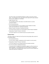
...Appendix E. Service Processor Operational Phases This section provides a high-level flow of the phases of the Service Processor (SP). SP Power Applied │ Pre-Standby Phase │ │ │ │ Standby Phase SP Menus Available │ │ │ │ Bring-Up Phase SMS Menus Available │ │...9474; │ Pre-Standby Phase This phase is entered when the server is set, the SP automatically reboots the server. SP POST SP conducts Power-On Self Tests on . SP will not wait for a user-input or power-on command, but will move straight through the...
...Appendix E. Service Processor Operational Phases This section provides a high-level flow of the phases of the Service Processor (SP). SP Power Applied │ Pre-Standby Phase │ │ │ │ Standby Phase SP Menus Available │ │ │ │ Bring-Up Phase SMS Menus Available │ │...9474; │ Pre-Standby Phase This phase is entered when the server is set, the SP automatically reboots the server. SP POST SP conducts Power-On Self Tests on . SP will not wait for a user-input or power-on command, but will move straight through the...

Service Guide
Page 342
... the server ON after an operating system fault, recognized by OK in two ways: 1. The Standby phase components are : Retry Request Check The SP will configure the modem (if installed) so that incoming calls may be received, or outgoing calls may be reached in the LCD display. 2. The... Bring-up phase components are : Modem Configuration SP will check to answer calls, prompt for menus operation. If two consecutive fails are password protected. Dial Out E-2 Service Guide Bring-Up Phase This...
... the server ON after an operating system fault, recognized by OK in two ways: 1. The Standby phase components are : Retry Request Check The SP will configure the modem (if installed) so that incoming calls may be received, or outgoing calls may be reached in the LCD display. 2. The... Bring-up phase components are : Modem Configuration SP will check to answer calls, prompt for menus operation. If two consecutive fails are password protected. Dial Out E-2 Service Guide Bring-Up Phase This...
Service Guide
Page 343
...on the ASCII terminal if a remote connection is installed and surveillance enabled, the SP will monitor and time the interval between system firmware heartbeats. This is now controlled by the SP instead of the base system, with the last reported IPL status indicated and ... pre-programmed telephone number in the event of the operating system. System Firmware Surveillance (Heartbeat Monitoring) The SP will monitor the system heartbeat. The SP issues an error report with expanded error recording and reporting. Environmental Monitoring Environmental Monitoring is different from the ...
...on the ASCII terminal if a remote connection is installed and surveillance enabled, the SP will monitor and time the interval between system firmware heartbeats. This is now controlled by the SP instead of the base system, with the last reported IPL status indicated and ... pre-programmed telephone number in the event of the operating system. System Firmware Surveillance (Heartbeat Monitoring) The SP will monitor the system heartbeat. The SP issues an error report with expanded error recording and reporting. Environmental Monitoring Environmental Monitoring is different from the ...

Service Guide
Page 349
messages, SP checkpoints 3-29 microcode maintenance 3-92 software errors A-5 minimum configuration Map 2-17 missing disk drive module 3-75 mode, set service 3-67 modem configuration file selection D-2... table A-5 network information, SSA 3-76 numbers, service request description of A-3 software and microcode errors A-5 table A-6 NVRAM B-14 O OK 2-1, 3-31, E-2 online diagnostics 4-1 operational phases, SP standby E-2 operator panel 1-7 operator panel control assembly operator panel control assembly 6-45 removal and replacement 6-45 operator panel display removal and replacement 6-44 P pager B-18...
messages, SP checkpoints 3-29 microcode maintenance 3-92 software errors A-5 minimum configuration Map 2-17 missing disk drive module 3-75 mode, set service 3-67 modem configuration file selection D-2... table A-5 network information, SSA 3-76 numbers, service request description of A-3 software and microcode errors A-5 table A-6 NVRAM B-14 O OK 2-1, 3-31, E-2 online diagnostics 4-1 operational phases, SP standby E-2 operator panel 1-7 operator panel control assembly operator panel control assembly 6-45 removal and replacement 6-45 operator panel display removal and replacement 6-44 P pager B-18...