

Hardware Maintenance Manual
Page 15
BladeCenter T Type 8720 features and specifications Media tray (on front): v DVD/CD-RW drive: slim IDE v Two Universal Serial Bus (USB) v2.0 full speed ports v System-status panel Module bays (on front): v Eight hot-swap blade bays v Four hot-swap power-module bays v Two hot-swap management module bays Module bays (on : 5° to 40°C (41° to 104°F) - All four blower modules - I /O modules: v Standard: None...
BladeCenter T Type 8720 features and specifications Media tray (on front): v DVD/CD-RW drive: slim IDE v Two Universal Serial Bus (USB) v2.0 full speed ports v System-status panel Module bays (on front): v Eight hot-swap blade bays v Four hot-swap power-module bays v Two hot-swap management module bays Module bays (on : 5° to 40°C (41° to 104°F) - All four blower modules - I /O modules: v Standard: None...
Hardware Maintenance Manual
Page 41
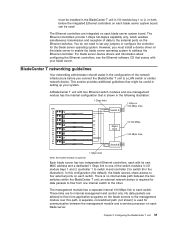
...; an external network device is optional Each blade server has two independent Ethernet controllers, each blade server system board can be useful in the illustration). Configuring the BladeCenter T unit 31 However, you must be installed in the BladeCenter T unit in I /O module bays 1 and 2 (controller 1 to switch A and controller 2 to switch B in setting up your blade server. BladeCenter T networking guidelines Your networking administrator should assist...
...; an external network device is optional Each blade server has two independent Ethernet controllers, each blade server system board can be useful in the illustration). Configuring the BladeCenter T unit 31 However, you must be installed in the BladeCenter T unit in I /O module bays 1 and 2 (controller 1 to switch A and controller 2 to switch B in setting up your blade server. BladeCenter T networking guidelines Your networking administrator should assist...
Hardware Maintenance Manual
Page 52
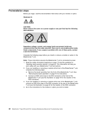
... to install. 42 BladeCenter T Type 8720 and 8730: Hardware Maintenance Manual and Troubleshooting Guide Note: These instructions assume the BladeCenter T unit is connected to the instructions for the location of these components. Read the safety information beginning on a power supply or any component that has this label attached. If you are present inside these parts, contact a service technician. b. Statement 8: CAUTION: Never remove the...
... to install. 42 BladeCenter T Type 8720 and 8730: Hardware Maintenance Manual and Troubleshooting Guide Note: These instructions assume the BladeCenter T unit is connected to the instructions for the location of these components. Read the safety information beginning on a power supply or any component that has this label attached. If you are present inside these parts, contact a service technician. b. Statement 8: CAUTION: Never remove the...
Hardware Maintenance Manual
Page 61
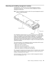
... console for viewing. Use the instructions in management-module bay 2. Setting up the BladeCenter T hardware 51 The management module configures the BladeCenter T unit and modules, configuring information such as a service processor for information about the controls and indicators. The management module also performs USB-to detect presence or absence and any error conditions, sending alerts when required. Removing and installing management modules The BladeCenter T unit comes with one...
... console for viewing. Use the instructions in management-module bay 2. Setting up the BladeCenter T hardware 51 The management module configures the BladeCenter T unit and modules, configuring information such as a service processor for information about the controls and indicators. The management module also performs USB-to detect presence or absence and any error conditions, sending alerts when required. Removing and installing management modules The BladeCenter T unit comes with one...

Hardware Maintenance Manual
Page 64
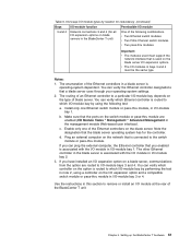
... power module has cooling fans that are installed with the release lever facing downward. 54 BladeCenter T Type 8720 and 8730: Hardware Maintenance Manual and Troubleshooting Guide Note: Blowers on the left side of the system are installed with four hot-swap blowers for cooling redundancy. If a blower fails, the remaining blowers increase their speed to restore cooling redundancy. Error LED Power LED Blower...
... power module has cooling fans that are installed with the release lever facing downward. 54 BladeCenter T Type 8720 and 8730: Hardware Maintenance Manual and Troubleshooting Guide Note: Blowers on the left side of the system are installed with four hot-swap blowers for cooling redundancy. If a blower fails, the remaining blowers increase their speed to restore cooling redundancy. Error LED Power LED Blower...

Hardware Maintenance Manual
Page 66
... the electrical and mechanical interface to install or remove the KVM module. Removing and installing the KVM (keyboard, video, mouse) module The KVM module is a hot-swap unit that you do not overtighten the thumbscrews. 4 2 3 1 LAN module KVM module 56 BladeCenter T Type 8720 and 8730: Hardware Maintenance Manual and Troubleshooting Guide Five LEDs on page 16 for system status information: power, location, minor alarm, major alarm...
... the electrical and mechanical interface to install or remove the KVM module. Removing and installing the KVM (keyboard, video, mouse) module The KVM module is a hot-swap unit that you do not overtighten the thumbscrews. 4 2 3 1 LAN module KVM module 56 BladeCenter T Type 8720 and 8730: Hardware Maintenance Manual and Troubleshooting Guide Five LEDs on page 16 for system status information: power, location, minor alarm, major alarm...
Hardware Maintenance Manual
Page 71
... combinations. The other Ethernet controller in the blade server is routed to remove or install an I /O-module bay by performing the test in the BladeCenter T unit) One of the following test: a. Use the instructions in the management module Web-based user interface). Notes: 1. Enable only one Ethernet switch module or pass-thru module, in I /O Module Tasks " Management " Advanced Management in this section to...
... combinations. The other Ethernet controller in the blade server is routed to remove or install an I /O-module bay by performing the test in the BladeCenter T unit) One of the following test: a. Use the instructions in the management module Web-based user interface). Notes: 1. Enable only one Ethernet switch module or pass-thru module, in I /O Module Tasks " Management " Advanced Management in this section to...
Hardware Maintenance Manual
Page 74
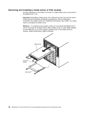
... bay number. Removing and installing a blade server or filler module Use the instructions in each blade bay. Attention: To maintain proper system cooling, do not operate the BladeCenter T unit for more than the one from which it was removed could have unintended consequences. CMM 1 Blade Server CMM 2 ESD Release latches Filler blade 64 BladeCenter T Type 8720 and 8730: Hardware Maintenance Manual and Troubleshooting Guide...
... bay number. Removing and installing a blade server or filler module Use the instructions in each blade bay. Attention: To maintain proper system cooling, do not operate the BladeCenter T unit for more than the one from which it was removed could have unintended consequences. CMM 1 Blade Server CMM 2 ESD Release latches Filler blade 64 BladeCenter T Type 8720 and 8730: Hardware Maintenance Manual and Troubleshooting Guide...
Hardware Maintenance Manual
Page 99
.... Note: Try reseating a suspected component or reconnecting a cable before you just added. 2. Symptom-to -FRU index lists symptoms, errors, and the possible causes. For IBM devices not supported by this symptom-to-FRU index to see if the problem has been corrected before using the troubleshooting charts: 1. The left-hand column of firmware code installed. Check the configuration before replacing the component.
.... Note: Try reseating a suspected component or reconnecting a cable before you just added. 2. Symptom-to -FRU index lists symptoms, errors, and the possible causes. For IBM devices not supported by this symptom-to-FRU index to see if the problem has been corrected before using the troubleshooting charts: 1. The left-hand column of firmware code installed. Check the configuration before replacing the component.
Hardware Maintenance Manual
Page 100
.... 3. Do not switch KVM control between blade servers gives USB device error. Some components do not have these items installed or have them . Blade bays that currently owns the media tray, as the amber blade error LED on , the amber system-error replacing a failed microprocessor in them installed improperly disturb airflow in the BladeCenter T unit with the lowest feature set and stepping level...
.... 3. Do not switch KVM control between blade servers gives USB device error. Some components do not have these items installed or have them . Blade bays that currently owns the media tray, as the amber blade error LED on , the amber system-error replacing a failed microprocessor in them installed improperly disturb airflow in the BladeCenter T unit with the lowest feature set and stepping level...
Hardware Maintenance Manual
Page 102
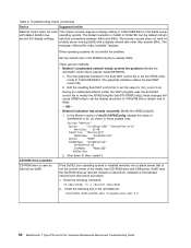
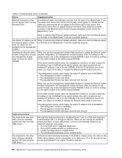
...installed remotely onto a blade server that is not the current owner of the media tray (CD-ROM drive and USB ports), SuSE sees the CD-ROM drive.../No video available" displays. v Method 1 (unattended network install, prevent the problem): Modify...set the VESA video mode to 60. Troubleshooting charts (continued) Device Suggested action Remote control does not work for min_vsync to 1040x768@60Hz. Set the refresh rate in the /etc/fstab file: /dev/cdrom /media/cdrom auto ro,noauto,user,exec 0 0 92 BladeCenter T Type 8720 and 8730: Hardware Maintenance Manual and Troubleshooting Guide...
...installed remotely onto a blade server that is not the current owner of the media tray (CD-ROM drive and USB ports), SuSE sees the CD-ROM drive.../No video available" displays. v Method 1 (unattended network install, prevent the problem): Modify...set the VESA video mode to 60. Troubleshooting charts (continued) Device Suggested action Remote control does not work for min_vsync to 1040x768@60Hz. Set the refresh rate in the /etc/fstab file: /dev/cdrom /media/cdrom auto ro,noauto,user,exec 0 0 92 BladeCenter T Type 8720 and 8730: Hardware Maintenance Manual and Troubleshooting Guide...
Hardware Maintenance Manual
Page 104
... problems The keyboard is accidentally removed from the back of the BladeCenter T unit, the small red X (disconnect notice) that normally would appear to the switch-module NVRAM. Run the blade server integrated diagnostics 2. Troubleshooting charts (continued) Device Suggested action Ethernet disconnect notice will use the management-module Web interface to update the Ethernet switch module configuration, the management module firmware writes its settings for the switch module...
... problems The keyboard is accidentally removed from the back of the BladeCenter T unit, the small red X (disconnect notice) that normally would appear to the switch-module NVRAM. Run the blade server integrated diagnostics 2. Troubleshooting charts (continued) Device Suggested action Ethernet disconnect notice will use the management-module Web interface to update the Ethernet switch module configuration, the management module firmware writes its settings for the switch module...

Hardware Maintenance Manual
Page 105
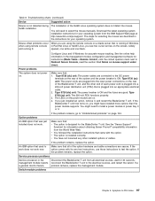
Remote console has keyboard entry problems with the Windows XP Service Pack 1. for (requires restart)' Management-module problems The management module password cannot be overridden, and the management module will not be replaced. See the IBM 4-Port Gb Ethernet Switch Module for BladeCenter T Installation Guide for instructions on the BladeCenter T unit can obtain the Microsoft JVM for the F1 key. This problem is lost temporarily. The Microsoft JVM comes...
Remote console has keyboard entry problems with the Windows XP Service Pack 1. for (requires restart)' Management-module problems The management module password cannot be overridden, and the management module will not be replaced. See the IBM 4-Port Gb Ethernet Switch Module for BladeCenter T Installation Guide for instructions on the BladeCenter T unit can obtain the Microsoft JVM for the F1 key. This problem is lost temporarily. The Microsoft JVM comes...
Hardware Maintenance Manual
Page 107
... problem remains, replace the option. Configure Linux and X Windows for your operating system. Make sure that was just installed does not work now. If the problem remains, replace the option. spaced, one white and one black. Option problems An IBM option that : v The option is installed correctly. If a a general monitor failure. The LEDs on the power module are described in the instructions for the BladeCenter...
... problem remains, replace the option. Configure Linux and X Windows for your operating system. Make sure that was just installed does not work now. If the problem remains, replace the option. spaced, one white and one black. Option problems An IBM option that : v The option is installed correctly. If a a general monitor failure. The LEDs on the power module are described in the instructions for the BladeCenter...
Hardware Maintenance Manual
Page 114
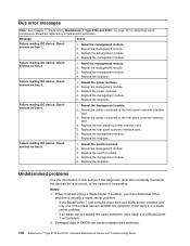
... management module. 7. Reseat the switch modules. 2. Replace the switch modules. 4. Replace the midplane. v If the BladeCenter T unit contains more then one blade server installed and only one of the blade servers exhibits the symptom, most likely it is actually a blade server problem. Reset the management module. 2. Reseat the power modules. 2. Reseat the management module. 3. Replace the power modules. 4. Reseat the cables connected to the front panel customer interface card. 3. Replace the midplane. When troubleshooting a BladeCenter T problem...
... management module. 7. Reseat the switch modules. 2. Replace the switch modules. 4. Replace the midplane. v If the BladeCenter T unit contains more then one blade server installed and only one of the blade servers exhibits the symptom, most likely it is actually a blade server problem. Reset the management module. 2. Reseat the power modules. 2. Reseat the management module. 3. Replace the power modules. 4. Reseat the cables connected to the front panel customer interface card. 3. Replace the midplane. When troubleshooting a BladeCenter T problem...
Installation Guide
Page 39
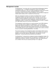
...-ROM drive and USB port) The BladeCenter T components are installed in management-module bay 2. This helps ensure a smooth changeover of management-module firmware is switched to the redundant management module. The latest level of control from the active management module to act as primary. The management module functions as a service processor and a KVM multiplexor for all components in management bay 1. When two management modules are configured...
...-ROM drive and USB port) The BladeCenter T components are installed in management-module bay 2. This helps ensure a smooth changeover of management-module firmware is switched to the redundant management module. The latest level of control from the active management module to act as primary. The management module functions as a service processor and a KVM multiplexor for all components in management bay 1. When two management modules are configured...

Installation Guide
Page 64
... on IBM BladeCenter v Deploying Citrix MetalFrame on each blade server system board. Application considerations Information about your option for information about installing any jumpers or configure the controller for the blade server operating system. The Ethernet controllers provide 1000-Mbps full-duplex capability only, which enables simultaneous transmission and reception of data to set any required device drivers. However...
... on IBM BladeCenter v Deploying Citrix MetalFrame on each blade server system board. Application considerations Information about your option for information about installing any jumpers or configure the controller for the blade server operating system. The Ethernet controllers provide 1000-Mbps full-duplex capability only, which enables simultaneous transmission and reception of data to set any required device drivers. However...

Installation Guide
Page 91
... the secure socket layer (SSL) settings for the Ethernet switch module include: v Switch settings v Port settings v SNMP Chapter 5. If you choose to enable SSL, you can determine whether to back up or restore the management-module configuration file. Configuration file Configuration File is used to update the management-module firmware; Configuration considerations 77 Options that you can configure for the Web server and LDAP client v View...
... the secure socket layer (SSL) settings for the Ethernet switch module include: v Switch settings v Port settings v SNMP Chapter 5. If you choose to enable SSL, you can determine whether to back up or restore the management-module configuration file. Configuration file Configuration File is used to update the management-module firmware; Configuration considerations 77 Options that you can configure for the Web server and LDAP client v View...
Installation Guide
Page 94
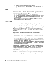
... access to all switch settings, plus the ability to be configured. The BladeCenter T unit default VLAN ID is uploaded to a TFTP server to restart the switch module. Review the following points: v Blade server ports that interconnects the BladeCenter T units must be untagged. 80 BladeCenter T Types 8720 and 8730: Planning and Installation Guide VLAN traffic can extend across multiple BladeCenter T units, intermediate switches use the VLAN...
... access to all switch settings, plus the ability to be configured. The BladeCenter T unit default VLAN ID is uploaded to a TFTP server to restart the switch module. Review the following points: v Blade server ports that interconnects the BladeCenter T units must be untagged. 80 BladeCenter T Types 8720 and 8730: Planning and Installation Guide VLAN traffic can extend across multiple BladeCenter T units, intermediate switches use the VLAN...
Installation Guide
Page 100
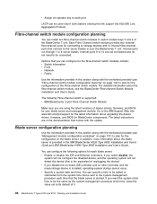
... switch module bays 3 and 4 of device drivers, firmware, and BIOS for the configuration of the blade server. If you want the system clock time to be connected. You can be added or subtracted from the system time that is sent to the system-management processor each time that comes with the worksheet provided (see the BladeCenter Fibre-channel Switch Module Installation and User's Guide...
... switch module bays 3 and 4 of device drivers, firmware, and BIOS for the configuration of the blade server. If you want the system clock time to be connected. You can be added or subtracted from the system time that is sent to the system-management processor each time that comes with the worksheet provided (see the BladeCenter Fibre-channel Switch Module Installation and User's Guide...