
Hardware Maintenance Manual
Page 5
... 8196 and 8197 37 Identifying parts on the system board (all machine types 38 Replacing memory (all machine types) . . . . . 38 Replacing adapters 39 Types 8185, 8186, 8192, 8413, and 8430 . . . . 39 Types 8128, 8187, 8188, 8193, 8414, and 8431 . . 41 Types 8189, 8190, 8194, 8195...P6 110 Connector P8 (Serial ATA 110 Chapter 8. Additional Service Information 111 iii IBM Setup Utility program 19 Starting the IBM Setup Utility program . . . . . 19 Viewing and changing settings 19 Exiting from the IBM Setup Utility program . . . 20 Using passwords 20 User password 20 Administrator ...
... 8196 and 8197 37 Identifying parts on the system board (all machine types 38 Replacing memory (all machine types) . . . . . 38 Replacing adapters 39 Types 8185, 8186, 8192, 8413, and 8430 . . . . 39 Types 8128, 8187, 8188, 8193, 8414, and 8431 . . 41 Types 8189, 8190, 8194, 8195...P6 110 Connector P8 (Serial ATA 110 Chapter 8. Additional Service Information 111 iii IBM Setup Utility program 19 Starting the IBM Setup Utility program . . . . . 19 Viewing and changing settings 19 Exiting from the IBM Setup Utility program . . . 20 Using passwords 20 User password 20 Administrator ...
Hardware Maintenance Manual
Page 9
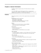
...some models) v Internal cache (size varies by model type) Memory v Support for four dual inline memory modules (DIMMs) v 512 KB flash memory for system programs Internal drives v 3.5-inch, 1.44 MB diskette drive v Internal hard disk drive v EIDE CD-ROM drive... or DVD-ROM drive (some models) Video subsystem v An integrated graphics controller for general information about the use, operation, and maintenance of the computer features and preinstalled software. Access IBM...
...some models) v Internal cache (size varies by model type) Memory v Support for four dual inline memory modules (DIMMs) v 512 KB flash memory for system programs Internal drives v 3.5-inch, 1.44 MB diskette drive v Internal hard disk drive v EIDE CD-ROM drive... or DVD-ROM drive (some models) Video subsystem v An integrated graphics controller for general information about the use, operation, and maintenance of the computer features and preinstalled software. Access IBM...
Hardware Maintenance Manual
Page 17
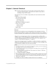
... v Product recovery utility - See Chapter 4, "IBM Enhanced Diagnostics," on how to the information supplied with that the latest level of the system board. Notes: v By default, the computer starts up quiet (no beep and no memory count and checkpoint code display) when no errors are... displayed, diagnose the first error code displayed. © Copyright IBM Corp. 2005 11 v Before replacing any FRUs, ensure that software package. The following :...
... v Product recovery utility - See Chapter 4, "IBM Enhanced Diagnostics," on how to the information supplied with that the latest level of the system board. Notes: v By default, the computer starts up quiet (no beep and no memory count and checkpoint code display) when no errors are... displayed, diagnose the first error code displayed. © Copyright IBM Corp. 2005 11 v Before replacing any FRUs, ensure that software package. The following :...

Hardware Maintenance Manual
Page 25
... any similar settings in the electrically erasable programmable read-only memory (EEPROM) of each screen. © Copyright IBM Corp. 2005 19 This program includes settings for a few seconds until all in the computer. IBM Setup Utility program Attention A customized setup configuration (other than...removed or new hardware has been installed in -use the keyboard. Follow the instructions on the computer. 3. The IBM Setup Utility might exist on the screen during start the IBM Setup Utility program, do the following : v System Summary v Product Data v Devices and I/O Ports v ...
... any similar settings in the electrically erasable programmable read-only memory (EEPROM) of each screen. © Copyright IBM Corp. 2005 19 This program includes settings for a few seconds until all in the computer. IBM Setup Utility program Attention A customized setup configuration (other than...removed or new hardware has been installed in -use the keyboard. Follow the instructions on the computer. 3. The IBM Setup Utility might exist on the screen during start the IBM Setup Utility program, do the following : v System Summary v Product Data v Devices and I/O Ports v ...

Hardware Maintenance Manual
Page 40
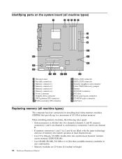
Locating components Types 8185, 8186, 8192, 8413, and 8430 The following illustration will help you locate the various components in the computer. 1 Power supply 2 PCI adapter connector 3 AGP adapter connector 4 Support bar 5 Memory connector 6 Hard disk drive 7 Optical drive 8 Diskette drive 34 Hardware Maintenance Manual
Locating components Types 8185, 8186, 8192, 8413, and 8430 The following illustration will help you locate the various components in the computer. 1 Power supply 2 PCI adapter connector 3 AGP adapter connector 4 Support bar 5 Memory connector 6 Hard disk drive 7 Optical drive 8 Diskette drive 34 Hardware Maintenance Manual

Hardware Maintenance Manual
Page 41
Replacing FRUs 35 Types 8128, 8187, 8188, 8193, 8414, and 8431 The following illustration will help you locate the various components in the computer. 1 Optical drive 2 USB connector 3 USB connector 4 Optional drive bay 5 Hard disk drive 6 Diskette drive 7 Memory connectors 8 Microprocessor and heat sink 9 AGP adapter connector 10 Battery 11 PCI adapter connectors Chapter 6.
Replacing FRUs 35 Types 8128, 8187, 8188, 8193, 8414, and 8431 The following illustration will help you locate the various components in the computer. 1 Optical drive 2 USB connector 3 USB connector 4 Optional drive bay 5 Hard disk drive 6 Diskette drive 7 Memory connectors 8 Microprocessor and heat sink 9 AGP adapter connector 10 Battery 11 PCI adapter connectors Chapter 6.

Hardware Maintenance Manual
Page 42
Types 8189, 8190, 8194, 8195, 8415, 8432, and 8433 The following illustration will help you locate the various components in the computer. 1 Microprocessor and heat sink 2 Memory connectors 3 AGP adapter connector 4 PCI adapter 5 Power supply 36 Hardware Maintenance Manual
Types 8189, 8190, 8194, 8195, 8415, 8432, and 8433 The following illustration will help you locate the various components in the computer. 1 Microprocessor and heat sink 2 Memory connectors 3 AGP adapter connector 4 PCI adapter 5 Power supply 36 Hardware Maintenance Manual

Hardware Maintenance Manual
Page 43
Replacing FRUs 37 Types 8196 and 8197 The following illustration will help you locate the various components in the computer. 1 Microprocessor and heat sink 2 Memory connectors 3 AGP adapter connector 4 PCI adapter connectors 5 PCI adapter 6 Power supply Chapter 6.
Replacing FRUs 37 Types 8196 and 8197 The following illustration will help you locate the various components in the computer. 1 Microprocessor and heat sink 2 Memory connectors 3 AGP adapter connector 4 PCI adapter connectors 5 PCI adapter 6 Power supply Chapter 6.
Hardware Maintenance Manual
Page 44
... into two channels (channel A and B). v Use 2.5 V, 184-pin, 333 MHz double data rate synchronous dynamic random access memory (DDR SDRAM). v Use 128 MB, 256 MB, 512 MB or 1.0 GB (when available) memory modules in height. 38 Hardware Maintenance Manual v Memory modules are 25.4 mm (1.0 inches) in any combination. Identifying parts on the system board (all machine types...
... into two channels (channel A and B). v Use 2.5 V, 184-pin, 333 MHz double data rate synchronous dynamic random access memory (DDR SDRAM). v Use 128 MB, 256 MB, 512 MB or 1.0 GB (when available) memory modules in height. 38 Hardware Maintenance Manual v Memory modules are 25.4 mm (1.0 inches) in any combination. Identifying parts on the system board (all machine types...

Hardware Maintenance Manual
Page 45
... types)" on page 30. 2. Adapters must be used for PCI adapters and one slot used . Remove the memory module being replaced by opening the retaining clips as shown. 4. Chapter 6. To replace a memory module: 1. Go to 168 mm (6.6 inches) long. 1. See "Removing the cover" on page 63. Push... straight down into the connector until the retaining clips close. 5. Remove the cover. To locate the memory connectors. Make sure the notches in the new memory module align with the tabs on the connector. Replacing adapters Types 8185, 8186, 8192, 8413, and 8430 These type ...
... types)" on page 30. 2. Adapters must be used for PCI adapters and one slot used . Remove the memory module being replaced by opening the retaining clips as shown. 4. Chapter 6. To replace a memory module: 1. Go to 168 mm (6.6 inches) long. 1. See "Removing the cover" on page 63. Push... straight down into the connector until the retaining clips close. 5. Remove the cover. To locate the memory connectors. Make sure the notches in the new memory module align with the tabs on the connector. Replacing adapters Types 8185, 8186, 8192, 8413, and 8430 These type ...

Hardware Maintenance Manual
Page 62
...Refer to the drive. 4. See "Replacing adapters" on the computer. Go to set the date and time and any passwords. 3. Use the IBM Setup Utility program to "Replacing the cover and connecting the cables" on page 63. Replace any adapters that maintains the date, time, and settings ...for information about replacing and disposing of memory that impede access to the battery. Install the new battery. 7. See "Replacing the cover and connecting the cables" on page 63. Turn...
...Refer to the drive. 4. See "Replacing adapters" on the computer. Go to set the date and time and any passwords. 3. Use the IBM Setup Utility program to "Replacing the cover and connecting the cables" on page 63. Replace any adapters that maintains the date, time, and settings ...for information about replacing and disposing of memory that impede access to the battery. Install the new battery. 7. See "Replacing the cover and connecting the cables" on page 63. Turn...

Hardware Maintenance Manual
Page 69
.... 5. Ensure that connect to install any cables that no tools or loose screws are left inside the computer. 2. Refer to "Replacing memory (all components have been reassembled correctly and that might need to the system board. Clear any removed parts, replace the cover, and reconnect..., you need to "Replacing a microprocessor (all machine types)" on the new system board. Refer to confirm the updated information in the IBM Setup Utility program. Chapter 6. Install the microprocessor on page 38. 3. To replace the cover and connect cables to "Replacing the cover ...
.... 5. Ensure that connect to install any cables that no tools or loose screws are left inside the computer. 2. Refer to "Replacing memory (all components have been reassembled correctly and that might need to the system board. Clear any removed parts, replace the cover, and reconnect..., you need to "Replacing a microprocessor (all machine types)" on the new system board. Refer to confirm the updated information in the IBM Setup Utility program. Chapter 6. Install the microprocessor on page 38. 3. To replace the cover and connect cables to "Replacing the cover ...

Hardware Maintenance Manual
Page 76
... machine types)" on page 110. Diagnostic error codes Refer to the following index, X can represent any number. See Chapter 4, "IBM Enhanced Diagnostics," on page 15 for information about the Diagnostic programs. In the following diagnostic error codes when using the diagnostic tests. Flash...on, the power supply fan is not running, or the computer will not power-off, use the following for proper installation. Run Setup 2. Run memory test 4. No action 1. Boot block 3. Flash the system 3. System board 1. Reboot the system 2. Power Cord See "Power supply connectors" on...
... machine types)" on page 110. Diagnostic error codes Refer to the following index, X can represent any number. See Chapter 4, "IBM Enhanced Diagnostics," on page 15 for information about the Diagnostic programs. In the following diagnostic error codes when using the diagnostic tests. Flash...on, the power supply fan is not running, or the computer will not power-off, use the following for proper installation. Run Setup 2. Run memory test 4. No action 1. Boot block 3. Flash the system 3. System board 1. Reboot the system 2. Power Cord See "Power supply connectors" on...

Hardware Maintenance Manual
Page 78
Run memory test 4. Flash the system 2. Power-off /on system and re-test 2. Power-off /on system and re-test 2. System board 1. Press F3 to "Undetermined problems" ...
Run memory test 4. Flash the system 2. Power-off /on system and re-test 2. Power-off /on system and re-test 2. System board 1. Press F3 to "Undetermined problems" ...
Hardware Maintenance Manual
Page 84
No action 1. System board 1. System board System board 1. Run memory test 4. Remove USB device(s) and re-test 2. Remove USB device(s) and re-test 2. Flash the system 2. System board 1. Flash the system 3. Information 2. Re-start the ...
No action 1. System board 1. System board System board 1. Run memory test 4. Remove USB device(s) and re-test 2. Remove USB device(s) and re-test 2. Flash the system 2. System board 1. Flash the system 3. Information 2. Re-start the ...

Hardware Maintenance Manual
Page 92
... Test Passed 185-XXX-XXX Asset Security failure 185-278-XXX Asset Security Chassis Intrusion 201-000-XXX System Memory Test Passed 201-XXX-XXX System Memory error 202-000-XXX System Cache Test Passed 202-XXX-XXX System Cache error FRU/Action No action 1. ...Component under function test 1. Go to reset the log file 1. Check fans 2. Replace the memory module called out in warning statement 4. Check Power supply 3. Microprocessor 4. Microprocessor 86 Hardware Maintenance Manual Re-start the test to "Undetermined problems"...
... Test Passed 185-XXX-XXX Asset Security failure 185-278-XXX Asset Security Chassis Intrusion 201-000-XXX System Memory Test Passed 201-XXX-XXX System Memory error 202-000-XXX System Cache Test Passed 202-XXX-XXX System Cache error FRU/Action No action 1. ...Component under function test 1. Go to reset the log file 1. Check fans 2. Replace the memory module called out in warning statement 4. Check Power supply 3. Microprocessor 4. Microprocessor 86 Hardware Maintenance Manual Re-start the test to "Undetermined problems"...

Hardware Maintenance Manual
Page 95
...Memory module 2. Symptom-to diagnose beep symptoms. Beep Symptom 1-1-3 CMOS read-write error 1-2-2-3 ROM BIOS check error 1-2-1 Programmable Interval Timer failed 1-2-2 DMA Initialization failed 1-2-3 DMA page register write/read failed 1-2-4 RAM refresh verification failed 1-3-3-1 1st 64K RAM test failed 1-3-2 1st 64K RAM...Beep symptoms are short tones or a series of breaks Four continuous beeps Use the following examples. Memory module 2. Run Setup 2. Memory module 2. System Board System Board System Board System Board System Board System Board System Board 1. System Board 1....
...Memory module 2. Symptom-to diagnose beep symptoms. Beep Symptom 1-1-3 CMOS read-write error 1-2-2-3 ROM BIOS check error 1-2-1 Programmable Interval Timer failed 1-2-2 DMA Initialization failed 1-2-3 DMA page register write/read failed 1-2-4 RAM refresh verification failed 1-3-3-1 1st 64K RAM test failed 1-3-2 1st 64K RAM...Beep symptoms are short tones or a series of breaks Four continuous beeps Use the following examples. Memory module 2. Run Setup 2. Memory module 2. System Board System Board System Board System Board System Board System Board System Board 1. System Board 1....

Hardware Maintenance Manual
Page 96
Keyboard Cable 3. System Board 90 Hardware Maintenance Manual System Board 1. System Board System Board System Board System Board System Board System Board 1. Jumper on J28 2. Beep Symptom 2-2-4 CMOS configuration info validation failed 2-3-1 Screen initialization failed 2-3-2 Screen memory failed 2-3-3 Screen retrace failed 1-2 Search for video ROM failed All other beep code sequences Continuous beep Repeating short beeps FRU/Action 1. Keyboard stuck key 2. Battery 2.
Keyboard Cable 3. System Board 90 Hardware Maintenance Manual System Board 1. System Board System Board System Board System Board System Board System Board 1. Jumper on J28 2. Beep Symptom 2-2-4 CMOS configuration info validation failed 2-3-1 Screen initialization failed 2-3-2 Screen memory failed 2-3-3 Screen retrace failed 1-2 Search for video ROM failed All other beep code sequences Continuous beep Repeating short beeps FRU/Action 1. Keyboard stuck key 2. Battery 2.

Hardware Maintenance Manual
Page 97
Any Adapter or Device 5. No beep during POST but computer works correctly. Memory Module 4. Power Supply Chapter 7. Symptom-to-FRU Index 91 FRU/Action System Board 1. Riser Card 6. Power Cord 7. No-beep symptoms Symptom/Error No beep during POST. See "Undetermined problems" on page 109. 2. System Board 3.
Any Adapter or Device 5. No beep during POST but computer works correctly. Memory Module 4. Power Supply Chapter 7. Symptom-to-FRU Index 91 FRU/Action System Board 1. Riser Card 6. Power Cord 7. No-beep symptoms Symptom/Error No beep during POST. See "Undetermined problems" on page 109. 2. System Board 3.

Hardware Maintenance Manual
Page 98
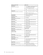
... Adapter not enabled 02X 08X Check SCSI terminator installation. 101 System board interrupt failure 102 System board timer error 106 110 System board memory parity error FRU/Action Verify adapter device and Bus Master fields are detected by POST. SCSI Device 4. If the POST detects a problem...the screen. Set Power-On Self-Test to come up quiet (no beep and no memory count and checkpoint code display) when no errors are enabled in the IBM Setup Utility program (see Chapter 5, "IBM Setup Utility program," on page 19). 2. Memory Module 2. System Board 92 Hardware Maintenance Manual
... Adapter not enabled 02X 08X Check SCSI terminator installation. 101 System board interrupt failure 102 System board timer error 106 110 System board memory parity error FRU/Action Verify adapter device and Bus Master fields are detected by POST. SCSI Device 4. If the POST detects a problem...the screen. Set Power-On Self-Test to come up quiet (no beep and no memory count and checkpoint code display) when no errors are enabled in the IBM Setup Utility program (see Chapter 5, "IBM Setup Utility program," on page 19). 2. Memory Module 2. System Board 92 Hardware Maintenance Manual


