

Maintenance Manual
Page 3
... Safety Inspection ...21 Preparation...21 Prepare The Printer For Inspection ...21 Inspect Mechanical Parts ...22 Inspect Electrical Parts...23 Preface ...26 About This Manual ...26 Printing Conventions In This Manual ...27 Related Documents...28 About The Printer...29 The IBM Infoprint 6500 Printer Family ...29 How To Identify The Printer ...30 Printer Configuration Code...
... Safety Inspection ...21 Preparation...21 Prepare The Printer For Inspection ...21 Inspect Mechanical Parts ...22 Inspect Electrical Parts...23 Preface ...26 About This Manual ...26 Printing Conventions In This Manual ...27 Related Documents...28 About The Printer...29 The IBM Infoprint 6500 Printer Family ...29 How To Identify The Printer ...30 Printer Configuration Code...

Maintenance Manual
Page 7
...Dynamic Paper Tension Adjustment ...384 Tractor Belt Tension Adjustment ...387 Ethernet Initialization...389 6 Parts Catalog ...390 Organization Of This Chapter ...390 Illustrated Parts Breakdown...390 7 Preventive Maintenance 431 Contents ...431 Cleaning The Printer...432 Cleaning The Exterior... And Relocating The Printer 437 Installing And Configuring The Infoprint 6500 Printer ...437 Relocating The Infoprint 6500 Printer ...437 B Communication Adapters 438 Contents ...438 Ethernet Interface Assembly...439 Ethernet Troubleshooting Tips...439 IBM Coax/Twinax Expansion Board ...444 7
...Dynamic Paper Tension Adjustment ...384 Tractor Belt Tension Adjustment ...387 Ethernet Initialization...389 6 Parts Catalog ...390 Organization Of This Chapter ...390 Illustrated Parts Breakdown...390 7 Preventive Maintenance 431 Contents ...431 Cleaning The Printer...432 Cleaning The Exterior... And Relocating The Printer 437 Installing And Configuring The Infoprint 6500 Printer ...437 Relocating The Infoprint 6500 Printer ...437 B Communication Adapters 438 Contents ...438 Ethernet Interface Assembly...439 Ethernet Troubleshooting Tips...439 IBM Coax/Twinax Expansion Board ...444 7

Maintenance Manual
Page 8
... The Constant Force Spring...485 Replacing The Timing Belts...487 Replacing The Roller Drive Shaft ...491 Illustrated Parts Breakdown...494 List of Illustrations ...494 F Printer Specifications 504 Contents ...504 Ribbon Specifications ...505 Ordering Ribbons...505 6500-v Models...505 Paper Specifications ...507 Labels...508 Printer Dimensions and Weight ...508 Environmental Characteristics ...509 Temperature...
... The Constant Force Spring...485 Replacing The Timing Belts...487 Replacing The Roller Drive Shaft ...491 Illustrated Parts Breakdown...494 List of Illustrations ...494 F Printer Specifications 504 Contents ...504 Ribbon Specifications ...505 Ordering Ribbons...505 6500-v Models...505 Paper Specifications ...507 Labels...508 Printer Dimensions and Weight ...508 Environmental Characteristics ...509 Temperature...

Maintenance Manual
Page 11
... states do not in certain transactions, therefore, this document should be the same on development-level systems and there is entirely coincidental. IBM may not appear. The materials at any time without incurring any obligation to you . To illustrate them as completely as an endorsement... sources. This information could include technical inaccuracies or typographical errors. Any references in this publication at those Web sites are not part of the materials for convenience only and do not allow disclaimer of express or implied warranties in any manner serve as possible,...
... states do not in certain transactions, therefore, this document should be the same on development-level systems and there is entirely coincidental. IBM may not appear. The materials at any time without incurring any obligation to you . To illustrate them as completely as an endorsement... sources. This information could include technical inaccuracies or typographical errors. Any references in this publication at those Web sites are not part of the materials for convenience only and do not allow disclaimer of express or implied warranties in any manner serve as possible,...

Maintenance Manual
Page 12
...). Communication Statements Federal Communications Commission (FCC) Statement This equipment has been tested and found to comply with Part 15 of non-IBM option cards. 12 IBM is likely to cause harmful interference in order to satisfy the protection requirements resulting from this equipment in a... the fitting of the FCC Fules. These limits are responsible for a Class A digital device, pursuant to Part 15 of the FCC Rules. IBM cannot accept responsibility for any interference received, including interference that this authorization. Your failure to comply with the ...
...). Communication Statements Federal Communications Commission (FCC) Statement This equipment has been tested and found to comply with Part 15 of non-IBM option cards. 12 IBM is likely to cause harmful interference in order to satisfy the protection requirements resulting from this equipment in a... the fitting of the FCC Fules. These limits are responsible for a Class A digital device, pursuant to Part 15 of the FCC Rules. IBM cannot accept responsibility for any interference received, including interference that this authorization. Your failure to comply with the ...

Maintenance Manual
Page 18
Important indicates information vital to proper operation of damage to a device, program, system, or data. ATTENTION IMPORTANT Attention indicates the possibility of the printer. Safety And Notices CAUTION This symbol indicates a part or assembly that is hot enough to cut you helpful information and tips about printer operation and maintenance. 18 NOTE: A note gives you . CAUTION This symbol indicates a part or assembly that is sharp enough to burn you.
Important indicates information vital to proper operation of damage to a device, program, system, or data. ATTENTION IMPORTANT Attention indicates the possibility of the printer. Safety And Notices CAUTION This symbol indicates a part or assembly that is hot enough to cut you helpful information and tips about printer operation and maintenance. 18 NOTE: A note gives you . CAUTION This symbol indicates a part or assembly that is sharp enough to burn you.

Maintenance Manual
Page 22
... d. e. Make sure the operator panel is attached and unbroken. c. Make sure the paper guide assembly is not cracked or broken. Inspect Mechanical Parts Top Cover And Cabinet Doors 1. Make sure the window is correctly installed and undamaged. (See page 348.) 22 Make sure there are no exposed... no exposed sharp edges. Make sure the shuttle cover is closed. Open the top cover. b. Open the printer top cover. 2. Inspect Mechanical Parts 1. Inspect the top cover: a. Make sure the seal around the top cover is not cracked or broken. On cabinet models, inspect the front...
... d. e. Make sure the operator panel is attached and unbroken. c. Make sure the paper guide assembly is not cracked or broken. Inspect Mechanical Parts Top Cover And Cabinet Doors 1. Make sure the window is correctly installed and undamaged. (See page 348.) 22 Make sure there are no exposed... no exposed sharp edges. Make sure the shuttle cover is closed. Open the top cover. b. Open the printer top cover. 2. Inspect Mechanical Parts 1. Inspect the top cover: a. Make sure the seal around the top cover is not cracked or broken. On cabinet models, inspect the front...

Maintenance Manual
Page 23
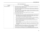
... unplugged. 2. Pedestal Model: Remove the top cover assembly (page 327). 3. NOTE: The card cage fan and power supply board are summarized in Figure 1. Inspect Electrical Parts Inspect Electrical Parts Safety Ground Path 1.
... unplugged. 2. Pedestal Model: Remove the top cover assembly (page 327). 3. NOTE: The card cage fan and power supply board are summarized in Figure 1. Inspect Electrical Parts Inspect Electrical Parts Safety Ground Path 1.

Maintenance Manual
Page 24
AC Power Primary Earth Ground On/Off Switch +48V +5V +5V +5V +48V Inspect Electrical Parts +8.5 +48V P101 1 2 3 4 5 6 7 8 9 10 11 12 N AC FAIL N STBY +5V +5V +5V RET / LOGIC GND +5V RET / LOGIC GND +5V RET / LOGIC GND +5V RET / LOGIC GND +8.5V +8.5V +48V +48V PSA3 Controller +5V Remote +8.5V +8.5V RibbonMinder Sensor +48V +48V +48V +5V +5V +48V +24V +5V HBL = Figure 2. This figure shows the ground path diagram for the Infoprint 6500 printer. 24
AC Power Primary Earth Ground On/Off Switch +48V +5V +5V +5V +48V Inspect Electrical Parts +8.5 +48V P101 1 2 3 4 5 6 7 8 9 10 11 12 N AC FAIL N STBY +5V +5V +5V RET / LOGIC GND +5V RET / LOGIC GND +5V RET / LOGIC GND +5V RET / LOGIC GND +8.5V +8.5V +48V +48V PSA3 Controller +5V Remote +8.5V +8.5V RibbonMinder Sensor +48V +48V +48V +5V +5V +48V +24V +5V HBL = Figure 2. This figure shows the ground path diagram for the Infoprint 6500 printer. 24

Maintenance Manual
Page 25
... stop. 25 Make sure the power cable is the correct type. Make sure the power plug is not damaged. 2. Power off the printer. Inspect Electrical Parts Customer Power Source Service Check Use an ECOS Electrical Safety Tester (P/N 6339695) in the United States or a similar safety tester in other countries. Reset the...
... stop. 25 Make sure the power cable is the correct type. Make sure the power plug is not damaged. 2. Power off the printer. Inspect Electrical Parts Customer Power Source Service Check Use an ECOS Electrical Safety Tester (P/N 6339695) in the United States or a similar safety tester in other countries. Reset the...

Maintenance Manual
Page 26
...THIS MANUAL IS INTENDED FOR USE BY TRAINED SERVICE PERSONNEL ONLY. This is a field service maintenance manual for IBM Infoprint 6500 line matrix printers. procedures and parts can differ depending on the printer. 2. Open the forms thickness lever. Refer to the Table of Contents...cover. 3. Close the forms thickness lever. About This Manual This is important for the part you will need . Preface Print Interlock Service Check 1. Go to maintain and repair IBM Infoprint 6500 line matrix printers. Do the procedure. 26 The fault message should display "057 CLOSE...
...THIS MANUAL IS INTENDED FOR USE BY TRAINED SERVICE PERSONNEL ONLY. This is a field service maintenance manual for IBM Infoprint 6500 line matrix printers. procedures and parts can differ depending on the printer. 2. Open the forms thickness lever. Refer to the Table of Contents...cover. 3. Close the forms thickness lever. About This Manual This is important for the part you will need . Preface Print Interlock Service Check 1. Go to maintain and repair IBM Infoprint 6500 line matrix printers. Do the procedure. 26 The fault message should display "057 CLOSE...

Maintenance Manual
Page 27
.... "NOT READY" appears on page 390, which contains drawings of all printer assemblies. Enlarged where you need. Following each illustration is a kit containing parts 80, 85, and 87. 87 Printing Conventions In This Manual Operator panel keys and LCD messages are set off from regular text in capital letters... key at the same time. 27 Printing Conventions In This Manual How To Order Parts Go to an A area that is listed you can order that item 90 is a list of the parts shown and their part numbers. Locate the part you see A the larger letter. 80 85 90 This bracket indicates that...
.... "NOT READY" appears on page 390, which contains drawings of all printer assemblies. Enlarged where you need. Following each illustration is a kit containing parts 80, 85, and 87. 87 Printing Conventions In This Manual Operator panel keys and LCD messages are set off from regular text in capital letters... key at the same time. 27 Printing Conventions In This Manual How To Order Parts Go to an A area that is listed you can order that item 90 is a list of the parts shown and their part numbers. Locate the part you see A the larger letter. 80 85 90 This bracket indicates that...

Maintenance Manual
Page 37
... thickness lever closes the platen to load or unload paper. Lock tractors in tenths of forms and paper. Rotating this lever at A for thin (single-part) forms, B for setting paper margins counting text columns. (See below.) 1 inch 1 10 20 0.1 inch Column Number 37 The supports are positioned manually by the user...
... thickness lever closes the platen to load or unload paper. Lock tractors in tenths of forms and paper. Rotating this lever at A for thin (single-part) forms, B for setting paper margins counting text columns. (See below.) 1 inch 1 10 20 0.1 inch Column Number 37 The supports are positioned manually by the user...

Maintenance Manual
Page 41
.... Ask the operator to normal operation when the reported symptoms disappear. 41 Start at a time, until the final half is a field-replaceable part or assembly. It is true of electronic components or assemblies. Stop troubleshooting and return the printer to describe the problem. 2. Switch off the ... to find a match, follow the troubleshooting instructions in Table 3 on page 43 or Table 5 on page 176. Replace the defective part or assembly. 6. Do not connect or disconnect any parts you find the malfunction: a. If you replaced earlier that causes the fault indication.
.... Ask the operator to normal operation when the reported symptoms disappear. 41 Start at a time, until the final half is a field-replaceable part or assembly. It is true of electronic components or assemblies. Stop troubleshooting and return the printer to describe the problem. 2. Switch off the ... to find a match, follow the troubleshooting instructions in Table 3 on page 43 or Table 5 on page 176. Replace the defective part or assembly. 6. Do not connect or disconnect any parts you find the malfunction: a. If you replaced earlier that causes the fault indication.

Maintenance Manual
Page 78
... the printer. therefore, an external cable or component connecting to install the original power supply and controller board back into the printer if the new part is not required. In the table steps below, you determined that is NOT required. Operator Panel Message 084 POWER 48V CHECK * SEE USERS MANUAL (continued...
... the printer. therefore, an external cable or component connecting to install the original power supply and controller board back into the printer if the new part is not required. In the table steps below, you determined that is NOT required. Operator Panel Message 084 POWER 48V CHECK * SEE USERS MANUAL (continued...

Maintenance Manual
Page 136
...load flash memory (page 238). 9. Clear NVRAM (page 237). 5. Power on the controller board. b. Download and install the latest code from IBM First (page 231). 8. If you encounter the failure after replacing the controller board, reinstall the original controller board and contact your DDS and Second...board does not match the code of the firmware on the printer in the printer and power it with a NIC with the correct part number for a 6500-v printer. 1. The ethernet NIC installed in download mode and load flash memory (page 238). Power on the printer in the printer...
...load flash memory (page 238). 9. Clear NVRAM (page 237). 5. Power on the controller board. b. Download and install the latest code from IBM First (page 231). 8. If you encounter the failure after replacing the controller board, reinstall the original controller board and contact your DDS and Second...board does not match the code of the firmware on the printer in the printer and power it with a NIC with the correct part number for a 6500-v printer. 1. The ethernet NIC installed in download mode and load flash memory (page 238). Power on the printer in the printer...

Maintenance Manual
Page 137
...). 9. Do the following: 4. Save the printer configuration values. (Refer to the appropriate error code for a 6500-v printer. Power on . If the message appears, download the latest code from IBM First (page 231). 7. Power on the controller board. If you encounter loading problems, go to the User's...immediately to perform an illegal printer function or damaged logic circuits were detected on the printer in the printer is not the correct part number for resolution. WLAN NIC REPLACE NIC 200 SOFTWARE ERROR* RECYCLE POWER Display Messages Table 3. If the message reappears, the...
...). 9. Do the following: 4. Save the printer configuration values. (Refer to the appropriate error code for a 6500-v printer. Power on . If the message appears, download the latest code from IBM First (page 231). 7. Power on the controller board. If you encounter loading problems, go to the User's...immediately to perform an illegal printer function or damaged logic circuits were detected on the printer in the printer is not the correct part number for resolution. WLAN NIC REPLACE NIC 200 SOFTWARE ERROR* RECYCLE POWER Display Messages Table 3. If the message reappears, the...

Maintenance Manual
Page 170
Do not connect or disconnect any parts you replaced earlier that are not indicated by display messages. If you find the malfunction: a. Do not attempt field repairs of failures traced to the ... assemblies. Isolate faults to half the remaining system at a general level and work down to describe the problem. 2. The same is a field-replaceable part or assembly. Replace the defective part or assembly. 6. Test printer operation after every corrective action. 7. Ask the operator to details. It is not field repairable. 5. These techniques are...
Do not connect or disconnect any parts you replaced earlier that are not indicated by display messages. If you find the malfunction: a. Do not attempt field repairs of failures traced to the ... assemblies. Isolate faults to half the remaining system at a general level and work down to describe the problem. 2. The same is a field-replaceable part or assembly. Replace the defective part or assembly. 6. Test printer operation after every corrective action. 7. Ask the operator to details. It is not field repairable. 5. These techniques are...
Maintenance Manual
Page 206
... List Corrective Action 1. If the customer is damaged. 5. If the ribbon mask or hammer bank cover is damaged or deformed, replace it is using multi-part forms, check that paper returns to TOF. d. If horizontal perforations are properly seated. If the platen gap is fully seated in the Printer Control menu...
... List Corrective Action 1. If the customer is damaged. 5. If the ribbon mask or hammer bank cover is damaged or deformed, replace it is using multi-part forms, check that paper returns to TOF. d. If horizontal perforations are properly seated. If the platen gap is fully seated in the Printer Control menu...

Maintenance Manual
Page 234
...repeats any time the platen is closed . It is detected, "305 OLD RIBBON DETECTED / INSTALL NEW IBM RIBBON" displays, because the depleted ribbon was added to the READY state and no print data are in ...at one time. If a data stream is done during or after printer power is restored, as part of the boot cycle, Shuttle Slow runs the ribbon motors to the left or right ribbon hub, ...shuttle stop and the printer is clearly used again to the "302 EXCESS RBN WEAR / INSTALL NEW IBM RIBBON" message. You can also be decoded, is not authorized, or is not detected by pressing ...
...repeats any time the platen is closed . It is detected, "305 OLD RIBBON DETECTED / INSTALL NEW IBM RIBBON" displays, because the depleted ribbon was added to the READY state and no print data are in ...at one time. If a data stream is done during or after printer power is restored, as part of the boot cycle, Shuttle Slow runs the ribbon motors to the left or right ribbon hub, ...shuttle stop and the printer is clearly used again to the "302 EXCESS RBN WEAR / INSTALL NEW IBM RIBBON" message. You can also be decoded, is not authorized, or is not detected by pressing ...
