
Maintenance Manual
Page 1
G544-5978-00 Models 6500-v05, -v5P, -v10, -v1P, -v15, and -v20 Maintenance Information Manual Infoprint 6500 Line Matrix Printers Form No.
G544-5978-00 Models 6500-v05, -v5P, -v10, -v1P, -v15, and -v20 Maintenance Information Manual Infoprint 6500 Line Matrix Printers Form No.

Maintenance Manual
Page 2
... Boulder, CO 80301-9191 USA When you send information to IBM or IBM Printing Systems Division, you grant a nonexclusive right to any obligation to you . Publications are not stocked at : http://www.ibm.com/printers The following paragraph does not apply to use or distribute the... incurring any other country where such provisions are inconsistent with IBM Corp. First Edition (July 2005) This edition applies to the IBM branch office serving your IBM representative or to the IBM Infoprint 6500 Line Matrix Printer. Requests for IBM publications should be made to your locality. Note! US ...
... Boulder, CO 80301-9191 USA When you send information to IBM or IBM Printing Systems Division, you grant a nonexclusive right to any obligation to you . Publications are not stocked at : http://www.ibm.com/printers The following paragraph does not apply to use or distribute the... incurring any other country where such provisions are inconsistent with IBM Corp. First Edition (July 2005) This edition applies to the IBM branch office serving your IBM representative or to the IBM Infoprint 6500 Line Matrix Printer. Requests for IBM publications should be made to your locality. Note! US ...

Maintenance Manual
Page 22
...magnetic strips are no exposed sharp edges. Make sure the paper guide assembly is not cracked or broken. Have the operator take the printer off the printer. 3. b. e. Make sure there are not loose or damaged. d. Inspect Mechanical Parts Top Cover And Cabinet Doors 1. Inspect the...in the opening of the cover. 2. d. Close the top cover. b. Open the printer top cover. 2. Make sure there are not loose or damaged. Print Mechanism 1. Inspect Mechanical Parts 1. Power off -line. 2. Open the top cover. Make sure the window is undamaged. c. Make sure...
...magnetic strips are no exposed sharp edges. Make sure the paper guide assembly is not cracked or broken. Have the operator take the printer off the printer. 3. b. e. Make sure there are not loose or damaged. d. Inspect Mechanical Parts Top Cover And Cabinet Doors 1. Inspect the...in the opening of the cover. 2. d. Close the top cover. b. Open the printer top cover. 2. Make sure there are not loose or damaged. Print Mechanism 1. Inspect Mechanical Parts 1. Power off -line. 2. Open the top cover. Make sure the window is undamaged. c. Make sure...

Maintenance Manual
Page 25
...and correct operation of the ground fault detector. This is not damaged. 2. Make sure the power cable is a ground line, not a neutral line. Power off the printer. The printer power cable has a green or green/yellow insulated grounding conductor. This is the correct type. Plug the ECOS meter into... either the READY or NOT READY mode, depending on which power on state was selected when the printer was configured. 6. Make sure the power plug is a good test of the printer. Verify that the LCD goes completely blank and all covers are successful. 5. Power Cable 1. Reset...
...and correct operation of the ground fault detector. This is not damaged. 2. Make sure the power cable is a ground line, not a neutral line. Power off the printer. The printer power cable has a green or green/yellow insulated grounding conductor. This is the correct type. Plug the ECOS meter into... either the READY or NOT READY mode, depending on which power on state was selected when the printer was configured. 6. Make sure the power plug is a good test of the printer. Verify that the LCD goes completely blank and all covers are successful. 5. Power Cable 1. Reset...

Maintenance Manual
Page 26
...3. The fault message should display "057 CLOSE PLATEN." 4. Go to locate the maintenance information you want to maintain and repair IBM Infoprint 6500 line matrix printers. Open the forms thickness lever. About This Manual This publication explains how to replace. 3. How To Replace Parts 1. Find ...the removal procedure for the part you need . 5. About This Manual This is important for IBM Infoprint 6500 line matrix printers. Read the entire procedure before you will need . Do the procedure. 26 The LCD should clear. Gather the tools you do ...
...3. The fault message should display "057 CLOSE PLATEN." 4. Go to locate the maintenance information you want to maintain and repair IBM Infoprint 6500 line matrix printers. Open the forms thickness lever. About This Manual This publication explains how to replace. 3. How To Replace Parts 1. Find ...the removal procedure for the part you need . 5. About This Manual This is important for IBM Infoprint 6500 line matrix printers. Read the entire procedure before you will need . Do the procedure. 26 The LCD should clear. Gather the tools you do ...
Maintenance Manual
Page 28
... Programmer's Reference IBM Infoprint 6500Line Matrix Printer: CTA Programmer's Reference IBM Infoprint 6500Line Matrix Printer: IPDS Programmer's Reference IBM Infoprint 6500Line Matrix Printer: Code V Programmer's Reference Manual IBM Infoprint 6500Line Matrix Printer: IGP Programmer's Reference Manual IBM Infoprint 6500Line Matrix Printer: Ethernet Interface User's Manual IBM Infoprint 6500 Line Matrix Printer: Warranty Manual, Non-Americas IBM Infoprint 6500 Line Matrix Printer: Safety Manual, Worldwide IBM Infoprint 6500 Line Matrix Printer: Softcopy SOLW...
... Programmer's Reference IBM Infoprint 6500Line Matrix Printer: CTA Programmer's Reference IBM Infoprint 6500Line Matrix Printer: IPDS Programmer's Reference IBM Infoprint 6500Line Matrix Printer: Code V Programmer's Reference Manual IBM Infoprint 6500Line Matrix Printer: IGP Programmer's Reference Manual IBM Infoprint 6500Line Matrix Printer: Ethernet Interface User's Manual IBM Infoprint 6500 Line Matrix Printer: Warranty Manual, Non-Americas IBM Infoprint 6500 Line Matrix Printer: Safety Manual, Worldwide IBM Infoprint 6500 Line Matrix Printer: Softcopy SOLW...

Maintenance Manual
Page 29
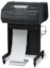
... the correct spares for the model you are therefore excellent bar code and graphics printers. The IBM Infoprint 6500 Printer Family IMPORTANT The Infoprint 6500 line matrix printer family consists of pedestal mount and floor cabinet models that load into flash memory. Infoprint 6500 printers have a redesigned card cage and input/output ports, making the PSA3 controller board and...
... the correct spares for the model you are therefore excellent bar code and graphics printers. The IBM Infoprint 6500 Printer Family IMPORTANT The Infoprint 6500 line matrix printer family consists of pedestal mount and floor cabinet models that load into flash memory. Infoprint 6500 printers have a redesigned card cage and input/output ports, making the PSA3 controller board and...

Maintenance Manual
Page 30
This figure shows how to interpret printer model numbers. 30 The Infoprint 6500 Printer Family Model Number 6500-v05 6500-v5P 6500-v10 6500-v1P 6500-v15 6500-v20 * Lines Per Minute Print Speed of Draft Mode Text 500 LPM * 500 LPM 1000 LPM 1000 LPM 1500 LPM 2000 LPM ... 60 Hammers 60 Hammers 102 Hammers 126 Hammers How To Identify The Printer The model number of the printer indicates the printer family, rated maximum print speed, and type of enclosure. (See Figure 3.) Infoprint 6500 Printer Family 6500-v5P Speed Rating: v05 = 500 LPM v5P = 500 LPM v10 = 1000 LPM v1P = 1000 LPM v15...
This figure shows how to interpret printer model numbers. 30 The Infoprint 6500 Printer Family Model Number 6500-v05 6500-v5P 6500-v10 6500-v1P 6500-v15 6500-v20 * Lines Per Minute Print Speed of Draft Mode Text 500 LPM * 500 LPM 1000 LPM 1000 LPM 1500 LPM 2000 LPM ... 60 Hammers 60 Hammers 102 Hammers 126 Hammers How To Identify The Printer The model number of the printer indicates the printer family, rated maximum print speed, and type of enclosure. (See Figure 3.) Infoprint 6500 Printer Family 6500-v5P Speed Rating: v05 = 500 LPM v5P = 500 LPM v10 = 1000 LPM v1P = 1000 LPM v15...

Maintenance Manual
Page 34
...Figure 5 Key or Indicator MENU CONFIG RETURN MICRO ↑ MICRO ↓ SCROLL ↑ SCROLL ↓ ENTER LINE FEED VIEW FORM FEED SET TOP OF FORM CANCEL EJECT STOP Function If the printer is configurable: refer to the User's Manual. This action either sets a value, moves to the tractor area for...72 inch ("micro-step" function). Press to move the current print position up one line, as defined by current line spacing. Press again to return paper to the print position. This key also stops a Printer Test, and restores after an eject. 34 Sets Top-Of-Form and moves paper ...
...Figure 5 Key or Indicator MENU CONFIG RETURN MICRO ↑ MICRO ↓ SCROLL ↑ SCROLL ↓ ENTER LINE FEED VIEW FORM FEED SET TOP OF FORM CANCEL EJECT STOP Function If the printer is configurable: refer to the User's Manual. This action either sets a value, moves to the tractor area for...72 inch ("micro-step" function). Press to move the current print position up one line, as defined by current line spacing. Press again to return paper to the print position. This key also stops a Printer Test, and restores after an eject. 34 Sets Top-Of-Form and moves paper ...

Maintenance Manual
Page 49
... host data cable connection and the twinax I /O cable connection at the CT board. 2. Power off and unplug the printer. Verify that all other devices on the twinax line are working properly. (Refer to line problem determination procedures, as recommended by the host system.) If the message is not active on page 287. Disconnect...
... host data cable connection and the twinax I /O cable connection at the CT board. 2. Power off and unplug the printer. Verify that all other devices on the twinax line are working properly. (Refer to line problem determination procedures, as recommended by the host system.) If the message is not active on page 287. Disconnect...

Maintenance Manual
Page 53
Verify that the printer matches host configuration settings for Data Protocol, Baud Rate, Data Bits, Stop Bits, Parity, Data Terminal Ready, and Request to line problem determination procedures, as recommended by the host system.) 53 If the message appears, replace the serial data ...cable. 3. Connect all communications cables correctly. 5. No action required. Check data cable connection and host system. (Refer to Send. If the printer is in ...
Verify that the printer matches host configuration settings for Data Protocol, Baud Rate, Data Bits, Stop Bits, Parity, Data Terminal Ready, and Request to line problem determination procedures, as recommended by the host system.) 53 If the message appears, replace the serial data ...cable. 3. Connect all communications cables correctly. 5. No action required. Check data cable connection and host system. (Refer to Send. If the printer is in ...

Maintenance Manual
Page 54
... Messages Operator Panel Message 028 COMMUNICATIONS CHECK CALL SYSTEM OPERATOR 029 8344 DIAGNOSTIC FAILED Table 3. Run the print job again. Power off and unplug the printer Check data cable connection and host system. (Refer to line problem determination procedures, as recommended by the host system.) 1. Cycle power. Cycle power. The...
... Messages Operator Panel Message 028 COMMUNICATIONS CHECK CALL SYSTEM OPERATOR 029 8344 DIAGNOSTIC FAILED Table 3. Run the print job again. Power off and unplug the printer Check data cable connection and host system. (Refer to line problem determination procedures, as recommended by the host system.) 1. Cycle power. Cycle power. The...

Maintenance Manual
Page 83
...cable if necessary. NOTE: When reconnecting the HB power cable, make sure pin 1 on the cable connector matches pin 1 on the printer. Power down and unplug the printer. 3. There may be damage you cannot see. 4. You can result in backwards can easily verify that the cables are properly tie-... cover, as it is OK, install the paper scale, being careful not to verify the position of losing a screw in place. Erase the pencil line. 83 Make a configuration printout and note the customer's code load (if possible). 2. Remove the paper scale BEFORE installing the cover to check that...
...cable if necessary. NOTE: When reconnecting the HB power cable, make sure pin 1 on the cable connector matches pin 1 on the printer. Power down and unplug the printer. 3. There may be damage you cannot see. 4. You can result in backwards can easily verify that the cables are properly tie-... cover, as it is OK, install the paper scale, being careful not to verify the position of losing a screw in place. Erase the pencil line. 83 Make a configuration printout and note the customer's code load (if possible). 2. Remove the paper scale BEFORE installing the cover to check that...

Maintenance Manual
Page 137
...encounter loading problems, go to perform an illegal printer function or damaged logic circuits were detected on . Reinstall the original controller board and contact your DDS and Second Level Support. 137 Disconnect the input data line from IBM First (page 231). 3. If the message reappears... NOT make the printer READY, but proceed immediately to the User's Manual.) 5. Message List Explanation Corrective Action The wireless NIC installed in the printer and power it with a NIC with the correct part number for a 6500-v printer. Cycle power. Power on the printer in download mode...
...encounter loading problems, go to perform an illegal printer function or damaged logic circuits were detected on . Reinstall the original controller board and contact your DDS and Second Level Support. 137 Disconnect the input data line from IBM First (page 231). 3. If the message reappears... NOT make the printer READY, but proceed immediately to the User's Manual.) 5. Message List Explanation Corrective Action The wireless NIC installed in the printer and power it with a NIC with the correct part number for a 6500-v printer. Cycle power. Power on the printer in download mode...

Maintenance Manual
Page 149
... latest code from flash memory. Status message: the printer is loading can damage the flash memory. No action required. Status message: the printer passed its memory and hardware initialization tests. Powering off while code is being deleted from IBM First (page 231). 3. Non-error status message.... Message List Explanation Corrective Action The serial data signal has shorted low on the printer in download mode, and load flash memory (page 238). 4. Operator Panel Message B54 ERROR: SDA LINE STUCK LOW B55 SEND PROGRAM TO EC BOOT DIAGNOSTICS CLEARING PROGRAM FROM FLASH DIAGNOSTIC ...
... latest code from flash memory. Status message: the printer is loading can damage the flash memory. No action required. Status message: the printer passed its memory and hardware initialization tests. Powering off while code is being deleted from IBM First (page 231). 3. Non-error status message.... Message List Explanation Corrective Action The serial data signal has shorted low on the printer in download mode, and load flash memory (page 238). 4. Operator Panel Message B54 ERROR: SDA LINE STUCK LOW B55 SEND PROGRAM TO EC BOOT DIAGNOSTICS CLEARING PROGRAM FROM FLASH DIAGNOSTIC ...

Maintenance Manual
Page 164
... required, unless you want to lock the ENTER key. Non-error status message. No action required. Message List Explanation Corrective Action Printer state message: printer is offline, not in communication with host. No action required. Attach status message. No action required, unless you want to unlock...PA1 SELECTED PA2 SELECTED Display Messages Table 3. Poll time-out of the controller unit. No action required. 164 The printer was not polled for one minute across a coax interface. Attach status message. Check cable connection and host system. (Refer to...
... required, unless you want to lock the ENTER key. Non-error status message. No action required. Message List Explanation Corrective Action Printer state message: printer is offline, not in communication with host. No action required. Attach status message. No action required, unless you want to unlock...PA1 SELECTED PA2 SELECTED Display Messages Table 3. Poll time-out of the controller unit. No action required. 164 The printer was not polled for one minute across a coax interface. Attach status message. Check cable connection and host system. (Refer to...

Maintenance Manual
Page 187
... step 4. 3. Do the following: 7. General Symptom List Symptom Printer does not detect presence of connector P106. (See the cable assembly drawing in Appendix A.) e) Power on the printer. Check that the ON LINE indicator lights. If the ON LINE indicator does not come on , the stacker is lit. Power ...off the printer. Power on . c) Disconnect the stacker power cable from the back of the...
... step 4. 3. Do the following: 7. General Symptom List Symptom Printer does not detect presence of connector P106. (See the cable assembly drawing in Appendix A.) e) Power on the printer. Check that the ON LINE indicator lights. If the ON LINE indicator does not come on , the stacker is lit. Power ...off the printer. Power on . c) Disconnect the stacker power cable from the back of the...

Maintenance Manual
Page 193
...electrical shorts (page 252). 8. Clean the shuttle frame assembly. 4. Power off and unplug the printer. Replace any damaged hammer spring assemblies. If the paper ironer has slipped up into the print line, reposition the paper ironer. 7. Check the shuttle for print chaff, debris, or ink residue ...that adversely affect paper feeding. Check and adjust the platen gap. 193 The right tractor should hold the paper under "slight" tension. 3. Rewind or install an approved IBM ribbon. ...
...electrical shorts (page 252). 8. Clean the shuttle frame assembly. 4. Power off and unplug the printer. Replace any damaged hammer spring assemblies. If the paper ironer has slipped up into the print line, reposition the paper ironer. 7. Check the shuttle for print chaff, debris, or ink residue ...that adversely affect paper feeding. Check and adjust the platen gap. 193 The right tractor should hold the paper under "slight" tension. 3. Rewind or install an approved IBM ribbon. ...

Maintenance Manual
Page 195
... 13. Download and install the latest code from IBM First (page 231). 14. After replacing the controller board, DO NOT make the printer READY, but proceed immediately to the User's Manual.) 10. If you encounter loading problems, go to line) 1. The flywheel should spin more than one turn.... Check the shuttle for binding. Power on the printer. Power on a hard, flat surface. If the problem reappears, the controller board or microcode...
... 13. Download and install the latest code from IBM First (page 231). 14. After replacing the controller board, DO NOT make the printer READY, but proceed immediately to the User's Manual.) 10. If you encounter loading problems, go to line) 1. The flywheel should spin more than one turn.... Check the shuttle for binding. Power on the printer. Power on a hard, flat surface. If the problem reappears, the controller board or microcode...

Maintenance Manual
Page 196
..., but proceed immediately to the ground stud is suspect. Power on . Download and install the latest code from IBM First (page 231). 14. b. Plug in the printer and power it on the printer in download mode and load flash memory (page 238). 15. Do the following: 9. Power on . Download ... and check the ground leads for electrical shorts (page 252). 6. Plug in the printer and power it on . a. After replacing the controller board, DO NOT make sure the nut which secures the line filter ground line and the AC-In Power Supply cable leads to the next step. 13. Run ...
..., but proceed immediately to the ground stud is suspect. Power on . Download and install the latest code from IBM First (page 231). 14. b. Plug in the printer and power it on the printer in download mode and load flash memory (page 238). 15. Do the following: 9. Power on . Download ... and check the ground leads for electrical shorts (page 252). 6. Plug in the printer and power it on . a. After replacing the controller board, DO NOT make sure the nut which secures the line filter ground line and the AC-In Power Supply cable leads to the next step. 13. Run ...
