
Maintenance Manual
Page 46
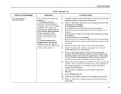
... Level Support. 19. Save the printer configuration values. (Refer to the print position. 46 Clear NVRAM (page 237). 14. Power on the printer in download mode and load flash memory (page 238). If the problem reappears, the controller board or microcode is suspect. Download and install the latest code from IBM First (page 231). 17. Non-error status message. At the operator panel, set the paper motion detector (PMD) to DISABLE. Do the following: 12. a. After replacing the controller board, DO NOT make...
... Level Support. 19. Save the printer configuration values. (Refer to the print position. 46 Clear NVRAM (page 237). 14. Power on the printer in download mode and load flash memory (page 238). If the problem reappears, the controller board or microcode is suspect. Download and install the latest code from IBM First (page 231). 17. Non-error status message. At the operator panel, set the paper motion detector (PMD) to DISABLE. Do the following: 12. a. After replacing the controller board, DO NOT make...
Maintenance Manual
Page 51
... next step. 5. Remove the paper guide assembly. Plug in download mode and load flash memory (page 238). 51 This will always occur if the user presses the ELEVATOR UP key on . Check continuity of its travel. 2. Disable the power stacker unit under the Printer Control menu. (Refer to the User's Manual.) 8. Clear NVRAM (page 237). 9. Power off and unplug the printer. Operate the power stacker and check that is suspect. Operator Panel Message 019 STACKER FAULT CHECK STACKER Display Messages Table 3. Tighten...
... next step. 5. Remove the paper guide assembly. Plug in download mode and load flash memory (page 238). 51 This will always occur if the user presses the ELEVATOR UP key on . Check continuity of its travel. 2. Disable the power stacker unit under the Printer Control menu. (Refer to the User's Manual.) 8. Clear NVRAM (page 237). 9. Power off and unplug the printer. Operate the power stacker and check that is suspect. Operator Panel Message 019 STACKER FAULT CHECK STACKER Display Messages Table 3. Tighten...

Maintenance Manual
Page 55
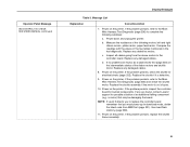
... in download mode and load flash memory (page 238). Download and install the latest code from IBM First (page 231). 10. Power on the printer in the printer and power it on . Operator Panel Message 031 END OF FORMS TMEOUT LOAD FORMS Display Messages Table 3. Check that connector P106/PMD is optical and may not detect paper with a black-back forms switch assembly. 3. Load paper. Press STOP. The paper out detector is fully seated in its bracket. 4. Replace the paper detector switch...
... in download mode and load flash memory (page 238). Download and install the latest code from IBM First (page 231). 10. Power on the printer in the printer and power it on . Operator Panel Message 031 END OF FORMS TMEOUT LOAD FORMS Display Messages Table 3. Check that connector P106/PMD is optical and may not detect paper with a black-back forms switch assembly. 3. Load paper. Press STOP. The paper out detector is fully seated in its bracket. 4. Replace the paper detector switch...

Maintenance Manual
Page 58
... IBM First (page 231). 17. Download and install the latest code from IBM First (page 231). 15. Power on the printer in download mode and load flash memory (page 238). Clean the paper motion detector with a cotton swab and alcohol. Load paper. Power on the printer in download mode and load flash memory (page 238). 18. If the message does not appear, replace the paper detector switch assembly and set the paper motion detector (PMD) fault setting to ENABLE. 58 If you to the appropriate error code...
... IBM First (page 231). 17. Download and install the latest code from IBM First (page 231). 15. Power on the printer in download mode and load flash memory (page 238). Clean the paper motion detector with a cotton swab and alcohol. Load paper. Power on the printer in download mode and load flash memory (page 238). 18. If the message does not appear, replace the paper detector switch assembly and set the paper motion detector (PMD) fault setting to ENABLE. 58 If you to the appropriate error code...

Maintenance Manual
Page 65
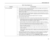
... this test, replace the shuttle frame assembly. 17. a. b. Download and install the latest code from IBM First (page 231). 12. If it on the printer in download mode and load flash memory (page 238). 15. Rotate the flywheel by hand and check for resolution. The flywheel should spin more than one turn. Display Messages Operator Panel Message 058 SHUTL JAM SEE USERS MANUAL (continued) 059 CANCEL PRINT ACTIVE Table 3. Message List Explanation Corrective Action Non-error status message. 8. If the problem...
... this test, replace the shuttle frame assembly. 17. a. b. Download and install the latest code from IBM First (page 231). 12. If it on the printer in download mode and load flash memory (page 238). 15. Rotate the flywheel by hand and check for resolution. The flywheel should spin more than one turn. Display Messages Operator Panel Message 058 SHUTL JAM SEE USERS MANUAL (continued) 059 CANCEL PRINT ACTIVE Table 3. Message List Explanation Corrective Action Non-error status message. 8. If the problem...

Maintenance Manual
Page 66
... printer. Remove the paper guide assembly or pedestal top cover. Remove any obstructions from IBM First (page 231). 11. Install the paper guide assembly or pedestal top cover. Clear NVRAM (page 237). 8. Power on the board. Inspect printer environment for items blocking the cabinet exhaust vents. If you encounter loading problems, go to a cooler, cleaner area. 1. After replacing the controller board, DO NOT make the printer READY, but proceed immediately to the User's Manual...
... printer. Remove the paper guide assembly or pedestal top cover. Remove any obstructions from IBM First (page 231). 11. Install the paper guide assembly or pedestal top cover. Clear NVRAM (page 237). 8. Power on the board. Inspect printer environment for items blocking the cabinet exhaust vents. If you encounter loading problems, go to a cooler, cleaner area. 1. After replacing the controller board, DO NOT make the printer READY, but proceed immediately to the User's Manual...

Maintenance Manual
Page 76
..., put on the printer in download mode and load flash memory (page 238). Verify that occurred before the 084 error. This is a long distance away, also obtain a shutlle assembly. Display Messages Operator Panel Message 083 INTAKE FAN CHECK * SEE USERS MANUAL (continued) 084 POWER 48V CHECK * SEE USERS MANUAL Table 3. Remove the paper guide assembly or pedestal top cover. Spin the flywheel by conducting the Shuttle Electrical Shorts Test on a hard, flat surface. Replace the PS if...
..., put on the printer in download mode and load flash memory (page 238). Verify that occurred before the 084 error. This is a long distance away, also obtain a shutlle assembly. Display Messages Operator Panel Message 083 INTAKE FAN CHECK * SEE USERS MANUAL (continued) 084 POWER 48V CHECK * SEE USERS MANUAL Table 3. Remove the paper guide assembly or pedestal top cover. Spin the flywheel by conducting the Shuttle Electrical Shorts Test on a hard, flat surface. Replace the PS if...
Maintenance Manual
Page 84
... USERS MANUAL (continued) Display Messages Table 3. Power on the printer. NOTE: If Level 2 directs you to the controller board. If the problem persists, replace the shuttle frame assembly. 84 Message List Explanation Corrective Action 7. If the problem persists, refer to the Main Wire Harness Test Diagnostic (page 256) to the Main Wire Harness Test Diagnostic (page 256) and check the shuttle motor. b. Inspect all cables going from IBM First (page 231), then load flash memory (page...
... USERS MANUAL (continued) Display Messages Table 3. Power on the printer. NOTE: If Level 2 directs you to the controller board. If the problem persists, replace the shuttle frame assembly. 84 Message List Explanation Corrective Action 7. If the problem persists, refer to the Main Wire Harness Test Diagnostic (page 256) to the Main Wire Harness Test Diagnostic (page 256) and check the shuttle motor. b. Inspect all cables going from IBM First (page 231), then load flash memory (page...

Maintenance Manual
Page 104
.... Remove the paper guide assembly or pedestal top cover. Power on the controller board. 3. After replacing the controller board, DO NOT make the printer READY, but proceed immediately to the User's Manual.) 7. Make sure connectors P106 and P107 are undamaged and have good connections. If the problem reappears, the controller board or microcode is suspect. a. Clear NVRAM (page 237). 8. Download and install the latest code from IBM First (page 231). 11. Run the print job...
.... Remove the paper guide assembly or pedestal top cover. Power on the controller board. 3. After replacing the controller board, DO NOT make the printer READY, but proceed immediately to the User's Manual.) 7. Make sure connectors P106 and P107 are undamaged and have good connections. If the problem reappears, the controller board or microcode is suspect. a. Clear NVRAM (page 237). 8. Download and install the latest code from IBM First (page 231). 11. Run the print job...

Maintenance Manual
Page 106
... printer READY, but proceed immediately to the User's Manual.) 9. Run the print job again. Remove the paper guide assembly or pedestal top cover. If the problem reappears, the controller board or microcode is suspect. Download and install the latest code from IBM First (page 231). 11. If you to the appropriate error code for shorts (page 252). 6. Firmware error on . Check hammer phasing (page 381). Check the shuttle for resolution. Plug in download mode and load flash memory (page 238). Clear...
... printer READY, but proceed immediately to the User's Manual.) 9. Run the print job again. Remove the paper guide assembly or pedestal top cover. If the problem reappears, the controller board or microcode is suspect. Download and install the latest code from IBM First (page 231). 11. If you to the appropriate error code for shorts (page 252). 6. Firmware error on . Check hammer phasing (page 381). Check the shuttle for resolution. Plug in download mode and load flash memory (page 238). Clear...

Maintenance Manual
Page 161
... bank cables are connected. 1. If the message appears, the controller board or microcode is suspect. Download and install the latest code from IBM First (page 231). 9. If the message appears, replace the shuttle frame assembly. Do the following: 4. If you to the appropriate error code for electrical shorts (page 252). 2. Power on the printer in download mode and load flash memory (page 238). 10. Power on the printer. Check the shuttle for resolution. Save the printer configuration...
... bank cables are connected. 1. If the message appears, the controller board or microcode is suspect. Download and install the latest code from IBM First (page 231). 9. If the message appears, replace the shuttle frame assembly. Do the following: 4. If you to the appropriate error code for electrical shorts (page 252). 2. Power on the printer in download mode and load flash memory (page 238). 10. Power on the printer. Check the shuttle for resolution. Save the printer configuration...
Maintenance Manual
Page 176
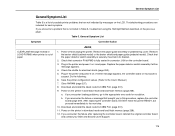
... and paper guide (pedestal model). Load paper. After replacing the controller board, DO NOT make the printer READY, but proceed immediately to the User's Manual.) 7. Power on . General Symptom List Symptom Corrective Action CLEAR JAM message instead of LOAD FORMS when printer is out of possible printer problems that are included for electrical shorts (page 252). 5. Check that connector P106/PMD is securely mounted in download mode and load flash memory (page 238). 12. Check that the paper detector switch assembly...
... and paper guide (pedestal model). Load paper. After replacing the controller board, DO NOT make the printer READY, but proceed immediately to the User's Manual.) 7. Power on . General Symptom List Symptom Corrective Action CLEAR JAM message instead of LOAD FORMS when printer is out of possible printer problems that are included for electrical shorts (page 252). 5. Check that connector P106/PMD is securely mounted in download mode and load flash memory (page 238). 12. Check that the paper detector switch assembly...

Maintenance Manual
Page 204
... download mode and load flash memory (page 238). Download and install the latest code from connector J110 on . Refer to the appropriate error code for resolution. Remove the paper guide assembly or pedestal top cover. Disconnect the operator panel cable from IBM First (page 231). 10. Load paper. Run a self test. If you to the User's Manual.) 6. b. If you encounter the failure after replacing the controller board, reinstall the original controller board and contact your DDS and Second Level Support...
... download mode and load flash memory (page 238). Download and install the latest code from connector J110 on . Refer to the appropriate error code for resolution. Remove the paper guide assembly or pedestal top cover. Disconnect the operator panel cable from IBM First (page 231). 10. Load paper. Run a self test. If you to the User's Manual.) 6. b. If you encounter the failure after replacing the controller board, reinstall the original controller board and contact your DDS and Second Level Support...
Maintenance Manual
Page 206
... foreign matter. Remove the paper guide assembly or pedestal top cover. Power on the controller board. 8. Set the forms length to TOF. Check for distortion or misalignment. Inspect the paper ironer for heavily tented horizontal perforations in the Printer Control menu) to Open. (Refer to the User's Manual.) 4. Correct as necessary. 7. Symptom TOF is correct, remove the shuttle frame assembly (page 362) and check the following: a. Replace the belt...
... foreign matter. Remove the paper guide assembly or pedestal top cover. Power on the controller board. 8. Set the forms length to TOF. Check for distortion or misalignment. Inspect the paper ironer for heavily tented horizontal perforations in the Printer Control menu) to Open. (Refer to the User's Manual.) 4. Correct as necessary. 7. Symptom TOF is correct, remove the shuttle frame assembly (page 362) and check the following: a. Replace the belt...
Maintenance Manual
Page 216
... available to the user through his documentation. CE tests do not run at the rated speed of printer tests is a numeric unit only. Slot 8 in increments of Forms Adjust 1 -1000 NOTE: Value is included in 1 second increments (On printers with CT installed) ENABLE* DISABLE Demo Count 1 * 2 5 10 Continuous PRINTER MGMT Debug Port Cfg PRINTER MGMT Serial PRINTER MGMT Clear Password PRINTER MGMT Reboot w/Factory PRINTER MGMT MANAGER PORT NO. CE Tests NOTE: * = Default Value NOTE...
... available to the user through his documentation. CE tests do not run at the rated speed of printer tests is a numeric unit only. Slot 8 in increments of Forms Adjust 1 -1000 NOTE: Value is included in 1 second increments (On printers with CT installed) ENABLE* DISABLE Demo Count 1 * 2 5 10 Continuous PRINTER MGMT Debug Port Cfg PRINTER MGMT Serial PRINTER MGMT Clear Password PRINTER MGMT Reboot w/Factory PRINTER MGMT MANAGER PORT NO. CE Tests NOTE: * = Default Value NOTE...

Maintenance Manual
Page 226
.... 226 Printer Information Installed Memory Power On Time Printing Time Printer Strokes nnnnnnnnnnnn 11 Inch Pages To view options, press: SCROLL↑ SCROLL↓ ENTER RETURN To select an option press ENTER. Printing Time The cumulative time in hours that the printer has actually been printing. Installed Memory Displays the amount of RAM in Megabytes installed in testing. This figure shows the Printer Information Menu. Selecting And Running Tests Printer Information Menu You can...
.... 226 Printer Information Installed Memory Power On Time Printing Time Printer Strokes nnnnnnnnnnnn 11 Inch Pages To view options, press: SCROLL↑ SCROLL↓ ENTER RETURN To select an option press ENTER. Printing Time The cumulative time in hours that the printer has actually been printing. Installed Memory Displays the amount of RAM in Megabytes installed in testing. This figure shows the Printer Information Menu. Selecting And Running Tests Printer Information Menu You can...

Maintenance Manual
Page 231
... default settings, when ribbon life reaches 2% the message changes to each ribbon spool do not use the same identification sequence number. The user can be flipped over and re-used one that is not duplicated on special high-capacity ribbon spools and a photo-reflective sensor mounted beneath the right-hand ribbon spool. The operator panel status lamp flashes, but the printer continues to accept new print jobs...
... default settings, when ribbon life reaches 2% the message changes to each ribbon spool do not use the same identification sequence number. The user can be flipped over and re-used one that is not duplicated on special high-capacity ribbon spools and a photo-reflective sensor mounted beneath the right-hand ribbon spool. The operator panel status lamp flashes, but the printer continues to accept new print jobs...

Maintenance Manual
Page 232
... PRINTER CONTROL Interface Selection Display Language Print Direction Hex Print Mode Power On State Paper Jam Detection Forms Speed Set Platen at that this setting, press the SCROLL↓ or SCROLL↑ key to select "Darker +1" through "Darker +6" (SCROLL↓) or "Lighter -1" through "Lighter -10" (SCROLL↑), where each increment or decrement corresponds to a predetermined set for all printer configurations and cannot be set value (density). To change...
... PRINTER CONTROL Interface Selection Display Language Print Direction Hex Print Mode Power On State Paper Jam Detection Forms Speed Set Platen at that this setting, press the SCROLL↓ or SCROLL↑ key to select "Darker +1" through "Darker +6" (SCROLL↓) or "Lighter -1" through "Lighter -10" (SCROLL↑), where each increment or decrement corresponds to a predetermined set for all printer configurations and cannot be set value (density). To change...
Maintenance Manual
Page 250
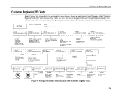
...: • P/N 39U2691 - This allows the end user or a service technician to enable features such as in Chapter 3 and follow the troubleshooting instructions. 6. When the printer detects a valid SPX, the operator panel displays: "NEW SPX DETECTED PRESS ENTER" NOTE: If an error message displays, find the message in the Message List in Figure 11. 4. 19. The SPX is used only once; Power off the printer. 2. On cabinet models, open the rear door.
...: • P/N 39U2691 - This allows the end user or a service technician to enable features such as in Chapter 3 and follow the troubleshooting instructions. 6. When the printer detects a valid SPX, the operator panel displays: "NEW SPX DETECTED PRESS ENTER" NOTE: If an error message displays, find the message in the Message List in Figure 11. 4. 19. The SPX is used only once; Power off the printer. 2. On cabinet models, open the rear door.

Maintenance Manual
Page 417
... Paper Detector Switch Assy Paper Detector Switch Assy Screw, Thread Forming, 6-32x.375 (2) Paper Feed Motor Assy, All Except Model v20 Paper Feed Motor Assy, Model v20 6 Ref Motor Pulley, Platen Open, Driver 7 Ref Screw, Hex w/Lock Washer (2) 8 39U2540 Ribbon Guide Cable Assembly, RH 39U2539 Ribbon Guide Cable Assembly, LH 9 54P1453 Platen Open ...is into card cage Two 6-32x1.75 on botton One 6-32x0.50 on the motor base and torque the mounting screws to 18 inch-pounds (2.03 N•m). Install it on top left Standard switch Black Back forms Model v20 only: Re-use the original...
... Paper Detector Switch Assy Paper Detector Switch Assy Screw, Thread Forming, 6-32x.375 (2) Paper Feed Motor Assy, All Except Model v20 Paper Feed Motor Assy, Model v20 6 Ref Motor Pulley, Platen Open, Driver 7 Ref Screw, Hex w/Lock Washer (2) 8 39U2540 Ribbon Guide Cable Assembly, RH 39U2539 Ribbon Guide Cable Assembly, LH 9 54P1453 Platen Open ...is into card cage Two 6-32x1.75 on botton One 6-32x0.50 on the motor base and torque the mounting screws to 18 inch-pounds (2.03 N•m). Install it on top left Standard switch Black Back forms Model v20 only: Re-use the original...


