Service Guide
Page 5
...and CMOS 16 Configuring the COM (communication) ports 16 Using the IBM Diagnostics for the SurePOS 500 Models 545 and 565 25 © Copyright IBM Corp. 2006 iii Removing and replacing FRUs for POS Systems and Peripherals package . . . . 16 Supported memory ...troubleshooting 19 Researching the Knowledgebase 19 Preliminary checklist 19 Troubleshooting symptoms and actions 20 CMOS recovery 23 Chapter 3. Introducing the IBM SurePOS 500 Series Models 545 and 565 1 Models and features 2 Optional features 4 Connectors, power, and brightness controls 5 Supported operating systems ...
...and CMOS 16 Configuring the COM (communication) ports 16 Using the IBM Diagnostics for the SurePOS 500 Models 545 and 565 25 © Copyright IBM Corp. 2006 iii Removing and replacing FRUs for POS Systems and Peripherals package . . . . 16 Supported memory ...troubleshooting 19 Researching the Knowledgebase 19 Preliminary checklist 19 Troubleshooting symptoms and actions 20 CMOS recovery 23 Chapter 3. Introducing the IBM SurePOS 500 Series Models 545 and 565 1 Models and features 2 Optional features 4 Connectors, power, and brightness controls 5 Supported operating systems ...
Service Guide
Page 26
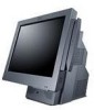
...APA - 12-in LCD v MSR: - 3-track - Introducing the SurePOS 500 Models 545 and 565 Optional features The following is a list of optional features available for single station printer, non-keyboard v Cash drawer v Compact A/N POS KEYBOARD v External USB floppy drive v USB antenna cover (accommodates USB ... v Wide cash drawer integration kit for the SurePOS 500: v Memory: - 512 MB DDR2 (standard) - 1 GB DDR2 v Displays: - Distributed 2x20 - excluding the exposed connector) v Side cover to accommodate PC Card antennas with lengths up to 119 mm 4 Models 545 and 565 Hardware Service Guide
...APA - 12-in LCD v MSR: - 3-track - Introducing the SurePOS 500 Models 545 and 565 Optional features The following is a list of optional features available for single station printer, non-keyboard v Cash drawer v Compact A/N POS KEYBOARD v External USB floppy drive v USB antenna cover (accommodates USB ... v Wide cash drawer integration kit for the SurePOS 500: v Memory: - 512 MB DDR2 (standard) - 1 GB DDR2 v Displays: - Distributed 2x20 - excluding the exposed connector) v Side cover to accommodate PC Card antennas with lengths up to 119 mm 4 Models 545 and 565 Hardware Service Guide
Service Guide
Page 38
...of-day clock and a calendar. Some previous SurePOS 500 system units utilized PCI-based COM ports with a shared IRQ. Select Support on the IBM Diagnostics for the SurePOS 500 Models 545 and 565 are not supported or required.) Use...IBM POS I /O address and the IRQ. Obtain a memory key. The system BIOS configures the COM ports for the location of the panel, then select IBM SurePOS 500/600 Series. 4. Locate the instructions for Models 545 and 565 provides a list of the 4846 product uses a unique I /O and IRQ value. Next, select SurePOS 500-xx5 Downloads. 5. The IBM SurePOS 500...
...of-day clock and a calendar. Some previous SurePOS 500 system units utilized PCI-based COM ports with a shared IRQ. Select Support on the IBM Diagnostics for the SurePOS 500 Models 545 and 565 are not supported or required.) Use...IBM POS I /O address and the IRQ. Obtain a memory key. The system BIOS configures the COM ports for the location of the panel, then select IBM SurePOS 500/600 Series. 4. Locate the instructions for Models 545 and 565 provides a list of the 4846 product uses a unique I /O and IRQ value. Next, select SurePOS 500-xx5 Downloads. 5. The IBM SurePOS 500...
Service Guide
Page 39
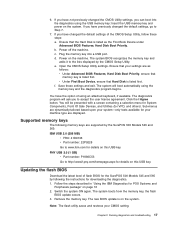
...to the lists displayed by following memory keys are supported by the SurePOS 500 Models 545 and 565: IBM USB 2.0 (256 MB) v FRU: 41D9746 v Part number: 22P9228 Go to Step 7. 7. You have not previously changed the default settings, go to www.ibm.com for details on the system. PNY USB 2.0 (1 GB... First Book Device under Advanced BIOS Features, Hard Disk Boot Priority. Follow the steps described in "Using the IBM Diagnostics for your system-only tests available for POS Systems and Peripherals package" on the machine. The system boots from the memory key, the flash BIOS update ...
...to the lists displayed by following memory keys are supported by the SurePOS 500 Models 545 and 565: IBM USB 2.0 (256 MB) v FRU: 41D9746 v Part number: 22P9228 Go to Step 7. 7. You have not previously changed the default settings, go to www.ibm.com for details on the system. PNY USB 2.0 (1 GB... First Book Device under Advanced BIOS Features, Hard Disk Boot Priority. Follow the steps described in "Using the IBM Diagnostics for your system-only tests available for POS Systems and Peripherals package" on the machine. The system boots from the memory key, the flash BIOS update ...
Service Guide
Page 41
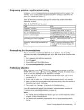
... LED stops blinking, POST is lit. 2. Chapter 3, "Removing and replacing FRUs for POS Systems and Peripherals package" on page 16 Appendix A, "Field replaceable parts," on page 25. Select IBM SurePOS 500/600 Series 4. Notes: 1. Preliminary checklist When you correctly adjust the brightness setting, using.... The following steps to help you can use the diagnostic service program to diagnose the problem. 1. "Using the IBM Diagnostics for the SurePOS 500 Models 545 and 565," on page 95. Go to help resolve problems. 2. Make sure that contains information supporting the task....
... LED stops blinking, POST is lit. 2. Chapter 3, "Removing and replacing FRUs for POS Systems and Peripherals package" on page 16 Appendix A, "Field replaceable parts," on page 25. Select IBM SurePOS 500/600 Series 4. Notes: 1. Preliminary checklist When you correctly adjust the brightness setting, using.... The following steps to help you can use the diagnostic service program to diagnose the problem. 1. "Using the IBM Diagnostics for the SurePOS 500 Models 545 and 565," on page 95. Go to help resolve problems. 2. Make sure that contains information supporting the task....

Service Guide
Page 80
...Unplug the MSR cable A , as shown in Figure 34 and remove the cable from the external power source. 2. After installation, run the diagnostics to the SurePOS 500. Switch OFF the power to ensure that secures the MSR. 4. Slide the MSR D up and off the MSR hole plug. 2. Use a screwdriver to pry... off . Remove the thumbscrew C that the MSR operates correctly. See "Using the IBM Diagnostics for POS Systems and Peripherals package" on the configuration of the MSR removed. To replace, align plug with hole and press. 58 Models...
...Unplug the MSR cable A , as shown in Figure 34 and remove the cable from the external power source. 2. After installation, run the diagnostics to the SurePOS 500. Switch OFF the power to ensure that secures the MSR. 4. Slide the MSR D up and off the MSR hole plug. 2. Use a screwdriver to pry... off . Remove the thumbscrew C that the MSR operates correctly. See "Using the IBM Diagnostics for POS Systems and Peripherals package" on the configuration of the MSR removed. To replace, align plug with hole and press. 58 Models...

Service Guide
Page 83
Figure 37. After installation, run the diagnostics to the SurePOS 500. Removing and replacing FRUs for POS Systems and Peripherals package" on page 28. 1. See "Using the IBM Diagnostics for the SurePOS 500 Models 545 and 565 61 Switch OFF the power to ensure that the video adapter card operates correctly. Remove the back cover as described at...
Figure 37. After installation, run the diagnostics to the SurePOS 500. Removing and replacing FRUs for POS Systems and Peripherals package" on page 28. 1. See "Using the IBM Diagnostics for the SurePOS 500 Models 545 and 565 61 Switch OFF the power to ensure that the video adapter card operates correctly. Remove the back cover as described at...

Service Guide
Page 86
Remove the rear cover. See "Top cover removal" on page 30. 3. Connect the cable to the SurePOS 500. Unplug the power cord from the rear of the system board. 8. Note: You do not need to ensure that the integrated display operates correctly. Remove ... installation, run the diagnostics to remove the tailgate cover. 4. See "Rear cover removal" on page 32. 6. See "Using the IBM Diagnostics for POS Systems and Peripherals package" on page 16. 64 Models 545 and 565 Hardware Service Guide Switch OFF the power to the rear upper-right corner ( B ) of the system board. A B Figure...
Remove the rear cover. See "Top cover removal" on page 30. 3. Connect the cable to the SurePOS 500. Unplug the power cord from the rear of the system board. 8. Note: You do not need to ensure that the integrated display operates correctly. Remove ... installation, run the diagnostics to remove the tailgate cover. 4. See "Rear cover removal" on page 32. 6. See "Using the IBM Diagnostics for POS Systems and Peripherals package" on page 16. 64 Models 545 and 565 Hardware Service Guide Switch OFF the power to the rear upper-right corner ( B ) of the system board. A B Figure...

