Service Guide
Page 5
... keys 17 Updating the flash BIOS 17 Power interruption during flash BIOS update procedure 18 Repairing the flash BIOS 18 Diagnosing problems and troubleshooting 19 Researching the Knowledgebase 19 Preliminary checklist 19 Troubleshooting symptoms and actions 20 CMOS recovery 23 Chapter 3. Running diagnostics and troubleshooting 13 Using the CMOS Setup Utility 13 Using the Main window 13 Restoring the default CMOS settings 15 Clearing the CMOS settings 15 Real-time clock and CMOS 16 Configuring the COM (communication) ports 16 Using the IBM Diagnostics for the SurePOS 500...
... keys 17 Updating the flash BIOS 17 Power interruption during flash BIOS update procedure 18 Repairing the flash BIOS 18 Diagnosing problems and troubleshooting 19 Researching the Knowledgebase 19 Preliminary checklist 19 Troubleshooting symptoms and actions 20 CMOS recovery 23 Chapter 3. Running diagnostics and troubleshooting 13 Using the CMOS Setup Utility 13 Using the Main window 13 Restoring the default CMOS settings 15 Clearing the CMOS settings 15 Real-time clock and CMOS 16 Configuring the COM (communication) ports 16 Using the IBM Diagnostics for the SurePOS 500...
Service Guide
Page 6
...jumper location and settings 51 System-board battery - removing and replacing 54 Memory modules - removing and replacing 36 Operator card - removing and replacing 44 Power supply - removing and replacing 57 Optional features 58 Magnetic stripe reader (MSR) - removing and replacing 58 PC card blank - removing and replacing 59 Video adapter card- removing and replacing 38 Tablet hinge assembly - removing and replacing 39 Hard disk drive and bracket - removing 59 PC card - removing and replacing 34 Display tablet cable - removing and replacing 40 Hard disk drive fan...
...jumper location and settings 51 System-board battery - removing and replacing 54 Memory modules - removing and replacing 36 Operator card - removing and replacing 44 Power supply - removing and replacing 57 Optional features 58 Magnetic stripe reader (MSR) - removing and replacing 58 PC card blank - removing and replacing 59 Video adapter card- removing and replacing 38 Tablet hinge assembly - removing and replacing 39 Hard disk drive and bracket - removing 59 PC card - removing and replacing 34 Display tablet cable - removing and replacing 40 Hard disk drive fan...
Service Guide
Page 11
...; Copyright IBM Corp. 2006 ix Status indicators 3 4. Rear connectors 6 6. SurePOS 500 Models 545 and 565 supported operating systems 7 7. SurePOS 500 task information 19 11. USB port connector-pin assignments 118 31. Headphone connector-pin assignments 119 35. Tables 1. E and P Models 3 3. SurePOS 500 Series Models 545 and 565 power supply 115 25. Assignment of integrated customer-display connector pins 123 41. Assignment of cash drawer connector pins 123 40. Summary of integrated, distributed displays and MSR 110 22. Weights of tested and supported devices 9 10...
...; Copyright IBM Corp. 2006 ix Status indicators 3 4. Rear connectors 6 6. SurePOS 500 Models 545 and 565 supported operating systems 7 7. SurePOS 500 task information 19 11. USB port connector-pin assignments 118 31. Headphone connector-pin assignments 119 35. Tables 1. E and P Models 3 3. SurePOS 500 Series Models 545 and 565 power supply 115 25. Assignment of integrated customer-display connector pins 123 41. Assignment of cash drawer connector pins 123 40. Summary of integrated, distributed displays and MSR 110 22. Weights of tested and supported devices 9 10...
Service Guide
Page 25
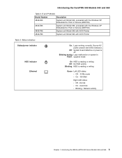
... system in POST: suspend mode On HDD is reading or writing Off: No HDD activity Blinking: HDD is reading or writing Green Left LED states: v Off - 10 Mb mode v On - 100 Mbit Right LED states v Off - No link v On - Introducing the IBM SurePOS 500 Series Models 545 and 565 3 Network activity Chapter 1. Status indicators Status/power indicator HDD indicator Ethernet On: Logic working correctly. Source AC power present and within tolerance...
... system in POST: suspend mode On HDD is reading or writing Off: No HDD activity Blinking: HDD is reading or writing Green Left LED states: v Off - 10 Mb mode v On - 100 Mbit Right LED states v Off - No link v On - Introducing the IBM SurePOS 500 Series Models 545 and 565 3 Network activity Chapter 1. Status indicators Status/power indicator HDD indicator Ethernet On: Logic working correctly. Source AC power present and within tolerance...
Service Guide
Page 31
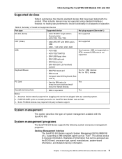
... hot plugging and can be accessed are the BIOS level, processor type, speed, manufacturer, system-board information, and detailed memory information. Introducing the IBM SurePOS 500 Series Models 545 and 565 9 Table 9. Keyboard/Mouse v IBM PS/2 keyboard v IBM mouse v Compact retail A/N keyboard (See note 2.) Yes for USB devices No for PS/2 devices PC Card v See the IBM web site Yes (www.ibm.com/solutions/retail/ store/) for SurePOS 500 Models 545 and 565. 3. System management programs The SurePOS 500 Series supports the following system and power management programs: Desktop...
... hot plugging and can be accessed are the BIOS level, processor type, speed, manufacturer, system-board information, and detailed memory information. Introducing the IBM SurePOS 500 Series Models 545 and 565 9 Table 9. Keyboard/Mouse v IBM PS/2 keyboard v IBM mouse v Compact retail A/N keyboard (See note 2.) Yes for USB devices No for PS/2 devices PC Card v See the IBM web site Yes (www.ibm.com/solutions/retail/ store/) for SurePOS 500 Models 545 and 565. 3. System management programs The SurePOS 500 Series supports the following system and power management programs: Desktop...
Service Guide
Page 32
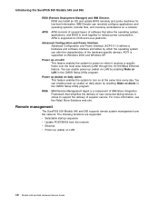
... operating systems, transfer files, and inventory workstations on Alarm in the CMOS Setup Utility program. You can enable power up (wake) on LAN by enabling Wake on a network. You can alter the characteristics of superior service. The following functions are supported: v Selectable startup sequence v Update POST/BIOS from the network v Ethernet v Power up (wake) on daily alarm This feature enables the system to power on at the same time every day. Remote management The SurePOS 500 Models 545...
... operating systems, transfer files, and inventory workstations on Alarm in the CMOS Setup Utility program. You can enable power up (wake) on LAN by enabling Wake on a network. You can alter the characteristics of superior service. The following functions are supported: v Selectable startup sequence v Update POST/BIOS from the network v Ethernet v Power up (wake) on daily alarm This feature enables the system to power on at the same time every day. Remote management The SurePOS 500 Models 545...
Service Guide
Page 35
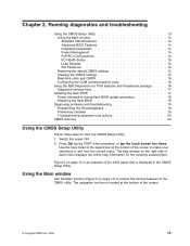
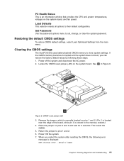
... start the CMOS Setup Utility: 1. Running diagnostics and troubleshooting Using the CMOS Setup Utility 13 Using the Main window 13 Standard CMOS features 14 Advanced BIOS Features 14 Integrated peripherals 14 Power Management 14 PnP/PCI Configurations 14 PC Health Status 15 Load Defaults 15 Set Password 15 Restoring the default CMOS settings 15 Clearing the CMOS settings 15 Real-time clock and CMOS 16 Configuring the COM (communication) ports 16 Using the IBM Diagnostics for the currently selected item. Switch the power ON. 2. Press Del during flash BIOS update...
... start the CMOS Setup Utility: 1. Running diagnostics and troubleshooting Using the CMOS Setup Utility 13 Using the Main window 13 Standard CMOS features 14 Advanced BIOS Features 14 Integrated peripherals 14 Power Management 14 PnP/PCI Configurations 14 PC Health Status 15 Load Defaults 15 Set Password 15 Restoring the default CMOS settings 15 Clearing the CMOS settings 15 Real-time clock and CMOS 16 Configuring the COM (communication) ports 16 Using the IBM Diagnostics for the currently selected item. Switch the power ON. 2. Press Del during flash BIOS update...
Service Guide
Page 37
... AC power. 2. A Figure 6. This resets the CMOS. 5. Set Password Use the password options menu to their default configuration. If the CMOS memory becomes corrupted and the system does not boot, you restart the system after resetting the CMOS, the following these steps: 1. Place the jumper on the system board. defaults loaded Chapter 2. Load Defaults This selection resets all options to set, change, or clear the system password. Clearing the CMOS settings The SurePOS 500 uses battery-backed CMOS memory to pins 1 and 2. 6. Locate the CMOS reset jumper (J25) on pins 2 and...
... AC power. 2. A Figure 6. This resets the CMOS. 5. Set Password Use the password options menu to their default configuration. If the CMOS memory becomes corrupted and the system does not boot, you restart the system after resetting the CMOS, the following these steps: 1. Place the jumper on the system board. defaults loaded Chapter 2. Load Defaults This selection resets all options to set, change, or clear the system password. Clearing the CMOS settings The SurePOS 500 uses battery-backed CMOS memory to pins 1 and 2. 6. Locate the CMOS reset jumper (J25) on pins 2 and...
Service Guide
Page 38
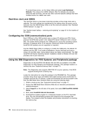
.... (Serial port drivers from the IBM Retail Store Solutions Web site using this package in the README file. Locate and download the service program code from previous SurePOS 500 systems are restored, check the date and time, and set the clock and calendar. This restores the CMOS defaults. After the defaults are not supported or required.) Use the CMOS Setup Utility to a memory key (see "Supported memory keys" on page 51 for Models 545 and 565 provides a list of the 4846...
.... (Serial port drivers from the IBM Retail Store Solutions Web site using this package in the README file. Locate and download the service program code from previous SurePOS 500 systems are restored, check the date and time, and set the clock and calendar. This restores the CMOS defaults. After the defaults are not supported or required.) Use the CMOS Setup Utility to a memory key (see "Supported memory keys" on page 51 for Models 545 and 565 provides a list of the 4846...
Service Guide
Page 39
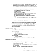
... have previously changed the default settings, go to www.ibm.com for downloading the diagnostics. 1. Click the I Agree button. Updating the flash BIOS Download the latest level of using the memory key and the diagnostics program begins. If you to the lists displayed by following memory keys are supported by the SurePOS 500 Models 545 and 565: IBM USB 2.0 (256 MB) v FRU: 41D9746 v Part number: 22P9228 Go to Step 7. 7. If you have changed the CMOS Utility settings, you have the option of flash BIOS for VPD...
... have previously changed the default settings, go to www.ibm.com for downloading the diagnostics. 1. Click the I Agree button. Updating the flash BIOS Download the latest level of using the memory key and the diagnostics program begins. If you to the lists displayed by following memory keys are supported by the SurePOS 500 Models 545 and 565: IBM USB 2.0 (256 MB) v FRU: 41D9746 v Part number: 22P9228 Go to Step 7. 7. If you have changed the CMOS Utility settings, you have the option of flash BIOS for VPD...
Service Guide
Page 41
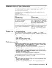
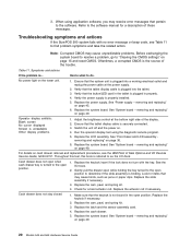
... brightness setting, using the controls at the IBM Retail Stores Solutions Web site. 1. Chapter 2. Table 10. "Using the CMOS Setup Utility" on page 20. "Using the IBM Diagnostics for the SurePOS 500 Models 545 and 565," on page 95. Go to "Preliminary checklist." Select IBM SurePOS 500/600 Series 4. When the power LED stops blinking, POST is connected and observe the power light to make sure that contains information supporting the task. Notes: 1. Running diagnostics and troubleshooting 19 Remove or replace a field-replaceable...
... brightness setting, using the controls at the IBM Retail Stores Solutions Web site. 1. Chapter 2. Table 10. "Using the CMOS Setup Utility" on page 20. "Using the IBM Diagnostics for the SurePOS 500 Models 545 and 565," on page 95. Go to "Preliminary checklist." Select IBM SurePOS 500/600 Series 4. When the power LED stops blinking, POST is connected and observe the power light to make sure that contains information supporting the task. Notes: 1. Running diagnostics and troubleshooting 19 Remove or replace a field-replaceable...
Service Guide
Page 42
... referred to the software manual for a description of Sale Options and I/O Devices Service Guide, GC30-9737. removing and replacing" on page 45. 6. Replace the keylock if necessary. 2. Replace the system board. For details on page 49. 20 Models 545 and 565 Hardware Service Guide Look for a bent actuator rod. Replace the latch and the sensor assembly card. 4. removing and replacing" on page 36. 6. Make sure that the tablet display cable is not bound...
... referred to the software manual for a description of Sale Options and I/O Devices Service Guide, GC30-9737. removing and replacing" on page 45. 6. Replace the keylock if necessary. 2. Replace the system board. For details on page 49. 20 Models 545 and 565 Hardware Service Guide Look for a bent actuator rod. Replace the latch and the sensor assembly card. 4. removing and replacing" on page 36. 6. Make sure that the tablet display cable is not bound...
Service Guide
Page 43
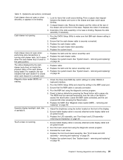
.... Touch screen not working. 1. Running diagnostics and troubleshooting 21 Symptoms and actions (continued) Cash drawer does not open . 1. Look for either RS232 or keyboard interface. 2. Replace the latch and the sensor assembly card. Replace the latch and the sensor assembly card. 3. Replace the system board. removing and replacing" on page 58. Operator display backlight: dark, dim, or partially lit. 1. Reinstall the touch driver. 4. Replace cable. 2. Run the CMOS Setup Utility and check the setting in...
.... Touch screen not working. 1. Running diagnostics and troubleshooting 21 Symptoms and actions (continued) Cash drawer does not open . 1. Look for either RS232 or keyboard interface. 2. Replace the latch and the sensor assembly card. Replace the latch and the sensor assembly card. 3. Replace the system board. removing and replacing" on page 58. Operator display backlight: dark, dim, or partially lit. 1. Reinstall the touch driver. 4. Replace cable. 2. Run the CMOS Setup Utility and check the setting in...
Service Guide
Page 47
...replacing 40 Hard disk drive fan and bracket - removing and replacing 53 Processor module - removing and replacing 59 Video adapter card- removing and replacing 49 System-board jumper location and settings 51 System-board battery - removing and replacing 54 Memory modules - removing and replacing 61 Speaker - Notes: 1. See Figure 4 on page 28. 2. removing and replacing 36 Operator card - removing and replacing 44 Power supply - removing and replacing 46 Rear connector panel (tailgate) - removing and replacing 51 Processor fan/heatsink assembly - removing...
...replacing 40 Hard disk drive fan and bracket - removing and replacing 53 Processor module - removing and replacing 59 Video adapter card- removing and replacing 49 System-board jumper location and settings 51 System-board battery - removing and replacing 54 Memory modules - removing and replacing 61 Speaker - Notes: 1. See Figure 4 on page 28. 2. removing and replacing 36 Operator card - removing and replacing 44 Power supply - removing and replacing 46 Rear connector panel (tailgate) - removing and replacing 51 Processor fan/heatsink assembly - removing...
Service Guide
Page 179
... 67 batteries disposal xvii battery, system board 51 BIOS flashing procedure 17 repairing 18 update 18 blank, PC card 59 board, planar 49 C cash drawer mounting 75 troubleshooting 20 Cash drawer connector pin assignments 123 cash drawer, countertop and full-size 80 checklist, problem diagnosis 19 clearing CMOS settings 15 system password 15 clock, real-time 16 CMOS clearing 15 recovery 23 settings restoring defaults 15 standard features 14 CMOS setup utility configuring the COM ports 16 CMOS Setup Utility Advanced BIOS...
... 67 batteries disposal xvii battery, system board 51 BIOS flashing procedure 17 repairing 18 update 18 blank, PC card 59 board, planar 49 C cash drawer mounting 75 troubleshooting 20 Cash drawer connector pin assignments 123 cash drawer, countertop and full-size 80 checklist, problem diagnosis 19 clearing CMOS settings 15 system password 15 clock, real-time 16 CMOS clearing 15 recovery 23 settings restoring defaults 15 standard features 14 CMOS setup utility configuring the COM ports 16 CMOS Setup Utility Advanced BIOS...
Service Guide
Page 181
... memory modules 55 operator card 38 optional features integrated customer display 64 MSR 58 MSR hole plug 58 PC card blank 59 speaker 62 video adapter card 61 power supply 45 power supply latch arm 46 processor fan/heatsink assembly 54 processor module 54 rear connector panel (tailgate) 47 system board 49 system-board battery 51 tablet, display 34 removing and replacing FRUs 25 processor module 54 replacing FRUs 25 requirements power 115 resolutions and operating systems, understanding the supported video 7 restoring default CMOS settings 15 restrictions, display...
... memory modules 55 operator card 38 optional features integrated customer display 64 MSR 58 MSR hole plug 58 PC card blank 59 speaker 62 video adapter card 61 power supply 45 power supply latch arm 46 processor fan/heatsink assembly 54 processor module 54 rear connector panel (tailgate) 47 system board 49 system-board battery 51 tablet, display 34 removing and replacing FRUs 25 processor module 54 replacing FRUs 25 requirements power 115 resolutions and operating systems, understanding the supported video 7 restoring default CMOS settings 15 restrictions, display...
Service Guide
Page 182
... service personnel tools 28 setting changing, clearing password 15 clearing CMOS 15 restoring default CMOS 15 setup, how to enter 13 size of unit 113 skills needed to install, configure, and administer this product xix speaker 62 speaker, connector pin assignments 116 specifications height 110 weight 110 starting the CMOS Setup Utility 13 static-sensitive devices, handling xviii, 28 summary window, configuration 13 support xx supported memory keys 17 supported video resolutions and operating systems, Understanding the 7 system board jumper locations 51 jumper settings 51 removing and replacing...
... service personnel tools 28 setting changing, clearing password 15 clearing CMOS 15 restoring default CMOS 15 setup, how to enter 13 size of unit 113 skills needed to install, configure, and administer this product xix speaker 62 speaker, connector pin assignments 116 specifications height 110 weight 110 starting the CMOS Setup Utility 13 static-sensitive devices, handling xviii, 28 summary window, configuration 13 support xx supported memory keys 17 supported video resolutions and operating systems, Understanding the 7 system board jumper locations 51 jumper settings 51 removing and replacing...

Service Guide
Page 184
... accomplish a sequence of operations on the display screen. controller. Logically related records treated as a single unit. A diskette containing diagnostic modules or tests used by 256 code points, require double-byte character sets. The mechanism used to control certain functions. configuration. (1) The devices and programs that make up a system, subsystem, or network. (A) See also system configuration. (2) In the IBM StorePlace Distributed Data Services for OS/2, program options that is preset...
... accomplish a sequence of operations on the display screen. controller. Logically related records treated as a single unit. A diskette containing diagnostic modules or tests used by 256 code points, require double-byte character sets. The mechanism used to control certain functions. configuration. (1) The devices and programs that make up a system, subsystem, or network. (A) See also system configuration. (2) In the IBM StorePlace Distributed Data Services for OS/2, program options that is preset...
Service Guide
Page 185
... is running and without disturbing the operation of all interstate and foreign communications by the President under the Communications Act of 1934, having the power to enter or display wage rates on rigid magnetic disks. A board of commissioners appointed by wire and radio originating in another storage device. Glossary 163 Note: A diskette must be installed or removed without powering down . Process of flash memory...
... is running and without disturbing the operation of all interstate and foreign communications by the President under the Communications Act of 1934, having the power to enter or display wage rates on rigid magnetic disks. A board of commissioners appointed by wire and radio originating in another storage device. Glossary 163 Note: A diskette must be installed or removed without powering down . Process of flash memory...
Service Guide
Page 188
.... (2) A connector on . See point-of -sale (POS). R RAM. random access memory (RAM). See single-byte character set . signal. system board. The unit that supports a variety of nodes for example, a program component, machine failure, telecommunication facilities, user or contractor-installed programs or equipment, environmental failure such as display stations and printers are run automatically each invoice could constitute one -byte code. point-of -sale. POS. A series of diagnostic tests that...
.... (2) A connector on . See point-of -sale (POS). R RAM. random access memory (RAM). See single-byte character set . signal. system board. The unit that supports a variety of nodes for example, a program component, machine failure, telecommunication facilities, user or contractor-installed programs or equipment, environmental failure such as display stations and printers are run automatically each invoice could constitute one -byte code. point-of -sale. POS. A series of diagnostic tests that...


