Service Guide
Page 9
...-size keyboard-integration tray on all models 6 4. Removing the rear cover 30 10. Removing the hinge cover 33 13. Disconnecting the touch cable and removing the front bezel 36 16. HDD installation 40 20. Removing the HDD fan and bracket 42 22. Attaching a mounting...top cover release latch 32 12. View of input/output available on a countertop 80 © Copyright IBM Corp. 2006 vii Removing the processor fan/ heatsink assembly 53 31. Figures 1. IBM SurePOS 500 Series configuration with optional features 1 2. Sliding the fence off of the integration tray 72 47. CMOS...
...-size keyboard-integration tray on all models 6 4. Removing the rear cover 30 10. Removing the hinge cover 33 13. Disconnecting the touch cable and removing the front bezel 36 16. HDD installation 40 20. Removing the HDD fan and bracket 42 22. Attaching a mounting...top cover release latch 32 12. View of input/output available on a countertop 80 © Copyright IBM Corp. 2006 vii Removing the processor fan/ heatsink assembly 53 31. Figures 1. IBM SurePOS 500 Series configuration with optional features 1 2. Sliding the fence off of the integration tray 72 47. CMOS...
Service Guide
Page 20
... joints, pins, or exposed printed circuitry. To avoid damage, keep static-sensitive devices in its anti-static bag, touch it to an unpainted metal part of the system or onto a metal table. v Handle the device carefully, holding it as required by its edges or ... where others can damage electronic devices and your device is an adapter, place it is still in their static protective bags until you . xviii Models 545 and 565 Hardware Service Guide Magnetic stripe reader The electronic article surveillance device (EAS) that deactivates security tags should not be closer than 18 in...
... joints, pins, or exposed printed circuitry. To avoid damage, keep static-sensitive devices in its anti-static bag, touch it to an unpainted metal part of the system or onto a metal table. v Handle the device carefully, holding it as required by its edges or ... where others can damage electronic devices and your device is an adapter, place it is still in their static protective bags until you . xviii Models 545 and 565 Hardware Service Guide Magnetic stripe reader The electronic article surveillance device (EAS) that deactivates security tags should not be closer than 18 in...
Service Guide
Page 24
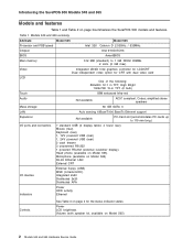
... 565 summary Attribute Model 545 Model 565 Processor and FSB speed Intel 326 Celeron D 2.53GHz / 533MHz Chipset Intel 915GV/ICH6 BIOS AwardBIOS Main memory 512 MB (standard) to 119 mm long.) I/O ports and connectors 7 standard USB (3 display tablet, 4 tower rear) Mouse (rear) Keyboard (rear) 1, ... card LCD One of the following: 800x600 12.1 in TFT, High Bright 1024x768 15-in TFT (2 bulb) Touch IBM enhanced Infra-red Audio Not available AC97 compliant, Codec; Introducing the SurePOS 500 Models 545 and 565 Models and features Table 1 and Table 2 on Model 565) 2 Models...
... 565 summary Attribute Model 545 Model 565 Processor and FSB speed Intel 326 Celeron D 2.53GHz / 533MHz Chipset Intel 915GV/ICH6 BIOS AwardBIOS Main memory 512 MB (standard) to 119 mm long.) I/O ports and connectors 7 standard USB (3 display tablet, 4 tower rear) Mouse (rear) Keyboard (rear) 1, ... card LCD One of the following: 800x600 12.1 in TFT, High Bright 1024x768 15-in TFT (2 bulb) Touch IBM enhanced Infra-red Audio Not available AC97 compliant, Codec; Introducing the SurePOS 500 Models 545 and 565 Models and features Table 1 and Table 2 on Model 565) 2 Models...
Service Guide
Page 27
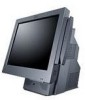
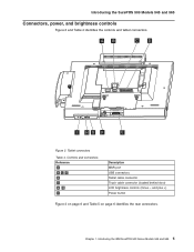
Introducing the SurePOS 500 Models 545 and 565 Connectors, power, and brightness controls Figure 2 and Table 4 identifies the controls and tablet connectors. Introducing the IBM SurePOS 500 Series Models 545 and 565 5 and plus +) Power button Figure 3 on page 6 and Table 5 on page 6 identifies the rear connectors. AB C D I Description MSR port USB connectors Tablet cable connector Touch cable connector (located behind door) LCD brightness controls (minus - Controls and connectors Reference A BCF D E G H I HG F E Figure 2. Tablet connectors Table 4. Chapter 1.
Introducing the SurePOS 500 Models 545 and 565 Connectors, power, and brightness controls Figure 2 and Table 4 identifies the controls and tablet connectors. Introducing the IBM SurePOS 500 Series Models 545 and 565 5 and plus +) Power button Figure 3 on page 6 and Table 5 on page 6 identifies the rear connectors. AB C D I Description MSR port USB connectors Tablet cable connector Touch cable connector (located behind door) LCD brightness controls (minus - Controls and connectors Reference A BCF D E G H I HG F E Figure 2. Tablet connectors Table 4. Chapter 1.
Service Guide
Page 29
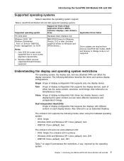
...Also referred to touch screen alignment requirements. 2. Clone A type of Service (WEPOS) Power management via ACPI IBM UPOS Drivers for Windows, Version 1.9.2 or later. (Includes JavaPOS drivers for Windows and OPOS drivers.) Notes: 1. Introducing the IBM SurePOS 500 Series Models 545 and 565 ... same content, but can affect the display resolution. Introducing the SurePOS 500 Models 545 and 565 Supported operating systems Table 6 describes the operating system support: Table 6. SurePOS 500 Models 545 and 565 supported operating systems Supported operating system Support for Point of...
...Also referred to touch screen alignment requirements. 2. Clone A type of Service (WEPOS) Power management via ACPI IBM UPOS Drivers for Windows, Version 1.9.2 or later. (Includes JavaPOS drivers for Windows and OPOS drivers.) Notes: 1. Introducing the IBM SurePOS 500 Series Models 545 and 565 ... same content, but can affect the display resolution. Introducing the SurePOS 500 Models 545 and 565 Supported operating systems Table 6 describes the operating system support: Table 6. SurePOS 500 Models 545 and 565 supported operating systems Supported operating system Support for Point of...
Service Guide
Page 30
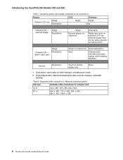
...show on both displays; simultaneous mode 2. different/independent data on onboard LCD only; extended desktop Table 8. Introducing the SurePOS 500 Models 545 and 565 Table 7. Dual-same: same data on primary display only None 1. Supported video resolutions in Windows operating ...video card Image Restrictions Single, on board LCD None Dual-independent₂ Onboard LCD becomes secondary display when installing Windows General Restrictions Touch on both displays; Dual-independent; External display must be the same resolution as onboard LCD Onboard LCD + Add-in . 640...
...show on both displays; simultaneous mode 2. different/independent data on onboard LCD only; extended desktop Table 8. Introducing the SurePOS 500 Models 545 and 565 Table 7. Dual-same: same data on primary display only None 1. Supported video resolutions in Windows operating ...video card Image Restrictions Single, on board LCD None Dual-independent₂ Onboard LCD becomes secondary display when installing Windows General Restrictions Touch on both displays; Dual-independent; External display must be the same resolution as onboard LCD Onboard LCD + Add-in . 640...
Service Guide
Page 35
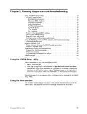
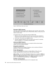
...is an example of the initial panel that is located at the bottom of the screen. © Copyright IBM Corp. 2006 13 Use the keys listed in the CMOS Setup Utility. The navigation tool bar is displayed...Clearing the CMOS settings 15 Real-time clock and CMOS 16 Configuring the COM (communication) ports 16 Using the IBM Diagnostics for the currently selected item. Figure 5 on page 14) to start the CMOS Setup Utility: 1.... the flash BIOS 17 Power interruption during POST when prompted, or tap the touch screen two times. The help window on the right side of the CMOS utility.
...is an example of the initial panel that is located at the bottom of the screen. © Copyright IBM Corp. 2006 13 Use the keys listed in the CMOS Setup Utility. The navigation tool bar is displayed...Clearing the CMOS settings 15 Real-time clock and CMOS 16 Configuring the COM (communication) ports 16 Using the IBM Diagnostics for the currently selected item. Figure 5 on page 14) to start the CMOS Setup Utility: 1.... the flash BIOS 17 Power interruption during POST when prompted, or tap the touch screen two times. The help window on the right side of the CMOS utility.
Service Guide
Page 36
... Power Management Setup menu to configure Wake on Ring feature. Additionally, the tailgate card contains jumpers for PCI configuration data. 14 Models 545 and 565 Hardware Service Guide PnP/PCI Configurations This option allows advanced functions for ports A-C to optionally associate DSR (pin 1) to ... the date, month, and time using Ring Indicate. It also provides basic information, such as text. 3. For example, enter 8 to Ring Indicate. Touch enter. For example, enter 8 for August, or 1 for January, and select Enter. Using the displayed keyboard, enter the number of the month. ...
... Power Management Setup menu to configure Wake on Ring feature. Additionally, the tailgate card contains jumpers for PCI configuration data. 14 Models 545 and 565 Hardware Service Guide PnP/PCI Configurations This option allows advanced functions for ports A-C to optionally associate DSR (pin 1) to ... the date, month, and time using Ring Indicate. It also provides basic information, such as text. 3. For example, enter 8 to Ring Indicate. Touch enter. For example, enter 8 for August, or 1 for January, and select Enter. Using the displayed keyboard, enter the number of the month. ...
Service Guide
Page 43
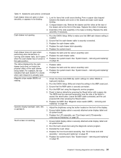
...running cash drawer tests, but it opens 2. Replace the cash drawer cable. when the cash drawer key is turned to make sure that IBM cash drawer setting is enabled. 2. For example, the test indicates that could cause binding. 2. Replace cable. 2. Replace the system board...that cash drawer A is closed when cash drawer A is securely connected. 4. Adjust the brightness using the diagnostic service program. 3. Reinstall the touch driver. 4. Replace the system board. Cash drawer does not open position. Replace the latch and the sensor assembly card. See "System board -...
...running cash drawer tests, but it opens 2. Replace the cash drawer cable. when the cash drawer key is turned to make sure that IBM cash drawer setting is enabled. 2. For example, the test indicates that could cause binding. 2. Replace cable. 2. Replace the system board...that cash drawer A is closed when cash drawer A is securely connected. 4. Adjust the brightness using the diagnostic service program. 3. Reinstall the touch driver. 4. Replace the system board. Cash drawer does not open position. Replace the latch and the sensor assembly card. See "System board -...
Service Guide
Page 48
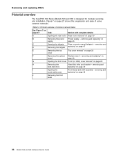
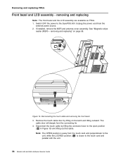
... the front bezel 26 Models 545 and 565 Hardware Service Guide removing and touch-cable cover replacing" on page 40 I Opening the "Front bezel and LCD assembly - removing and replacing" on page 32 cover F Removing the system "System board - Removing and replacing FRUs Pictorial overview The SurePOS 500 Series Models 545 and 565 is designed...
... the front bezel 26 Models 545 and 565 Hardware Service Guide removing and touch-cable cover replacing" on page 40 I Opening the "Front bezel and LCD assembly - removing and replacing" on page 32 cover F Removing the system "System board - Removing and replacing FRUs Pictorial overview The SurePOS 500 Series Models 545 and 565 is designed...
Service Guide
Page 50
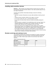
... bag, touch it and your finger to an unpainted metal part of electrostatic discharge, observe the following precautions: v Limit your system. v Do not leave the device where others can cause static electricity to install them. Modular servicing and minimum tools The SurePOS 500 Models 545 and 565...in their static protective bags until you may require a tool. v Do not touch solder joints, pins, or exposed printed circuitry. If it is necessary to 9-pin 40N5341 conversion Units 1 1 1 28 Models 545 and 565 Hardware Service Guide v Take additional care when handling devices during cold ...
... bag, touch it and your finger to an unpainted metal part of electrostatic discharge, observe the following precautions: v Limit your system. v Do not leave the device where others can cause static electricity to install them. Modular servicing and minimum tools The SurePOS 500 Models 545 and 565...in their static protective bags until you may require a tool. v Do not touch solder joints, pins, or exposed printed circuitry. If it is necessary to 9-pin 40N5341 conversion Units 1 1 1 28 Models 545 and 565 Hardware Service Guide v Take additional care when handling devices during cold ...
Service Guide
Page 58
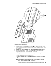
...FRUs. 1. Unplug the power cord from the touch card and perpendicular to the touch card and parallel with the unit. 36 Models 545 and 565 Hardware Service Guide Disconnecting the touch cable and removing the front bezel 3. Disconnect the touch cable by lifting on page 58. See "...- Removing and replacing FRUs Front bezel and LCD assembly - removing and replacing" on the latch and lifting outward. Remove the touch cable door by lifting the connector lever to the SurePOS 500. V O L Figure 15. Note: The OPEN position is closer to the unit, while the LOCKED position ( L ...
...FRUs. 1. Unplug the power cord from the touch card and perpendicular to the touch card and parallel with the unit. 36 Models 545 and 565 Hardware Service Guide Disconnecting the touch cable and removing the front bezel 3. Disconnect the touch cable by lifting on page 58. See "...- Removing and replacing FRUs Front bezel and LCD assembly - removing and replacing" on the latch and lifting outward. Remove the touch cable door by lifting the connector lever to the SurePOS 500. V O L Figure 15. Note: The OPEN position is closer to the unit, while the LOCKED position ( L ...
Service Guide
Page 59
...in Figure 15 on page 36). Continue to unlock the bezel, and lift upward until the bezel stops. Removing and replacing FRUs for the SurePOS 500 Models 545 and 565 37 Press the buttons on page 36. To replace the front bezel or LCD assembly from the tablet. 6. Chapter 3. Ensure ...that the connector lever is in Figure 16. b. c. Then pull the bezel away from the front bezel assembly, reverse these procedures and reconnect the touch cable:...
...in Figure 15 on page 36). Continue to unlock the bezel, and lift upward until the bezel stops. Removing and replacing FRUs for the SurePOS 500 Models 545 and 565 37 Press the buttons on page 36. To replace the front bezel or LCD assembly from the tablet. 6. Chapter 3. Ensure ...that the connector lever is in Figure 16. b. c. Then pull the bezel away from the front bezel assembly, reverse these procedures and reconnect the touch cable:...
Service Guide
Page 71
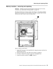
removing and replacing Attention: Establish personal grounding before touching this unit. Remove the power supply as described in "Rear cover removal" on page 45 4. Figure 27. Follow the steps described in "Power supply - Grasp ... 27. Chapter 3. Unplug the power cord from the external power source. 2. Removing and replacing FRUs for the SurePOS 500 Models 545 and 565 49 removing and replacing" on page 130. Switch OFF the power to the SurePOS 500. Disconnect the cables and remove the I/O tailgate cover as shown in "Rear connector panel (tailgate) - Removing the...
removing and replacing Attention: Establish personal grounding before touching this unit. Remove the power supply as described in "Rear cover removal" on page 45 4. Figure 27. Follow the steps described in "Power supply - Grasp ... 27. Chapter 3. Unplug the power cord from the external power source. 2. Removing and replacing FRUs for the SurePOS 500 Models 545 and 565 49 removing and replacing" on page 130. Switch OFF the power to the SurePOS 500. Disconnect the cables and remove the I/O tailgate cover as shown in "Rear connector panel (tailgate) - Removing the...
Service Guide
Page 76
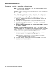
...OFF the power to use the section cup tool provided with the FRU processor. 5. Attention: Establish personal grounding before touching this unit. Attention: The SurePOS Models 545 and 565 contain a LGA 775 CPU socket. Release the latch and carefully remove the processor from the external power ...panel (tailgate) - Removing and replacing FRUs Processor module - Note: Examine the thermal interface on page 30. 3. Be sure to the SurePOS 500. See "Electrostatic Discharge (ESD)" on page 47. The LGA 775 CPU socket contains very finely pitched pins. Unplug the power cord from ...
...OFF the power to use the section cup tool provided with the FRU processor. 5. Attention: Establish personal grounding before touching this unit. Attention: The SurePOS Models 545 and 565 contain a LGA 775 CPU socket. Release the latch and carefully remove the processor from the external power ...panel (tailgate) - Removing and replacing FRUs Processor module - Note: Examine the thermal interface on page 30. 3. Be sure to the SurePOS 500. See "Electrostatic Discharge (ESD)" on page 47. The LGA 775 CPU socket contains very finely pitched pins. Unplug the power cord from ...
Service Guide
Page 77
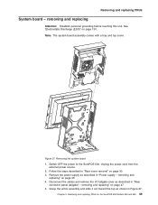
.... 4. See Figure 31. A Figure 31. Switch OFF the power to the SurePOS 500. Remove the back cover. As shown in Figure 31. Removing and replacing FRUs for the SurePOS 500 Models 545 and 565 55 removing and replacing Attention: Establish personal grounding before touching this unit. See A in Figure 25 on page 30. 3. All system boards...
.... 4. See Figure 31. A Figure 31. Switch OFF the power to the SurePOS 500. Remove the back cover. As shown in Figure 31. Removing and replacing FRUs for the SurePOS 500 Models 545 and 565 55 removing and replacing Attention: Establish personal grounding before touching this unit. See A in Figure 25 on page 30. 3. All system boards...
Service Guide
Page 78
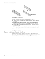
... does not work with every product, IBM performs extensive life and reliability testing to insure that memory offered by IBM Retail for use memory provided by IBM will operate correctly over all voltage and temperature ranges. 56 Models 545 and 565 Hardware Service Guide Replace the... I/O tailgate cover. 10. Press the latches away from the socket. 7. Removing and replacing FRUs Retainer Figure 32. Memory module removal 5. cass1eco 8. Touching only...
... does not work with every product, IBM performs extensive life and reliability testing to insure that memory offered by IBM Retail for use memory provided by IBM will operate correctly over all voltage and temperature ranges. 56 Models 545 and 565 Hardware Service Guide Replace the... I/O tailgate cover. 10. Press the latches away from the socket. 7. Removing and replacing FRUs Retainer Figure 32. Memory module removal 5. cass1eco 8. Touching only...
Service Guide
Page 91
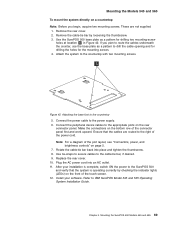
...IBM SurePOS Model 545 and 565 Operating System Installation Guide. Make the connections on page 5. 7. Note: For a diagram of the touch screen. 12. Install your installation is complete, switch ON the power to the power supply. 6. Rotate the cable-tie bar back into an AC outlet. 11. Mounting the SurePOS 500 Models 545...-screw holes at location S in Figure 42. Mounting the Models 545 and 565 To mount the system directly on the rear connector panel. After your software. Connect the power cable to the SurePOS 500 and verify that the cables are not supplied. 1.
...IBM SurePOS Model 545 and 565 Operating System Installation Guide. Make the connections on page 5. 7. Note: For a diagram of the touch screen. 12. Install your installation is complete, switch ON the power to the power supply. 6. Rotate the cable-tie bar back into an AC outlet. 11. Mounting the SurePOS 500 Models 545...-screw holes at location S in Figure 42. Mounting the Models 545 and 565 To mount the system directly on the rear connector panel. After your software. Connect the power cable to the SurePOS 500 and verify that the cables are not supplied. 1.
Service Guide
Page 97
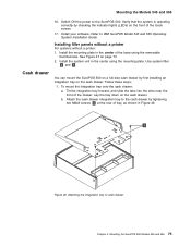
... Use system filler G and K . Attaching the integration tray to IBM SurePOS Model 545 and 565 Operating System Installation Guide. Verify that the system is operating...touch screen. 17. A Figure 49. To mount the integration tray onto the cash drawer: a. See Figure 47 on the front of the base using the mounting plate. Follow these steps: 1. Refer to cash drawer Chapter 4. Cash drawer You can mount the SurePOS 500...Figure 49. Attach the cash drawer integration tray to the SurePOS 500. Mounting the SurePOS 500 Models 545 and 565 75 Switch ON the power to the cash ...
... Use system filler G and K . Attaching the integration tray to IBM SurePOS Model 545 and 565 Operating System Installation Guide. Verify that the system is operating...touch screen. 17. A Figure 49. To mount the integration tray onto the cash drawer: a. See Figure 47 on the front of the base using the mounting plate. Follow these steps: 1. Refer to cash drawer Chapter 4. Cash drawer You can mount the SurePOS 500...Figure 49. Attach the cash drawer integration tray to the SurePOS 500. Mounting the SurePOS 500 Models 545 and 565 75 Switch ON the power to the cash ...
Service Guide
Page 110
Mounting the Models 545 and 565 22. Switch ON the power and verify that the system is operating correctly by checking the indicator lights (LEDs) on the front of the touch screen. 23. Install your software. Refer to IBM SurePOS Model 545 and 565 Operating System Installation Guide. 88 Models 545 and 565 Hardware Service Guide
Mounting the Models 545 and 565 22. Switch ON the power and verify that the system is operating correctly by checking the indicator lights (LEDs) on the front of the touch screen. 23. Install your software. Refer to IBM SurePOS Model 545 and 565 Operating System Installation Guide. 88 Models 545 and 565 Hardware Service Guide

