
User Guide
Page 9
... switch 9 Installing the switch into an EIA cabinet . . . . . 9 Time required 10 Items required 10 Installation instructions 10 Recommendations for the SAN26B-4 Express . . Product specifications . . . 33 Weight and physical dimensions 33 Environmental requirements 33 Facility requirements 34 System...switch 16 Using the EZSwitch setup (optional) . . . . . 16 Providing power to the switch 16 © Copyright IBM Corp. 2008, 2010 Creating a serial connection 17 Setting the switch IP address 17 Setting the date and time 18 Chapter 3. Operating the switch . . . . 21 Powering the switch...
... switch 9 Installing the switch into an EIA cabinet . . . . . 9 Time required 10 Items required 10 Installation instructions 10 Recommendations for the SAN26B-4 Express . . Product specifications . . . 33 Weight and physical dimensions 33 Environmental requirements 33 Facility requirements 34 System...switch 16 Using the EZSwitch setup (optional) . . . . . 16 Providing power to the switch 16 © Copyright IBM Corp. 2008, 2010 Creating a serial connection 17 Setting the switch IP address 17 Setting the date and time 18 Chapter 3. Operating the switch . . . . 21 Powering the switch...

User Guide
Page 13
... requirements 33 11. Data transmission ranges 36 15. Ethernet LED patterns 25 8. General specifications 35 13. Switch power supply specifications . . . . 36 © Copyright IBM Corp. 2008, 2010 xi Memory specifications 35 14. Tables 1. Parts supplied with the rack-mount kit ... LED patterns during normal operation 24 7. Physical dimensions and weight of the switch 33 10. Sample caution notices xviii 3. System status LED patterns, status, and recommended actions 23 6. Management options for the switch . . . . 30 9. Facility requirements 34 12.
... requirements 33 11. Data transmission ranges 36 15. Ethernet LED patterns 25 8. General specifications 35 13. Switch power supply specifications . . . . 36 © Copyright IBM Corp. 2008, 2010 xi Memory specifications 35 14. Tables 1. Parts supplied with the rack-mount kit ... LED patterns during normal operation 24 7. Physical dimensions and weight of the switch 33 10. Sample caution notices xviii 3. System status LED patterns, status, and recommended actions 23 6. Management options for the switch . . . . 30 9. Facility requirements 34 12.

User Guide
Page 17
...electrical condition. DANGER To prevent a possible shock from touching two surfaces with your system electrical requirements do not touch the shell until you have completed the voltage and grounding checks. ...To avoid these hazards, ensure that your device or the power rating label for more detailed descriptions and examples of the danger, caution, and attention... and a shock hazard under certain conditions. If any of the conditions are listed below in IBM documents. The following danger notices before proceeding. (D003) About this device. Refer to the ...
...electrical condition. DANGER To prevent a possible shock from touching two surfaces with your system electrical requirements do not touch the shell until you have completed the voltage and grounding checks. ...To avoid these hazards, ensure that your device or the power rating label for more detailed descriptions and examples of the danger, caution, and attention... and a shock hazard under certain conditions. If any of the conditions are listed below in IBM documents. The following danger notices before proceeding. (D003) About this device. Refer to the ...

User Guide
Page 19
... the attached power cords, telecommunications systems, networks, and modems before you open or service any other product. Ensure that will be accompanied by different symbols, as described below : About this unit only with multiple power cords. Turn off everything (unless instructed otherwise). 2. v When possible, use the IBM provided power cord for any power supply assembly. Attach...
... the attached power cords, telecommunications systems, networks, and modems before you open or service any other product. Ensure that will be accompanied by different symbols, as described below : About this unit only with multiple power cords. Turn off everything (unless instructed otherwise). 2. v When possible, use the IBM provided power cord for any power supply assembly. Attach...

User Guide
Page 20
A generally hazardous condition not represented by the U. Read and comply with a 3-wire (two conductors and ground) power cable and plug. CAUTION: Energy hazard present. Shorting may result in the product. Use care when lifting, removing, or installing ...). The weight range of a laser in system outage and possible physical injury. Laser symbols are always accompanied by trained service personnel only. (C032) xviii SAN24B-4 Express Installation, Service, and User Guide Remove all metallic jewelry before installing or servicing this power cable with less severity than 18 kg ...
A generally hazardous condition not represented by the U. Read and comply with a 3-wire (two conductors and ground) power cable and plug. CAUTION: Energy hazard present. Shorting may result in the product. Use care when lifting, removing, or installing ...). The weight range of a laser in system outage and possible physical injury. Laser symbols are always accompanied by trained service personnel only. (C032) xviii SAN24B-4 Express Installation, Service, and User Guide Remove all metallic jewelry before installing or servicing this power cable with less severity than 18 kg ...

User Guide
Page 21
...About this label. (L001) DANGER Rack-mounted devices are not to be used as a shelf or work space. (L002) DANGER Multiple power cords. The actual product safety labels may accompany an attention notice, but is not required. Tie wraps are often installed directly on products..., which can be either danger or caution notices, depending upon the level of damage to a program, device, or system, or to data. To remove all hazardous voltages, disconnect all power cords. (L003) DANGER Hazardous voltage present. you can damage the cable. A sample attention notice follows: Attention: Do...
...About this label. (L001) DANGER Rack-mounted devices are not to be used as a shelf or work space. (L002) DANGER Multiple power cords. The actual product safety labels may accompany an attention notice, but is not required. Tie wraps are often installed directly on products..., which can be either danger or caution notices, depending upon the level of damage to a program, device, or system, or to data. To remove all hazardous voltages, disconnect all power cords. (L003) DANGER Hazardous voltage present. you can damage the cable. A sample attention notice follows: Attention: Do...
User Guide
Page 22
... be given to the connection of the equipment to fall out of the rack. (R001 part 2 of 2) xx SAN24B-4 Express Installation, Service, and User Guide To provide the correct power connection to a rack, refer to the rating labels located on the equipment in one drawer at a time. v ...This drawer is not correctly wired could place hazardous voltage on the metal parts of the system or the devices that attach to power devices installed in a rack cabinet to the system. Do not plug a power cord from the bottom of rack-mounted devices. Always install servers and optional devices starting ...
... be given to the connection of the equipment to fall out of the rack. (R001 part 2 of 2) xx SAN24B-4 Express Installation, Service, and User Guide To provide the correct power connection to a rack, refer to the rating labels located on the equipment in one drawer at a time. v ...This drawer is not correctly wired could place hazardous voltage on the metal parts of the system or the devices that attach to power devices installed in a rack cabinet to the system. Do not plug a power cord from the bottom of rack-mounted devices. Always install servers and optional devices starting ...
User Guide
Page 25
..." on the Fabric Operating System (Fabric OS) and is compatible with other IBM switches, which allows continued operation with IBM System Storage SAN switch models, 1, 2, 4 and 8 Gbps auto-sensing capability, as well as the SAN grows. v One built-in fixed power unit (not field-replaceable)...NPIV) access gateway. v On-demand scaling of switches to 24 8 Gbit/sec ports v ASIC technology supporting 1, 2, 4 and 8Gbit/sec auto-sensing Fibre Channel ports. Chapter 1. Introducing the SAN24B-4 Express switch The IBM System Storage SAN24B-4 Express is cooled by a redundant fan configuration...
..." on the Fabric Operating System (Fabric OS) and is compatible with other IBM switches, which allows continued operation with IBM System Storage SAN switch models, 1, 2, 4 and 8 Gbps auto-sensing capability, as well as the SAN grows. v One built-in fixed power unit (not field-replaceable)...NPIV) access gateway. v On-demand scaling of switches to 24 8 Gbit/sec ports v ASIC technology supporting 1, 2, 4 and 8Gbit/sec auto-sensing Fibre Channel ports. Chapter 1. Introducing the SAN24B-4 Express switch The IBM System Storage SAN24B-4 Express is cooled by a redundant fan configuration...
User Guide
Page 26
...Light emitting diodes (LEDs) to the most efficient available path in the interoperability matrices at the following web site: www.ibm.com/servers/storage/support/san. Port side of the switch Figure 1 shows the port side of up to the port side. All LEDs are on page 21. 1 2 ...Channel Ports (24) AC power receptacle Port side of the switch Item number 1 2 3 4 5 6 7 2 SAN24B-4 Express Installation, Service, and User Guide Description System status (top) and power (bottom) LEDs System RS232 console port (RJ-45) Ethernet Port with a speed of the switch. v Adaptive Networking Services ...
...Light emitting diodes (LEDs) to the most efficient available path in the interoperability matrices at the following web site: www.ibm.com/servers/storage/support/san. Port side of the switch Figure 1 shows the port side of up to the port side. All LEDs are on page 21. 1 2 ...Channel Ports (24) AC power receptacle Port side of the switch Item number 1 2 3 4 5 6 7 2 SAN24B-4 Express Installation, Service, and User Guide Description System status (top) and power (bottom) LEDs System RS232 console port (RJ-45) Ethernet Port with a speed of the switch. v Adaptive Networking Services ...

User Guide
Page 31
... operation. One grounded 1.8 m (6 ft.) country-specific power cord - IBM System Storage SAN24B-4 Installation, Service, and User Guide (this publication are for cable management" on page 15 v "Configuring the switch" on page 16 Items included with the switch" v "Installation and safety considerations" on page 8 v "Installing a stand-alone switch" on page 9 v "Installing the switch into a slide-rail rack, you mount the...
... operation. One grounded 1.8 m (6 ft.) country-specific power cord - IBM System Storage SAN24B-4 Installation, Service, and User Guide (this publication are for cable management" on page 15 v "Configuring the switch" on page 16 Items included with the switch" v "Installation and safety considerations" on page 8 v "Installing a stand-alone switch" on page 9 v "Installing the switch into a slide-rail rack, you mount the...

User Guide
Page 32
... such a rack. For successful installation and operation of the switch, ensure that the rack into a slide-rail rack, you install the switch with local electrical codes. If it is available to be a standard EIA cabinet. 8 SAN24B-4 Express Installation, Service, and User Guide v The power supply standards provided in the same direction to prepare your...
... such a rack. For successful installation and operation of the switch, ensure that the rack into a slide-rail rack, you install the switch with local electrical codes. If it is available to be a standard EIA cabinet. 8 SAN24B-4 Express Installation, Service, and User Guide v The power supply standards provided in the same direction to prepare your...
User Guide
Page 33
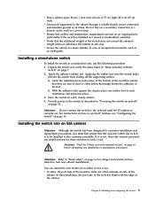
...notices" on a flat, sturdy surface. 4. Unpack the switch and verify the items listed in "Items included with the edge of the switch is also customer accessible. Provide power to set . For instructions on how to the switch as a power strip. v Verify that might lessen the adhesion of the... for danger and caution notices related to a branch circuit, such as described in "Powering the switch on and off the supporting surface. Installing and configuring the switch 9 Attention: Do not connect the switch to "Rack safety" on page 16. Attention: Refer to the network until the ...
...notices" on a flat, sturdy surface. 4. Unpack the switch and verify the items listed in "Items included with the edge of the switch is also customer accessible. Provide power to set . For instructions on how to the switch as a power strip. v Verify that might lessen the adhesion of the... for danger and caution notices related to a branch circuit, such as described in "Powering the switch on and off the supporting surface. Installing and configuring the switch 9 Attention: Do not connect the switch to "Rack safety" on page 16. Attention: Refer to the network until the ...

User Guide
Page 34
.... Be sure to install the switch in a slide-rail rack: v Straight slot screwdriver v Rack space: 1 EIA unit of rack space, 48.3 cm (19 in.) wide, and 60.96 cm (24 in.) deep v One power cord that are listed in Table 3 on page 11. 10 SAN24B-4 Express Installation, Service, and User Guide ...The number keys, such as 1 , refer to slide out the cool-air side of the cabinet. Note: These procedures use the following items to use with the switch v One power outlet v Rack mount kit Attention: Use the ...
.... Be sure to install the switch in a slide-rail rack: v Straight slot screwdriver v Rack space: 1 EIA unit of rack space, 48.3 cm (19 in.) wide, and 60.96 cm (24 in.) deep v One power cord that are listed in Table 3 on page 11. 10 SAN24B-4 Express Installation, Service, and User Guide ...The number keys, such as 1 , refer to slide out the cool-air side of the cabinet. Note: These procedures use the following items to use with the switch v One power outlet v Rack mount kit Attention: Use the ...
User Guide
Page 40
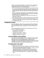
.... If you do not want to boot and complete POST. 16 SAN24B-4 Express Installation, Service, and User Guide Configuring the switch You must meet specific requirements, as a stand-alone switch, it power and a basic configuration. Connect the power cord to the power receptacle on page 18 Using the EZSwitch setup (optional) Once you can use the...
.... If you do not want to boot and complete POST. 16 SAN24B-4 Express Installation, Service, and User Guide Configuring the switch You must meet specific requirements, as a stand-alone switch, it power and a basic configuration. Connect the power cord to the power receptacle on page 18 Using the EZSwitch setup (optional) Once you can use the...

User Guide
Page 41
...connection to set the IP address of the switch are going to set the Ethernet IP address. 2. Setting a static IP address 1. DHCP is password. 2. If you can only connect to the a DHCP server that is complete, verify that the switch power and status LEDs on the left of ...the port side of the switch. Chapter 2. Creating a serial connection You will perform all basic configuration tasks in dotted decimal notation as prompted...
...connection to set the IP address of the switch are going to set the Ethernet IP address. 2. Setting a static IP address 1. DHCP is password. 2. If you can only connect to the a DHCP server that is complete, verify that the switch power and status LEDs on the left of ...the port side of the switch. Chapter 2. Creating a serial connection You will perform all basic configuration tasks in dotted decimal notation as prompted...
User Guide
Page 45
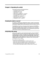
The SAN24B-4 does not have an AC power switch. There are complete. This is powered on the switch. To end the flow of the LEDs on , reset, or rebooted, and requires a minimum of three minutes to run. Interpreting LED activity System activity and status can be determined through the activity of power to a power source. All LEDs are located...
The SAN24B-4 does not have an AC power switch. There are complete. This is powered on the switch. To end the flow of the LEDs on , reset, or rebooted, and requires a minimum of three minutes to run. Interpreting LED activity System activity and status can be determined through the activity of power to a power source. All LEDs are located...

User Guide
Page 46
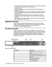
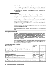
Figure 8 shows the location of LEDs on the port side. B24_0003 LED locations All the switch LEDs are located on the switch Item A B C D E F F E LED names and descriptions System power LED (green) System status LED (green/amber) Ethernet link status LED Ethernet link speed LED Port status LED for port 3 Port status LED for port 7 22 SAN24B-4 Express Installation, Service, and User Guide Detailed view, location of individual LEDs A B C D Figure 8.
Figure 8 shows the location of LEDs on the port side. B24_0003 LED locations All the switch LEDs are located on the switch Item A B C D E F F E LED names and descriptions System power LED (green) System status LED (green/amber) Ethernet link status LED Ethernet link speed LED Port status LED for port 3 Port status LED for port 7 22 SAN24B-4 Express Installation, Service, and User Guide Detailed view, location of individual LEDs A B C D Figure 8.

User Guide
Page 47
... LED patterns, status, and recommended actions LED name LED color Recommended Status of hardware action System Status LED No light Switch is off 1 second) One or both of hardware action Power Status LED No light Primary power cord Verify that switch is on and has failed. Slow-flashing green (on 1 second, off , boot is Verify...
... LED patterns, status, and recommended actions LED name LED color Recommended Status of hardware action System Status LED No light Switch is off 1 second) One or both of hardware action Power Status LED No light Primary power cord Verify that switch is on and has failed. Slow-flashing green (on 1 second, off , boot is Verify...

User Guide
Page 50
Verify that the switch prompt displays on page 8, are met. contact IBM Service for errors. it click into the lower row of ports is with the gold edge down. Ensure that the environmental conditions, described in Figure 9 ... until you use the switchShow command to the system log, which is not successful, the switch did not successfully complete POST; then close the bail. 26 SAN24B-4 Express Installation, Service, and User Guide Interpreting POST results POST is a system check that is performed each time the switch is powered on page 25 for the description and...
Verify that the switch prompt displays on page 8, are met. contact IBM Service for errors. it click into the lower row of ports is with the gold edge down. Ensure that the environmental conditions, described in Figure 9 ... until you use the switchShow command to the system log, which is not successful, the switch did not successfully complete POST; then close the bail. 26 SAN24B-4 Express Installation, Service, and User Guide Interpreting POST results POST is a system check that is performed each time the switch is powered on page 25 for the description and...
User Guide
Page 54
... does reappear, the cable is turned on your switch, refer to the Fabric OS Administrator's Guide. The switch automatically performs power-on page 25. For information about specific diagnostic ...cable and discard the original cable. 12. Management options for a serial connection to accelerate system debugging. Fabric Manager (optional purchase) For information, refer to two admin sessions and four...SAN24B-4 Express Installation, Service, and User Guide The tests are implemented by external cables, to allow diagnostics to verify that the problem does not reappear. Managing the switch ...
... does reappear, the cable is turned on your switch, refer to the Fabric OS Administrator's Guide. The switch automatically performs power-on page 25. For information about specific diagnostic ...cable and discard the original cable. 12. Management options for a serial connection to accelerate system debugging. Fabric Manager (optional purchase) For information, refer to two admin sessions and four...SAN24B-4 Express Installation, Service, and User Guide The tests are implemented by external cables, to allow diagnostics to verify that the problem does not reappear. Managing the switch ...
