
Owners Manual
Page 3
... 13 General Maintenance 14 Transport 16 Controls 17 Control Locations 17 Steering Control Levers 18 Parking Brake 19 Throttle Control 19 Blade Switch 19 Ignition Switch 20 Choke Control 20 Fuses 20 Fuel Tank 21 Fuel Shut Off Valve 22 Cutting Height Adjuster 22 Seat Adjustment Lever 23 ...36 Safety System 37 Fuel Pump Air Filter 37 Tire Pressures 38 Parking Brake 38 V-belts 39 Deck Belt 39 Cutting Blades 40 Blade replacement 40 Adjusting the Mower Deck 41 Leveling deck 41 Anti-scalp Rollers 42 Caster Wheels 43 Cleaning 43 Hardware 43 LUBRICATION 44 Front Wheel Mount...
... 13 General Maintenance 14 Transport 16 Controls 17 Control Locations 17 Steering Control Levers 18 Parking Brake 19 Throttle Control 19 Blade Switch 19 Ignition Switch 20 Choke Control 20 Fuses 20 Fuel Tank 21 Fuel Shut Off Valve 22 Cutting Height Adjuster 22 Seat Adjustment Lever 23 ...36 Safety System 37 Fuel Pump Air Filter 37 Tire Pressures 38 Parking Brake 38 V-belts 39 Deck Belt 39 Cutting Blades 40 Blade replacement 40 Adjusting the Mower Deck 41 Leveling deck 41 Anti-scalp Rollers 42 Caster Wheels 43 Cleaning 43 Hardware 43 LUBRICATION 44 Front Wheel Mount...
Owners Manual
Page 17
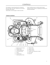
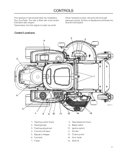
...shut off valve 5. Deck lift 17 Steering control levers 2. Parking brake 3. Fuel tank cap 7. Blade switch 9. Using the left and right steering controls, the flow is fitted with a four-stroke overhead valve engine. Fuses 6. Ignition switch 10. driven hydraulic pumps.... Throttle control 11. Transmission from the engine is made via a belt- Control Locations 4 3 2 1 5 6 7 8 9 10 11 12 13 1. Tracking adjustment 4. Hour meter 13. CONTROLS This operator's manual describes the Husqvarna Zero Turn Rider. ...
...shut off valve 5. Deck lift 17 Steering control levers 2. Parking brake 3. Fuel tank cap 7. Blade switch 9. Using the left and right steering controls, the flow is fitted with a four-stroke overhead valve engine. Fuses 6. Ignition switch 10. driven hydraulic pumps.... Throttle control 11. Transmission from the engine is made via a belt- Control Locations 4 3 2 1 5 6 7 8 9 10 11 12 13 1. Tracking adjustment 4. Hour meter 13. CONTROLS This operator's manual describes the Husqvarna Zero Turn Rider. ...
Owners Manual
Page 19
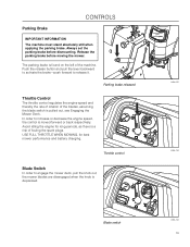
... mower performance and battery charging. Push the release button and pull the lever backward to activate the brake-push forward to engage the mower deck, pull the knob out; The parking brake is moved forward or back respectively. Parking brake released Throttle Control The throttle control regulates the ...engine speed and thereby the rate of rotation of the blades, assuming the blade switch is depressed. 8058-020 8058-134 Blade switch 8058-134 19 In order to increase or decrease the engine speed, the control is found on the left of ...
... mower performance and battery charging. Push the release button and pull the lever backward to activate the brake-push forward to engage the mower deck, pull the knob out; The parking brake is moved forward or back respectively. Parking brake released Throttle Control The throttle control regulates the ...engine speed and thereby the rate of rotation of the blades, assuming the blade switch is depressed. 8058-020 8058-134 Blade switch 8058-134 19 In order to increase or decrease the engine speed, the control is found on the left of ...
Owners Manual
Page 20
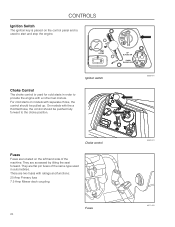
... hand side of the same type used to provide the engine with ratings and functions: 20 Amp Primary fuse 7.5 Amp Mower deck coupling Fuses 20 8052-001 8052-001 8011-420 CONTROLS Ignition Switch The ignition key is placed on the control panel and is used for cold starts in automobiles. Ignition...
... hand side of the same type used to provide the engine with ratings and functions: 20 Amp Primary fuse 7.5 Amp Mower deck coupling Fuses 20 8052-001 8052-001 8011-420 CONTROLS Ignition Switch The ignition key is placed on the control panel and is used for cold starts in automobiles. Ignition...
Owners Manual
Page 25
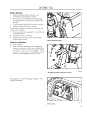
...seat to activate. Pull the lifting lever backward to the locked (transport) position. • Activate the parking brake by pressing the blade switch downwards. 8058-020 Blade switch 8058-134 25 operation Before Starting • Read the sections Safety Instructions and Controls before starting the machine. • Perform the daily ...; The parking brake must be on the top of the lifting lever. Starting the Engine • Sit on the seat. • Raise the mower deck by pushing the release button on . • Both steering controls must be in the locked (outer) neutral position.
...seat to activate. Pull the lifting lever backward to the locked (transport) position. • Activate the parking brake by pressing the blade switch downwards. 8058-020 Blade switch 8058-134 25 operation Before Starting • Read the sections Safety Instructions and Controls before starting the machine. • Perform the daily ...; The parking brake must be on the top of the lifting lever. Starting the Engine • Sit on the seat. • Raise the mower deck by pushing the release button on . • Both steering controls must be in the locked (outer) neutral position.
Owners Manual
Page 29
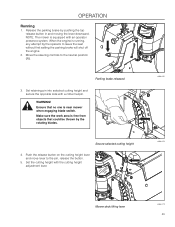
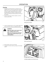
.... 2. Make sure the work area is equipped with the cutting height adjustment lever. 8058-020 8058-024 Mower deck lifting lever 8058-019 29 When the engine is near mower when engaging blade switch. Push the release button on the cutting height lever and move lever to the neutral position (N). operation Running...
.... 2. Make sure the work area is equipped with the cutting height adjustment lever. 8058-020 8058-024 Mower deck lifting lever 8058-019 29 When the engine is near mower when engaging blade switch. Push the release button on the cutting height lever and move lever to the neutral position (N). operation Running...
Owners Manual
Page 30
... right control towards the neutral position. Do not drive across slopes. • The slowest speed possible should be achieved by pulling out the blade switch. 7. This may cause the mower to suddenly stop. • To restart movement, release the parking brake. • Pull the control levers... back to the center of the mower and press forward to neutral when released. Engage the mower deck by moving one control backward (behind the neutral position) and carefully moving both controls are continuously variable using the two steering controls. Do...
... right control towards the neutral position. Do not drive across slopes. • The slowest speed possible should be achieved by pulling out the blade switch. 7. This may cause the mower to suddenly stop. • To restart movement, release the parking brake. • Pull the control levers... back to the center of the mower and press forward to neutral when released. Engage the mower deck by moving one control backward (behind the neutral position) and carefully moving both controls are continuously variable using the two steering controls. Do...
Owners Manual
Page 32
Raise the mower deck • Move the throttle to stop position. • Move the steering controls outward. • Remove key. Always remove key when leaving the mower to prevent unauthorized use. 8058-019 IMPORTANT INFORMATION Leaving the ignition switch in any other position than "OFF" will ... machine is a risk of the spark plugs fouling. • Disengage the mower deck by depressing the blade switch. 8058-134 Disengage the mower deck and move throttle to minimum • Raise the mower deck by pushing the lever release button and pulling the lever upward. Avoid idling the engine...
Raise the mower deck • Move the throttle to stop position. • Move the steering controls outward. • Remove key. Always remove key when leaving the mower to prevent unauthorized use. 8058-019 IMPORTANT INFORMATION Leaving the ignition switch in any other position than "OFF" will ... machine is a risk of the spark plugs fouling. • Disengage the mower deck by depressing the blade switch. 8058-134 Disengage the mower deck and move throttle to minimum • Raise the mower deck by pushing the lever release button and pulling the lever upward. Avoid idling the engine...
Owners Manual
Page 35
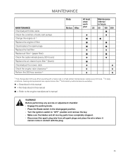
... plug. 35 Before performing any service or adjustment checklist • Engage the parking brake. • Place the Blade-switch in the disengaged position. • Turn the ignition switch to "OFF" position and remove the key. • Make sure the blades and all moving parts have completely stopped...2) (paper filter) Check the caster wheels (every 200 hours) Replace the air cleaner's pre-filter 2) (foam) Check/adjust the mower deck Check the engine valve clearance 3) Perform the 300-hour service 3) Daily Before After At least once each year 25 Maintenance interval in this manual...
... plug. 35 Before performing any service or adjustment checklist • Engage the parking brake. • Place the Blade-switch in the disengaged position. • Turn the ignition switch to "OFF" position and remove the key. • Make sure the blades and all moving parts have completely stopped...2) (paper filter) Check the caster wheels (every 200 hours) Replace the air cleaner's pre-filter 2) (foam) Check/adjust the mower deck Check the engine valve clearance 3) Perform the 300-hour service 3) Daily Before After At least once each year 25 Maintenance interval in this manual...
Owners Manual
Page 47
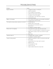
... the transmission slack or has come off • Air trapped in hydraulic system • Drive belt for the mower deck has come loose • Contact for the electromagnetic coupling has loosened • Blade switch is faulty or has come loose from cable contact • Blown fuse • Damaged seals, housing, or gaskets...
... the transmission slack or has come off • Air trapped in hydraulic system • Drive belt for the mower deck has come loose • Contact for the electromagnetic coupling has loosened • Blade switch is faulty or has come loose from cable contact • Blown fuse • Damaged seals, housing, or gaskets...

Owners Manual
Page 58
...wheels to 15 PSI (1 bar) Mount the steering controls in the normal position Connect the contact box to the cable for the seat's safety switch Check that the right amount of oil is in the engine Adjust the position of the steering controls Fill with fuel and open the fuel... Start the engine Check that there is drive to both wheels Check the mower deck adjustment Check: The safety switch for the parking brake The safety switch for the mower deck The safety switch in the seat The safety switch in the steering controls Parking brake functionality Driving forward Driving backward Engaging the blades ...
...wheels to 15 PSI (1 bar) Mount the steering controls in the normal position Connect the contact box to the cable for the seat's safety switch Check that the right amount of oil is in the engine Adjust the position of the steering controls Fill with fuel and open the fuel... Start the engine Check that there is drive to both wheels Check the mower deck adjustment Check: The safety switch for the parking brake The safety switch for the mower deck The safety switch in the seat The safety switch in the steering controls Parking brake functionality Driving forward Driving backward Engaging the blades ...

Owners Manual
Page 3
...16 Spark Arrestor 16 Transport 16 CONTROLS 17 Control Locations 17 Steering Control Levers 18 Parking Brake 19 Throttle Control 19 Blade Switch 19 Ignition Switch 20 Choke Control 20 Fuses 20 Fuel Tank 21 Fuel Shut Off Valve 22 Cutting Height Adjuster 22 Bypass Linkages 22 Seat...Battery 37 Safety System 38 Parking Brake 38 Tire Pressures 39 Anti-scalp Rollers 39 V-belts 40 Deck Belt Removal 40 Cutting Blades 41 Blade replacement 41 Adjusting the Mower Deck 42 Leveling deck 42 Caster Wheels 43 Cleaning 43 Hardware 43 LUBRICATION 44 Lubrication Schedule 44 Wheel and...
...16 Spark Arrestor 16 Transport 16 CONTROLS 17 Control Locations 17 Steering Control Levers 18 Parking Brake 19 Throttle Control 19 Blade Switch 19 Ignition Switch 20 Choke Control 20 Fuses 20 Fuel Tank 21 Fuel Shut Off Valve 22 Cutting Height Adjuster 22 Bypass Linkages 22 Seat...Battery 37 Safety System 38 Parking Brake 38 Tire Pressures 39 Anti-scalp Rollers 39 V-belts 40 Deck Belt Removal 40 Cutting Blades 41 Blade replacement 41 Adjusting the Mower Deck 42 Leveling deck 42 Caster Wheels 43 Cleaning 43 Hardware 43 LUBRICATION 44 Lubrication Schedule 44 Wheel and...
Owners Manual
Page 17
... overhead valve engine. Seat adjustment lever 9. Parking brake 3. Fuses 8. Throttle 12. Tracking adjustment 4. Blade switch 10. CONTROLS This operator's manual describes the Husqvarna Zero Turn Rider. driven hydraulic pumps. Control Locations 4 3 2 5 1 5 6 7 8 9 10 11 12 13 14 1. Ignition switch 11. Hour meter 14. The rider is regulated and thereby the direction and speed. Transmission...
... overhead valve engine. Seat adjustment lever 9. Parking brake 3. Fuses 8. Throttle 12. Tracking adjustment 4. Blade switch 10. CONTROLS This operator's manual describes the Husqvarna Zero Turn Rider. driven hydraulic pumps. Control Locations 4 3 2 5 1 5 6 7 8 9 10 11 12 13 14 1. Ignition switch 11. Hour meter 14. The rider is regulated and thereby the direction and speed. Transmission...

Owners Manual
Page 19
... or back respectively. The mower blades are disengaged when the knob is a risk of fouling the spark plugs. Throttle control Blade Switch To engage the mower deck, pull the blade switch knob out. CONTROLS Parking Brake IMPORTANT INFORMATION The machine must be not be moving the mower. Always set the parking brake before...
... or back respectively. The mower blades are disengaged when the knob is a risk of fouling the spark plugs. Throttle control Blade Switch To engage the mower deck, pull the blade switch knob out. CONTROLS Parking Brake IMPORTANT INFORMATION The machine must be not be moving the mower. Always set the parking brake before...

Owners Manual
Page 20
...with a richer fuel mixture. For cold starts on models with ratings and functions: 20 Amp Primary fuse 7.5 Amp Mower deck coupling Fuses 20 8058-134 8058-134 8011-420 Ignition switch Choke Control The choke control is used in automobiles. They are located on the left hand side of the same...the engine. There are flat pin fuses of the machine. Choke control Fuses Fuses are accessed by tilting the seat forward. CONTROLS Ignition Switch The ignition switch is placed on the control panel and is used for cold starts to ACCESSORY for headlight use. They are two fuses with separate ...
...with a richer fuel mixture. For cold starts on models with ratings and functions: 20 Amp Primary fuse 7.5 Amp Mower deck coupling Fuses 20 8058-134 8058-134 8011-420 Ignition switch Choke Control The choke control is used in automobiles. They are located on the left hand side of the same...the engine. There are flat pin fuses of the machine. Choke control Fuses Fuses are accessed by tilting the seat forward. CONTROLS Ignition Switch The ignition switch is placed on the control panel and is used for cold starts to ACCESSORY for headlight use. They are two fuses with separate ...

Owners Manual
Page 25
Check that there is sufficient fuel in the Maintenance section). 3. Adjust the seat to the desired position. Set the deck cutting height by inserting the lift pin into the activated position. • Both steering controls must be in the locked (outer) neutral position. ... before starting the machine. 2. OPERATION Before Starting 1. Read the sections on Safety and Controls before the engine can be started: • The blade switch must be pressed downward into the disengaged position. • The parking brake must be up into the desired cut height. Resecure the lift pin with...
Check that there is sufficient fuel in the Maintenance section). 3. Adjust the seat to the desired position. Set the deck cutting height by inserting the lift pin into the activated position. • Both steering controls must be in the locked (outer) neutral position. ... before starting the machine. 2. OPERATION Before Starting 1. Read the sections on Safety and Controls before the engine can be started: • The blade switch must be pressed downward into the disengaged position. • The parking brake must be up into the desired cut height. Resecure the lift pin with...

Owners Manual
Page 26
Pull the lifting lever backward to activate. 8058-187 Blade switch 8058-134 26 Mower deck lifting lever 3. Sit on the top of the lifting lever. Raise the mower deck by pushing the release button on the seat. 2. Disengage the mower blades by pushing the release button in and pulling the lever fully upwards. 8058-019 4. Pull parking brake upwards to the locked (transport) position. Activate the parking brake by pressing the blade switch downwards. OPERATION Starting the Engine 1.
Pull the lifting lever backward to activate. 8058-187 Blade switch 8058-134 26 Mower deck lifting lever 3. Sit on the top of the lifting lever. Raise the mower deck by pushing the release button on the seat. 2. Disengage the mower blades by pushing the release button in and pulling the lever fully upwards. 8058-019 4. Pull parking brake upwards to the locked (transport) position. Activate the parking brake by pressing the blade switch downwards. OPERATION Starting the Engine 1.
Owners Manual
Page 30
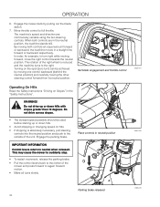
...the neutral position (N). Make sure that could be thrown by pushing the top release button in and moving the lever downward. Engage the mower deck by the operator to leave the seat without first setting the parking brake will shut off the engine. 2. NOTE: The mower is running,... engagement and throttle control 8058-149 30 Make sure the work area is free from objects that no one is near mower when engaging blade switch. When the engine is equipped with an operator presence system. Parking brake released 3. Release the parking brake by the rotating blades. WARNING! ...
...the neutral position (N). Make sure that could be thrown by pushing the top release button in and moving the lever downward. Engage the mower deck by the operator to leave the seat without first setting the parking brake will shut off the engine. 2. NOTE: The mower is running,... engagement and throttle control 8058-149 30 Make sure the work area is free from objects that no one is near mower when engaging blade switch. When the engine is equipped with an operator presence system. Parking brake released 3. Release the parking brake by the rotating blades. WARNING! ...

Owners Manual
Page 33
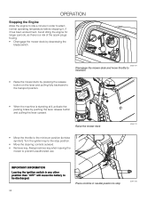
Raise the mower deck by pressing the blade switch down. 8058-134 Disengage the mower deck and move throttle to the transport position. 5. Remove key. To prevent fouling the spark plugs, avoid idling the engine for longer periods. If the engine ... it to idle at least 60 seconds to the minimum position (tortoise symbol). 2. Disengage the mower deck by pressing the release button on the lever and pulling the lever upward to minimum 4. Raise the mower deck 6. Move the throttle to attain a normal operating temperature before stopping. When the machine is standing still...
Raise the mower deck by pressing the blade switch down. 8058-134 Disengage the mower deck and move throttle to the transport position. 5. Remove key. To prevent fouling the spark plugs, avoid idling the engine for longer periods. If the engine ... it to idle at least 60 seconds to the minimum position (tortoise symbol). 2. Disengage the mower deck by pressing the release button on the lever and pulling the lever upward to minimum 4. Raise the mower deck 6. Move the throttle to attain a normal operating temperature before stopping. When the machine is standing still...

Owners Manual
Page 36
Before performing any service or adjustment checklist: • Engage the parking brake. • Place the Blade-switch in the disengaged position. • Turn the ignition switch to the engine manufacturer's manual WARNING! MAINTENANCE MAINTENANCE Check/adjust throttle cable Check the condition of belts, ...(paper filter) Check the caster wheels (every 200 hours) Replace the air cleaner's pre-filter 2) (foam) Check/adjust the mower deck Check the engine valve clearance 3) Perform the 300-hour service 3) Daily At least once each Before After year 25 Maintenance interval in ...
Before performing any service or adjustment checklist: • Engage the parking brake. • Place the Blade-switch in the disengaged position. • Turn the ignition switch to the engine manufacturer's manual WARNING! MAINTENANCE MAINTENANCE Check/adjust throttle cable Check the condition of belts, ...(paper filter) Check the caster wheels (every 200 hours) Replace the air cleaner's pre-filter 2) (foam) Check/adjust the mower deck Check the engine valve clearance 3) Perform the 300-hour service 3) Daily At least once each Before After year 25 Maintenance interval in ...


