Owner's Manual
Page 1
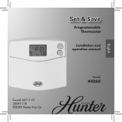
Set & $ave Programmable Thermostat installation and operation manual English Form# 42711-01 20091118 ©2009 Hunter Fan Co. 1 Model 44260
Set & $ave Programmable Thermostat installation and operation manual English Form# 42711-01 20091118 ©2009 Hunter Fan Co. 1 Model 44260
Owner's Manual
Page 3
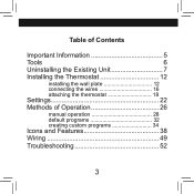
Table of Contents Important Information 5 Tools 6 Uninstalling the Existing Unit 7 Installing the Thermostat 12 installing the wall plate 12 connecting the wires 16 attaching the thermostat 18 Settings 22 Methods of Operation 26 manual operation 28 default programs 32 creating custom programs 34 Icons and Features 38 Wiring 49 Troubleshooting 52 3
Table of Contents Important Information 5 Tools 6 Uninstalling the Existing Unit 7 Installing the Thermostat 12 installing the wall plate 12 connecting the wires 16 attaching the thermostat 18 Settings 22 Methods of Operation 26 manual operation 28 default programs 32 creating custom programs 34 Icons and Features 38 Wiring 49 Troubleshooting 52 3
Owner's Manual
Page 4
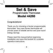
Please read this manual before beginning installation and save this booklet for choosing a Hunter programmable thermostat. Set & Save Programmable Thermostat Model 44260 Congratulations! Thank you for complete operation instructions. 4 Your new Hunter thermostat will provide years of reliable service and year-round energy savings.
Please read this manual before beginning installation and save this booklet for choosing a Hunter programmable thermostat. Set & Save Programmable Thermostat Model 44260 Congratulations! Thank you for complete operation instructions. 4 Your new Hunter thermostat will provide years of reliable service and year-round energy savings.

Owner's Manual
Page 6
To install your new thermostat, you will need the following supplies: Flat-head screwdriver Small Phillips-head screwdriver Hammer Electric drill and 3/16" bit Two 1.5 Volt (AA) size alkaline batteries 6 Tools This thermostat includes two #8 slotted screws and two wall anchors for mounting.
To install your new thermostat, you will need the following supplies: Flat-head screwdriver Small Phillips-head screwdriver Hammer Electric drill and 3/16" bit Two 1.5 Volt (AA) size alkaline batteries 6 Tools This thermostat includes two #8 slotted screws and two wall anchors for mounting.
Owner's Manual
Page 13
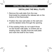
Position the new wall plate on the Hunter wall plate, or if there are no existing holes, visually level the wall plate and mark the wall for two holes. 13 installing the thermostat INSTALLING THE WALL PLATE 1. If the existing holes do not match those on the wall and pull the labeled wires through the opening. 3. Remove the wall plate from the new thermostat by pressing the release tab on the bottom of the thermostat. 2.
Position the new wall plate on the Hunter wall plate, or if there are no existing holes, visually level the wall plate and mark the wall for two holes. 13 installing the thermostat INSTALLING THE WALL PLATE 1. If the existing holes do not match those on the wall and pull the labeled wires through the opening. 3. Remove the wall plate from the new thermostat by pressing the release tab on the bottom of the thermostat. 2.
Owner's Manual
Page 15
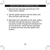
Reposition the wall plate on the wall, pulling the wires through the wall plate and into the holes until they are flush with the wall. 6. Verify that the wall plate is visually level and securely tighten both screws. 15 Tap the plastic anchors into the anchors. Insert the mounting screws through the opening. Remove the wall plate and drill two 3/16" holes where marked. 5. installing the thermostat, cont. 4.
Reposition the wall plate on the wall, pulling the wires through the wall plate and into the holes until they are flush with the wall. 6. Verify that the wall plate is visually level and securely tighten both screws. 15 Tap the plastic anchors into the anchors. Insert the mounting screws through the opening. Remove the wall plate and drill two 3/16" holes where marked. 5. installing the thermostat, cont. 4.

Owner's Manual
Page 17
.... Tighten each screw after the connection has been made. (The ends of any excess wire length back into the wall.) 3. Jumper G RC RH Y W place. installing the thermostat, cont. Note: A jumper wire has been provided, connecting the RC and RH terminals for systems that do not remove, the terminal screws. CONNECTING THE WIRES...
.... Tighten each screw after the connection has been made. (The ends of any excess wire length back into the wall.) 3. Jumper G RC RH Y W place. installing the thermostat, cont. Note: A jumper wire has been provided, connecting the RC and RH terminals for systems that do not remove, the terminal screws. CONNECTING THE WIRES...
Owner's Manual
Page 19
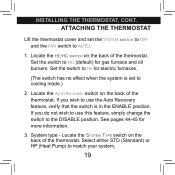
... you do not wish to HE for more information. 3. Locate the HE/HG switch on the back of the thermostat. Select either STD (Standard) or HP (Heat Pump) to HG (default) for gas furnace and oil burners. Set the switch to use the Auto Recovery ... is set the SYSTEM switch to OFF and the FAN switch to the DISABLE position. System type - Set the switch to match your system. 19 installing the thermostat, cont. ATTACHING THE THERMOSTAT Lift the thermostat cover and set to cooling mode.) 2. Locate the Auto Recovery switch on the back of the...
... you do not wish to HE for more information. 3. Locate the HE/HG switch on the back of the thermostat. Select either STD (Standard) or HP (Heat Pump) to HG (default) for gas furnace and oil burners. Set the switch to use the Auto Recovery ... is set the SYSTEM switch to OFF and the FAN switch to the DISABLE position. System type - Set the switch to match your system. 19 installing the thermostat, cont. ATTACHING THE THERMOSTAT Lift the thermostat cover and set to cooling mode.) 2. Locate the Auto Recovery switch on the back of the...

Owner's Manual
Page 21
Press the thermostat onto the wall plate and press to snap the bottom tab into place properly, the unit may be damaged. If the thermostat does not snap into place. Insert two AA alkaline batteries. 6. Note: Do not force the thermostat onto the wall plate, as the terminal pins may not work. 5. Restore power at the electrical panel or furnace. 21 Place the top of the thermostat over the two tabs on the wall plate. installing the thermostat, cont. 4.
Press the thermostat onto the wall plate and press to snap the bottom tab into place properly, the unit may be damaged. If the thermostat does not snap into place. Insert two AA alkaline batteries. 6. Note: Do not force the thermostat onto the wall plate, as the terminal pins may not work. 5. Restore power at the electrical panel or furnace. 21 Place the top of the thermostat over the two tabs on the wall plate. installing the thermostat, cont. 4.
Owner's Manual
Page 43
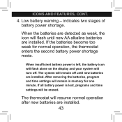
...remain in memory for normal operation, the thermostat enters the second battery power shortage mode. When the batteries are detected as weak, the icon will remain off . The system will flash until new batteries are installed. The thermostat will turn off until new AA alkaline ...batteries are installed. ICONS AND FEATURES, cont. 4. indicates two stages of battery power shortage. If the batteries become too...
...remain in memory for normal operation, the thermostat enters the second battery power shortage mode. When the batteries are detected as weak, the icon will remain off . The system will flash until new batteries are installed. The thermostat will turn off until new AA alkaline ...batteries are installed. ICONS AND FEATURES, cont. 4. indicates two stages of battery power shortage. If the batteries become too...


