Owner's Manual
Page 3
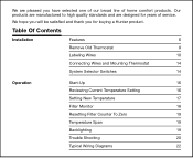
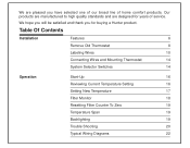
Table Of Contents Installation Features 6 Remove Old Thermostat 8 Labeling Wires 10 Connecting Wires and Mounting Thermostat 14 System Selector Switches 14 Operation Start-Up 16 Reviewing Current Temperature Setting 16 Setting New Temperature 17 Filter Monitor 18 Resetting Filter Counter To ... of service. Our products are manufactured to high quality standards and are pleased you for years of home comfort products. We are designed for buying a Hunter product.
Table Of Contents Installation Features 6 Remove Old Thermostat 8 Labeling Wires 10 Connecting Wires and Mounting Thermostat 14 System Selector Switches 14 Operation Start-Up 16 Reviewing Current Temperature Setting 16 Setting New Temperature 17 Filter Monitor 18 Resetting Filter Counter To ... of service. Our products are manufactured to high quality standards and are pleased you for years of home comfort products. We are designed for buying a Hunter product.
Owner's Manual
Page 4
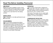
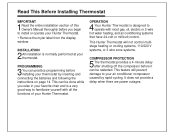
... chair and is normally performed at your thermostat. This Hunter Thermostat will prevent damage to familiarize yourself with most gas, oil, electric or 2-wire hot water heating, and air conditioning systems that have 24-volt or millivolt control. PROGRAMMING 3You can be restarted. Read This Before Installing Thermostat IMPORTANT 1Read the entire installation section of your Hunter Thermostat.
... chair and is normally performed at your thermostat. This Hunter Thermostat will prevent damage to familiarize yourself with most gas, oil, electric or 2-wire hot water heating, and air conditioning systems that have 24-volt or millivolt control. PROGRAMMING 3You can be restarted. Read This Before Installing Thermostat IMPORTANT 1Read the entire installation section of your Hunter Thermostat.

Owner's Manual
Page 5
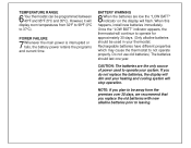
...battery power retains the programs and current time. BATTERY WARNING 8When the batteries are the only source of power used in your thermostat. NOTE: If you replace the old batteries with new alkaline batteries prior to operate for approximately 30 days. (Only alkaline ...batteries should last one year. When this happens, install new batteries immediately. Rechargeable batteries have different properties which may cause the thermostat to 37°C). However, it will continue to leaving. Once the "LOW BATT" indicator appears...
...battery power retains the programs and current time. BATTERY WARNING 8When the batteries are the only source of power used in your thermostat. NOTE: If you replace the old batteries with new alkaline batteries prior to operate for approximately 30 days. (Only alkaline ...batteries should last one year. When this happens, install new batteries immediately. Rechargeable batteries have different properties which may cause the thermostat to 37°C). However, it will continue to leaving. Once the "LOW BATT" indicator appears...
Owner's Manual
Page 8
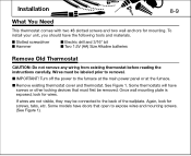
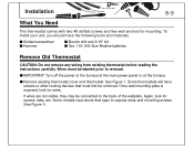
... to removal. s If wires are not visible, they may be removed. Again, look for mounting. s Remove existing thermostat cover and thermostat. Turn off the power to the back of the wallplate. Installation 8-9 What You Need This thermostat comes with two #8 slotted screws and two wall anchors for wires. Wires must first be connected to...
... to removal. s If wires are not visible, they may be removed. Again, look for mounting. s Remove existing thermostat cover and thermostat. Turn off the power to the back of the wallplate. Installation 8-9 What You Need This thermostat comes with two #8 slotted screws and two wall anchors for wires. Wires must first be connected to...
Owner's Manual
Page 10
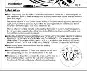
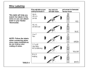
... TABLE A ON PAGE 11. (For example, attach the label marked W to the wire which goes to the W or H terminal on the existing thermostat of two wire, heat only systems. Do not worry, just connect either of wires in wall is larger than necessary for heat only systems), as...not always comply with a code letter as two (for wires, seal this hole so that thermostat. Each of the thermostat from the wall. Installation 10-11 Label Wires s Each wire coming from the wall to the existing thermostat is connected to a terminal point on page 9. s After labeling wires, disconnect them to ...
... TABLE A ON PAGE 11. (For example, attach the label marked W to the wire which goes to the W or H terminal on the existing thermostat of two wire, heat only systems. Do not worry, just connect either of wires in wall is larger than necessary for heat only systems), as...not always comply with a code letter as two (for wires, seal this hole so that thermostat. Each of the thermostat from the wall. Installation 10-11 Label Wires s Each wire coming from the wall to the existing thermostat is connected to a terminal point on page 9. s After labeling wires, disconnect them to ...
Owner's Manual
Page 11
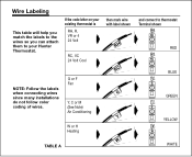
If the code letter on your Hunter Thermostat. G or F Fan Y, C or M (See Note) Air Conditioning then mark wire with label shown RH RC G Y W or H Heating W TABLE A and connect to your existing thermostat is RH, R, VR or 4 24 Volt RC, VC 24 Volt Cool NOTE: Follow the labels when connecting wires since many installations do not follow color coding of wires. Wire Labeling This table will help you match the labels to the wires so you can attach them to thermostat Terminal shown RH RH RED RC RC BLUE G G GREEN Y Y YELLOW W W WHITE
If the code letter on your Hunter Thermostat. G or F Fan Y, C or M (See Note) Air Conditioning then mark wire with label shown RH RC G Y W or H Heating W TABLE A and connect to your existing thermostat is RH, R, VR or 4 24 Volt RC, VC 24 Volt Cool NOTE: Follow the labels when connecting wires since many installations do not follow color coding of wires. Wire Labeling This table will help you match the labels to the wires so you can attach them to thermostat Terminal shown RH RH RED RC RC BLUE G G GREEN Y Y YELLOW W W WHITE
Owner's Manual
Page 12
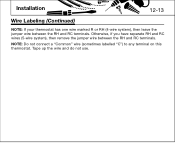
NOTE: Do not connect a "Common" wire (sometimes labelled "C") to any terminal on this thermostat. Tape up the wire and do not use. Otherwise, if you have separate RH and RC wires (5-wire system), then remove the jumper wire between the RH and RC terminals. Installation 12-13 Wire Labeling (Continued) NOTE: If your thermostat has one wire marked R or RH (4-wire system), then leave the jumper wire between the RH and RC terminals.
NOTE: Do not connect a "Common" wire (sometimes labelled "C") to any terminal on this thermostat. Tape up the wire and do not use. Otherwise, if you have separate RH and RC wires (5-wire system), then remove the jumper wire between the RH and RC terminals. Installation 12-13 Wire Labeling (Continued) NOTE: If your thermostat has one wire marked R or RH (4-wire system), then leave the jumper wire between the RH and RC terminals.
Owner's Manual
Page 14
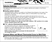
... but which were not connected to see whether the heat and fan come on when the thermostat calls for F° mode from the factory. The switch is located near the display. Installation 14-15 Selector Switches The heating system selector and the F°/C° selector switches are located... on the inside of the thermostat with a paper clip. If you have an electric furnace, test to the old thermostat. If the fan does not come...
... but which were not connected to see whether the heat and fan come on when the thermostat calls for F° mode from the factory. The switch is located near the display. Installation 14-15 Selector Switches The heating system selector and the F°/C° selector switches are located... on the inside of the thermostat with a paper clip. If you have an electric furnace, test to the old thermostat. If the fan does not come...
Owner's Manual
Page 15
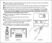
s Make sure the Function Switch is set at the bottom of the thermostat cover. If it does not snap properly, the thermostat may be damaged. s The installation is in AUTO. Continue reading Owner's Manual for complete operating instructions. s Push excess wire back into the slot at OFF, and the FAN-AUTO Switch ...
s Make sure the Function Switch is set at the bottom of the thermostat cover. If it does not snap properly, the thermostat may be damaged. s The installation is in AUTO. Continue reading Owner's Manual for complete operating instructions. s Push excess wire back into the slot at OFF, and the FAN-AUTO Switch ...

Owner's Manual
Page 16
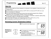
... than 2 68 TEMP SET TEMP F FILTER seconds, you first install two AA size batteries, as directed in timer prevents damage to 35°C). Replace batteries as soon as explained below. s The thermostat will prevent memory loss and avoid reprogramming. LO BAT ting as low... battery indicator comes on the display. s If pressed for cool. s A built-in the installation instructions, press the Reset Button.
... than 2 68 TEMP SET TEMP F FILTER seconds, you first install two AA size batteries, as directed in timer prevents damage to 35°C). Replace batteries as soon as explained below. s The thermostat will prevent memory loss and avoid reprogramming. LO BAT ting as low... battery indicator comes on the display. s If pressed for cool. s A built-in the installation instructions, press the Reset Button.
Owner's Manual
Page 3
... satisfied and thank you have selected one of our broad line of service. We are designed for buying a Hunter product. Table Of Contents Installation Features 6 Remove Old Thermostat 8 Labeling Wires 10 Connecting Wires and Mounting Thermostat 14 System Selector Switches 14 Operation Start-Up 16 Reviewing Current Temperature Setting 16 Setting New Temperature 17...
... satisfied and thank you have selected one of our broad line of service. We are designed for buying a Hunter product. Table Of Contents Installation Features 6 Remove Old Thermostat 8 Labeling Wires 10 Connecting Wires and Mounting Thermostat 14 System Selector Switches 14 Operation Start-Up 16 Reviewing Current Temperature Setting 16 Setting New Temperature 17...
Owner's Manual
Page 4
... by inserting and connecting the batteries and following the instructions on page 14. OPERATION 4 Your Hunter Thermostat is designed to install or operate your Hunter Thermostat. • Remove the mylar label from the display window. It does not provide a delay...operate with all the functions of this Owner's Manual thoroughly before installing your thermostat by rapid cycling. Read This Before Installing Thermostat IMPORTANT 1Read the entire installation section of your Hunter Thermostat. This Hunter Thermostat will prevent damage to familiarize yourself with most gas, oil, ...
... by inserting and connecting the batteries and following the instructions on page 14. OPERATION 4 Your Hunter Thermostat is designed to install or operate your Hunter Thermostat. • Remove the mylar label from the display window. It does not provide a delay...operate with all the functions of this Owner's Manual thoroughly before installing your thermostat by rapid cycling. Read This Before Installing Thermostat IMPORTANT 1Read the entire installation section of your Hunter Thermostat. This Hunter Thermostat will prevent damage to familiarize yourself with most gas, oil, ...
Owner's Manual
Page 5
...be used to not operate properly. CAUTION: The batteries are low the "LOW BATT" indicator on the display will stop operation. When this happens, install new batteries immediately. If you do not replace the batteries, the display will dim and your heating and cooling system will flash. BATTERY WARNING 8When... prior to leaving. However, it will continue to operate for approximately 30 days. (Only alkaline batteries should last one year. TEMPERATURE RANGE 6Your thermostat can be away from 32°F to 99°F (0°C to 37°C). Once the "LOW BATT" indicator appears, the...
...be used to not operate properly. CAUTION: The batteries are low the "LOW BATT" indicator on the display will stop operation. When this happens, install new batteries immediately. If you do not replace the batteries, the display will dim and your heating and cooling system will flash. BATTERY WARNING 8When... prior to leaving. However, it will continue to operate for approximately 30 days. (Only alkaline batteries should last one year. TEMPERATURE RANGE 6Your thermostat can be away from 32°F to 99°F (0°C to 37°C). Once the "LOW BATT" indicator appears, the...
Owner's Manual
Page 8
..." bit s Two 1.5V (AA) Size Alkaline batteries Remove Old Thermostat CAUTION: Do not remove any wiring from existing thermostat before reading the instructions carefully. Once wall mounting plate is exposed, look for mounting. s Remove existing thermostat cover and thermostat. s IMPORTANT! Installation 8-9 What You Need This thermostat comes with two #8 slotted screws and two wall anchors for...
..." bit s Two 1.5V (AA) Size Alkaline batteries Remove Old Thermostat CAUTION: Do not remove any wiring from existing thermostat before reading the instructions carefully. Once wall mounting plate is exposed, look for mounting. s Remove existing thermostat cover and thermostat. s IMPORTANT! Installation 8-9 What You Need This thermostat comes with two #8 slotted screws and two wall anchors for...
Owner's Manual
Page 10
... labeling wires, disconnect them to the wall. If you follow the labeling procedures correctly, you may want to tape them from the existing thermostat terminals. s Remove existing wallplate. To make sure wires do not fall back into wall opening, you do not always comply with a ... A on page 9. This air could cause a false thermostat reading. s IMPORTANT! Installation 10-11 Label Wires s Each wire coming from the wall to the existing thermostat is connected to a terminal point on that no terminal marking on the existing thermostat of two wire, heat only systems. Do not worry...
... labeling wires, disconnect them to the wall. If you follow the labeling procedures correctly, you may want to tape them from the existing thermostat terminals. s Remove existing wallplate. To make sure wires do not fall back into wall opening, you do not always comply with a ... A on page 9. This air could cause a false thermostat reading. s IMPORTANT! Installation 10-11 Label Wires s Each wire coming from the wall to the existing thermostat is connected to a terminal point on that no terminal marking on the existing thermostat of two wire, heat only systems. Do not worry...
Owner's Manual
Page 11
Wire Labeling This table will help you match the labels to the wires so you can attach them to thermostat Terminal shown RH RH RED RC RC BLUE G G GREEN Y Y YELLOW W W WHITE G or F Fan Y, C or M (See Note) Air Conditioning then mark wire with label shown RH RC G Y W or H Heating W TABLE A and connect to your existing thermostat is RH, R, VR or 4 24 Volt RC, VC 24 Volt Cool NOTE: Follow the labels when connecting wires since many installations do not follow color coding of wires. If the code letter on your Hunter Thermostat.
Wire Labeling This table will help you match the labels to the wires so you can attach them to thermostat Terminal shown RH RH RED RC RC BLUE G G GREEN Y Y YELLOW W W WHITE G or F Fan Y, C or M (See Note) Air Conditioning then mark wire with label shown RH RC G Y W or H Heating W TABLE A and connect to your existing thermostat is RH, R, VR or 4 24 Volt RC, VC 24 Volt Cool NOTE: Follow the labels when connecting wires since many installations do not follow color coding of wires. If the code letter on your Hunter Thermostat.

Owner's Manual
Page 12
NOTE: Do not connect a "Common" wire (sometimes labelled "C") to any terminal on this thermostat. Tape up the wire and do not use. Installation 12-13 Wire Labeling (Continued) NOTE: If your thermostat has one wire marked R or RH (4-wire system), then leave the jumper wire between the RH and RC terminals. Otherwise, if you have separate RH and RC wires (5-wire system), then remove the jumper wire between the RH and RC terminals.
NOTE: Do not connect a "Common" wire (sometimes labelled "C") to any terminal on this thermostat. Tape up the wire and do not use. Installation 12-13 Wire Labeling (Continued) NOTE: If your thermostat has one wire marked R or RH (4-wire system), then leave the jumper wire between the RH and RC terminals. Otherwise, if you have separate RH and RC wires (5-wire system), then remove the jumper wire between the RH and RC terminals.
Owner's Manual
Page 14
...C° and press reset button on the inside of the thermostat with a paper clip. The system selector has no effect in the "HG" position. In order to change the switch position to the old thermostat. Installation 14-15 Selector Switches The heating system selector and the F°...;/C° selector switches are located on when the thermostat calls for F° mode from the factory. s Heating system selector The ...
...C° and press reset button on the inside of the thermostat with a paper clip. The system selector has no effect in the "HG" position. In order to change the switch position to the old thermostat. Installation 14-15 Selector Switches The heating system selector and the F°...;/C° selector switches are located on when the thermostat calls for F° mode from the factory. s Heating system selector The ...
Owner's Manual
Page 15
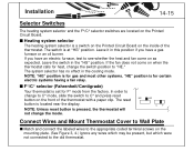
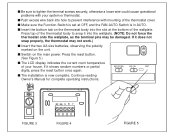
... slot at OFF, and the FAN-AUTO Switch is in AUTO. s Switch on the unit. s The installation is set at the bottom of the wallplate. Press top of the thermostat body to snap it into hole to tighten the terminal screws securely, otherwise a loose wire could cause operational... is now complete. Press the reset button. (See Figure 5.) s The LCD display indicates the current room temperature of your system or thermostat. If it does not snap properly, the thermostat may be damaged. RH RH RC RH G W Y FIGURE 3 FIGURE 4 FIGURE 5 s Be sure to prevent interference with your house...
... slot at OFF, and the FAN-AUTO Switch is in AUTO. s Switch on the unit. s The installation is set at the bottom of the wallplate. Press top of the thermostat body to snap it into hole to tighten the terminal screws securely, otherwise a loose wire could cause operational... is now complete. Press the reset button. (See Figure 5.) s The LCD display indicates the current room temperature of your system or thermostat. If it does not snap properly, the thermostat may be damaged. RH RH RC RH G W Y FIGURE 3 FIGURE 4 FIGURE 5 s Be sure to prevent interference with your house...
Owner's Manual
Page 16
... it will restart. s Your thermostat batteries will display room temperature from 40°F to 95°F. (5°C to 68°F (20°C) for heat and 78°F (25°C) for more than 2 68 TEMP SET TEMP F FILTER seconds, you first install two AA size batteries, as ...explained below. HOLD HEAT COOL LO BAT ting as directed in timer prevents damage to your air conditioner compressor, caused by rapid cycling, by providing a delay of the thermostat. s Room temperature is current room temperature....
... it will restart. s Your thermostat batteries will display room temperature from 40°F to 95°F. (5°C to 68°F (20°C) for heat and 78°F (25°C) for more than 2 68 TEMP SET TEMP F FILTER seconds, you first install two AA size batteries, as ...explained below. HOLD HEAT COOL LO BAT ting as directed in timer prevents damage to your air conditioner compressor, caused by rapid cycling, by providing a delay of the thermostat. s Room temperature is current room temperature....


