Owner's Manual
Page 3
... broad line of service. We are designed for buying a Hunter product. Our products are manufactured to high quality standards and are pleased you for years of home comfort products. Table Of Contents Installation Features 6 Remove Old Thermostat 8 Labeling Wires 10 Connecting Wires and Mounting Thermostat 14 System Selector Switches 14 Operation Start-Up 16 Reviewing...
... broad line of service. We are designed for buying a Hunter product. Our products are manufactured to high quality standards and are pleased you for years of home comfort products. Table Of Contents Installation Features 6 Remove Old Thermostat 8 Labeling Wires 10 Connecting Wires and Mounting Thermostat 14 System Selector Switches 14 Operation Start-Up 16 Reviewing...
Owner's Manual
Page 4
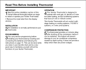
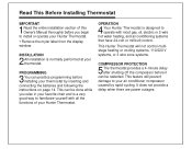
... power outages. This can be restarted. This Hunter Thermostat will prevent damage to operate with all the functions of this Owner's Manual thoroughly before installing your thermostat. This feature will not control multistage heating or cooling systems, 110/220 V systems, or 3 wire zone systems. COMPRESSOR PROTECTION 5The thermostat provides a 4-minute delay after shutting off the...
... power outages. This can be restarted. This Hunter Thermostat will prevent damage to operate with all the functions of this Owner's Manual thoroughly before installing your thermostat. This feature will not control multistage heating or cooling systems, 110/220 V systems, or 3 wire zone systems. COMPRESSOR PROTECTION 5The thermostat provides a 4-minute delay after shutting off the...
Owner's Manual
Page 8
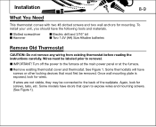
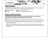
...5V (AA) Size Alkaline batteries Remove Old Thermostat CAUTION: Do not remove any wiring from existing thermostat before reading the instructions carefully. Turn off the power to the back of the wallplate. s Remove existing thermostat cover and thermostat. Some thermostats will have screws or other locking devices that... open to removal. Installation 8-9 What You Need This thermostat comes with two #8 slotted screws and two wall anchors for screws, tabs, etc. Again, look for wires. Once wall mounting plate is exposed, look for mounting. To install ...
...5V (AA) Size Alkaline batteries Remove Old Thermostat CAUTION: Do not remove any wiring from existing thermostat before reading the instructions carefully. Turn off the power to the back of the wallplate. s Remove existing thermostat cover and thermostat. Some thermostats will have screws or other locking devices that... open to removal. Installation 8-9 What You Need This thermostat comes with two #8 slotted screws and two wall anchors for screws, tabs, etc. Again, look for wires. Once wall mounting plate is exposed, look for mounting. To install ...
Owner's Manual
Page 10
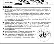
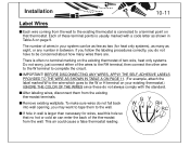
... RH RC Installation 10-11 Label Wires s Each wire coming from the wall to the existing thermostat is connected to a terminal point on that no terminal marking on your system can enter the back of the thermostat from the existing thermostat terminals. s Remove existing wallplate. s... page 9. s After labeling wires, disconnect them to be as few as two (for wires, seal this hole so that thermostat. This air could cause a false thermostat reading. s The number of wires in your existing thermostat.) IGNORE THE COLOR OF THE WIRES since these terminal points is usually...
... RH RC Installation 10-11 Label Wires s Each wire coming from the wall to the existing thermostat is connected to a terminal point on that no terminal marking on your system can enter the back of the thermostat from the existing thermostat terminals. s Remove existing wallplate. s... page 9. s After labeling wires, disconnect them to be as few as two (for wires, seal this hole so that thermostat. This air could cause a false thermostat reading. s The number of wires in your existing thermostat.) IGNORE THE COLOR OF THE WIRES since these terminal points is usually...
Owner's Manual
Page 11
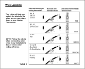
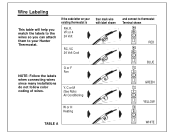
If the code letter on your Hunter Thermostat. Wire Labeling This table will help you match the labels to the wires so you can attach them to thermostat Terminal shown RH RH RED RC RC BLUE G G GREEN Y Y YELLOW W W WHITE G or F Fan Y, C or M (See Note) Air Conditioning then mark wire with label shown RH RC G Y W or H Heating W TABLE A and connect to your existing thermostat is RH, R, VR or 4 24 Volt RC, VC 24 Volt Cool NOTE: Follow the labels when connecting wires since many installations do not follow color coding of wires.
If the code letter on your Hunter Thermostat. Wire Labeling This table will help you match the labels to the wires so you can attach them to thermostat Terminal shown RH RH RED RC RC BLUE G G GREEN Y Y YELLOW W W WHITE G or F Fan Y, C or M (See Note) Air Conditioning then mark wire with label shown RH RC G Y W or H Heating W TABLE A and connect to your existing thermostat is RH, R, VR or 4 24 Volt RC, VC 24 Volt Cool NOTE: Follow the labels when connecting wires since many installations do not follow color coding of wires.
Owner's Manual
Page 12
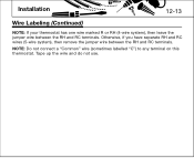
Installation 12-13 Wire Labeling (Continued) NOTE: If your thermostat has one wire marked R or RH (4-wire system), then leave the jumper wire between the RH and RC terminals. Otherwise, if you have separate RH and RC wires (5-wire system), then remove the jumper wire between the RH and RC terminals. Tape up the wire and do not use. NOTE: Do not connect a "Common" wire (sometimes labelled "C") to any terminal on this thermostat.
Installation 12-13 Wire Labeling (Continued) NOTE: If your thermostat has one wire marked R or RH (4-wire system), then leave the jumper wire between the RH and RC terminals. Otherwise, if you have separate RH and RC wires (5-wire system), then remove the jumper wire between the RH and RC terminals. Tape up the wire and do not use. NOTE: Do not connect a "Common" wire (sometimes labelled "C") to any terminal on this thermostat.
Owner's Manual
Page 13
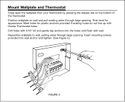
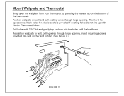
... until flush with Hunter Thermostat holes. Then level for plastic anchors provided if existing holes do not line up with wall. Reposition wallplate to wall, pulling wires through large opening . Mount Wallplate and Thermostat Snap open the wallplate from your thermostat by pressing the ...release tab on wall and pull existing wires through large opening . Mark holes for appearance. Position ...
... until flush with Hunter Thermostat holes. Then level for plastic anchors provided if existing holes do not line up with wall. Reposition wallplate to wall, pulling wires through large opening . Mount Wallplate and Thermostat Snap open the wallplate from your thermostat by pressing the ...release tab on wall and pull existing wires through large opening . Mark holes for appearance. Position ...
Owner's Manual
Page 14
...change to C° mode, slide the switch to the old thermostat. Connect Wires and Mount Thermostat Cover to Wall Plate s Match and connect the labeled wires to the appropriate coded terminal screws on the mounting plate. (See Figure 3, 4.) Ignore any wires which may be present, but which were not connected to C&#...176; and press reset button on when the thermostat calls for heat, change the mode. Leave it in this position if you have a...
...change to C° mode, slide the switch to the old thermostat. Connect Wires and Mount Thermostat Cover to Wall Plate s Match and connect the labeled wires to the appropriate coded terminal screws on the mounting plate. (See Figure 3, 4.) Ignore any wires which may be present, but which were not connected to C&#...176; and press reset button on when the thermostat calls for heat, change the mode. Leave it in this position if you have a...
Owner's Manual
Page 15
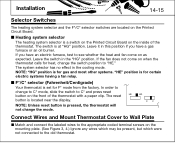
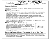
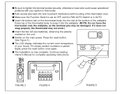
... into hole to tighten the terminal screws securely, otherwise a loose wire could cause operational problems with mounting of the thermostat cover. If it does not snap properly, the thermostat may be damaged. s Push excess wire back into the wallplate. (NOTE: Do not force the thermostat onto the wallplate, as the terminal pins may not work...
... into hole to tighten the terminal screws securely, otherwise a loose wire could cause operational problems with mounting of the thermostat cover. If it does not snap properly, the thermostat may be damaged. s Push excess wire back into the wallplate. (NOTE: Do not force the thermostat onto the wallplate, as the terminal pins may not work...
Owner's Manual
Page 22
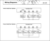
Wiring Diagrams 22-23 4-wire Heat/Cool System THERMOSTAT Jumper RC RH G W Y Heat/Cool Transformer Fan Heat Relay Cool Relay or Valve Contactor 5-wire Heat/Cool System THERMOSTAT RC RH G W Y Cool Heat Fan Heat Relay Cool Transformer Transformer Relay or Valve Contactor
Wiring Diagrams 22-23 4-wire Heat/Cool System THERMOSTAT Jumper RC RH G W Y Heat/Cool Transformer Fan Heat Relay Cool Relay or Valve Contactor 5-wire Heat/Cool System THERMOSTAT RC RH G W Y Cool Heat Fan Heat Relay Cool Transformer Transformer Relay or Valve Contactor
Owner's Manual
Page 23
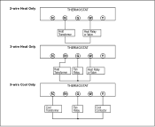
2-wire Heat Only THERMOSTAT RC RH G W Y 3-wire Heat Only Heat Transformer Heat Relay or Valve THERMOSTAT RC RH G W Y 3-wire Cool Only Heat Fan Transformer Relay Heat Relay or Valve THERMOSTAT RC RH G W Y Cool Fan Transformer Relay Cool Contactor
2-wire Heat Only THERMOSTAT RC RH G W Y 3-wire Heat Only Heat Transformer Heat Relay or Valve THERMOSTAT RC RH G W Y 3-wire Cool Only Heat Fan Transformer Relay Heat Relay or Valve THERMOSTAT RC RH G W Y Cool Fan Transformer Relay Cool Contactor
Owner's Manual
Page 3
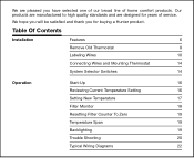
...you have selected one of our broad line of service. Table Of Contents Installation Features 6 Remove Old Thermostat 8 Labeling Wires 10 Connecting Wires and Mounting Thermostat 14 System Selector Switches 14 Operation Start-Up 16 Reviewing Current Temperature Setting 16 Setting New Temperature 17... Counter To Zero 19 Temperature Span 19 Backlighting 19 Trouble Shooting 20 Typical Wiring Diagrams 22 Our products are manufactured to high quality standards and are pleased you for years of home comfort products. We are designed for buying a Hunter product.
...you have selected one of our broad line of service. Table Of Contents Installation Features 6 Remove Old Thermostat 8 Labeling Wires 10 Connecting Wires and Mounting Thermostat 14 System Selector Switches 14 Operation Start-Up 16 Reviewing Current Temperature Setting 16 Setting New Temperature 17... Counter To Zero 19 Temperature Span 19 Backlighting 19 Trouble Shooting 20 Typical Wiring Diagrams 22 Our products are manufactured to high quality standards and are pleased you for years of home comfort products. We are designed for buying a Hunter product.
Owner's Manual
Page 4
OPERATION 4 Your Hunter Thermostat is designed to familiarize yourself with most gas, oil, electric or 2-wire hot water heating, and air conditioning systems that have 24-volt or millivolt control. It does not provide a delay when there are ...power outages. INSTALLATION 2All installation is a very good way to operate with all the functions of this Owner's Manual thoroughly before installing your thermostat by rapid cycling. This Hunter Thermostat...
OPERATION 4 Your Hunter Thermostat is designed to familiarize yourself with most gas, oil, electric or 2-wire hot water heating, and air conditioning systems that have 24-volt or millivolt control. It does not provide a delay when there are ...power outages. INSTALLATION 2All installation is a very good way to operate with all the functions of this Owner's Manual thoroughly before installing your thermostat by rapid cycling. This Hunter Thermostat...
Owner's Manual
Page 8
...look for screws, tabs, etc. s Remove existing thermostat cover and thermostat. Installation 8-9 What You Need This thermostat comes with two #8 slotted screws and two wall anchors for wires. Some thermostats will have the following tools and materials. s If wires are not visible, they may be labeled prior to ...expose wires and mounting screws. (See Figure 1). See Figure 1. To install your unit,...
...look for screws, tabs, etc. s Remove existing thermostat cover and thermostat. Installation 8-9 What You Need This thermostat comes with two #8 slotted screws and two wall anchors for wires. Some thermostats will have the following tools and materials. s If wires are not visible, they may be labeled prior to ...expose wires and mounting screws. (See Figure 1). See Figure 1. To install your unit,...
Owner's Manual
Page 10
... is usually marked with the standard. s After labeling wires, disconnect them to a terminal point on page 9. Each of the thermostat from the existing thermostat terminals. BEFORE DISCONNECTING ANY WIRES, APPLY THE SELF-ADHESIVE LABELS PROVIDED TO THE WIRE AS SHOWN IN TABLE A ON PAGE 11. (For...not have to be as few as two (for wires, seal this hole so that thermostat. GY W RH RC This air could cause a false thermostat reading. Installation 10-11 Label Wires s Each wire coming from the wall to the existing thermostat is connected to the wall. s Remove existing wallplate...
... is usually marked with the standard. s After labeling wires, disconnect them to a terminal point on page 9. Each of the thermostat from the existing thermostat terminals. BEFORE DISCONNECTING ANY WIRES, APPLY THE SELF-ADHESIVE LABELS PROVIDED TO THE WIRE AS SHOWN IN TABLE A ON PAGE 11. (For...not have to be as few as two (for wires, seal this hole so that thermostat. GY W RH RC This air could cause a false thermostat reading. Installation 10-11 Label Wires s Each wire coming from the wall to the existing thermostat is connected to the wall. s Remove existing wallplate...
Owner's Manual
Page 11
Wire Labeling This table will help you match the labels to the wires so you can attach them to thermostat Terminal shown RH RH RED RC RC BLUE G G GREEN Y Y YELLOW W W WHITE If the code letter on your Hunter Thermostat. G or F Fan Y, C or M (See Note) Air Conditioning then mark wire with label shown RH RC G Y W or H Heating W TABLE A and connect to your existing thermostat is RH, R, VR or 4 24 Volt RC, VC 24 Volt Cool NOTE: Follow the labels when connecting wires since many installations do not follow color coding of wires.
Wire Labeling This table will help you match the labels to the wires so you can attach them to thermostat Terminal shown RH RH RED RC RC BLUE G G GREEN Y Y YELLOW W W WHITE If the code letter on your Hunter Thermostat. G or F Fan Y, C or M (See Note) Air Conditioning then mark wire with label shown RH RC G Y W or H Heating W TABLE A and connect to your existing thermostat is RH, R, VR or 4 24 Volt RC, VC 24 Volt Cool NOTE: Follow the labels when connecting wires since many installations do not follow color coding of wires.

Owner's Manual
Page 12
Installation 12-13 Wire Labeling (Continued) NOTE: If your thermostat has one wire marked R or RH (4-wire system), then leave the jumper wire between the RH and RC terminals. Tape up the wire and do not use. NOTE: Do not connect a "Common" wire (sometimes labelled "C") to any terminal on this thermostat. Otherwise, if you have separate RH and RC wires (5-wire system), then remove the jumper wire between the RH and RC terminals.
Installation 12-13 Wire Labeling (Continued) NOTE: If your thermostat has one wire marked R or RH (4-wire system), then leave the jumper wire between the RH and RC terminals. Tape up the wire and do not use. NOTE: Do not connect a "Common" wire (sometimes labelled "C") to any terminal on this thermostat. Otherwise, if you have separate RH and RC wires (5-wire system), then remove the jumper wire between the RH and RC terminals.
Owner's Manual
Page 13
...into wall anchor and tighten. (See Figure 2.) FIGURE 2 Position wallplate on the bottom of the thermostat. Insert mounting screws provided into the holes until flush with Hunter Thermostat holes. Then level for plastic anchors provided if existing holes do not line up with wall. Mark... holes for appearance. Mount Wallplate and Thermostat Snap open the wallplate from your thermostat by pressing the release tab on wall and pull existing wires through ...
...into wall anchor and tighten. (See Figure 2.) FIGURE 2 Position wallplate on the bottom of the thermostat. Insert mounting screws provided into the holes until flush with Hunter Thermostat holes. Then level for plastic anchors provided if existing holes do not line up with wall. Mark... holes for appearance. Mount Wallplate and Thermostat Snap open the wallplate from your thermostat by pressing the release tab on wall and pull existing wires through ...
Owner's Manual
Page 14
... the factory. The switch is located near the display. Connect Wires and Mount Thermostat Cover to Wall Plate s Match and connect the labeled wires to the appropriate coded terminal screws on the mounting plate. (See Figure 3, 4.) Ignore any wires which may be present, but which were not connected to C&#...176; and press reset button on the front of the thermostat. If you have an electric furnace, test to "HE." The reset HE HG ...
... the factory. The switch is located near the display. Connect Wires and Mount Thermostat Cover to Wall Plate s Match and connect the labeled wires to the appropriate coded terminal screws on the mounting plate. (See Figure 3, 4.) Ignore any wires which may be present, but which were not connected to C&#...176; and press reset button on the front of the thermostat. If you have an electric furnace, test to "HE." The reset HE HG ...
Owner's Manual
Page 15
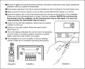
... COOL AUTO FAN RESET digits, press the reset button once again. If it does not snap properly, the thermostat may be damaged. s The installation is in AUTO. s Push excess wire back into hole to prevent interference with your house. RH RH RC RH G W Y FIGURE 3 FIGURE ...tighten the terminal screws securely, otherwise a loose wire could cause operational problems with mounting of the thermostat cover. s Insert the bottom tab on the main power. s Switch on the thermostat body into the wallplate. (NOTE: Do not force the thermostat onto the wallplate, as the terminal pins may ...
... COOL AUTO FAN RESET digits, press the reset button once again. If it does not snap properly, the thermostat may be damaged. s The installation is in AUTO. s Push excess wire back into hole to prevent interference with your house. RH RH RC RH G W Y FIGURE 3 FIGURE ...tighten the terminal screws securely, otherwise a loose wire could cause operational problems with mounting of the thermostat cover. s Insert the bottom tab on the main power. s Switch on the thermostat body into the wallplate. (NOTE: Do not force the thermostat onto the wallplate, as the terminal pins may ...


